EP4087718B1 - Luftfeder mit verbundteilen - Google Patents
Luftfeder mit verbundteilen Download PDFInfo
- Publication number
- EP4087718B1 EP4087718B1 EP21703336.4A EP21703336A EP4087718B1 EP 4087718 B1 EP4087718 B1 EP 4087718B1 EP 21703336 A EP21703336 A EP 21703336A EP 4087718 B1 EP4087718 B1 EP 4087718B1
- Authority
- EP
- European Patent Office
- Prior art keywords
- top plate
- clamp ring
- air spring
- flexible sleeve
- composite
- Prior art date
- Legal status (The legal status is an assumption and is not a legal conclusion. Google has not performed a legal analysis and makes no representation as to the accuracy of the status listed.)
- Active
Links
Images


Classifications
-
- B—PERFORMING OPERATIONS; TRANSPORTING
- B29—WORKING OF PLASTICS; WORKING OF SUBSTANCES IN A PLASTIC STATE IN GENERAL
- B29C—SHAPING OR JOINING OF PLASTICS; SHAPING OF MATERIAL IN A PLASTIC STATE, NOT OTHERWISE PROVIDED FOR; AFTER-TREATMENT OF THE SHAPED PRODUCTS, e.g. REPAIRING
- B29C45/00—Injection moulding, i.e. forcing the required volume of moulding material through a nozzle into a closed mould; Apparatus therefor
- B29C45/14—Injection moulding, i.e. forcing the required volume of moulding material through a nozzle into a closed mould; Apparatus therefor incorporating preformed parts or layers, e.g. injection moulding around inserts or for coating articles
-
- B—PERFORMING OPERATIONS; TRANSPORTING
- B60—VEHICLES IN GENERAL
- B60G—VEHICLE SUSPENSION ARRANGEMENTS
- B60G11/00—Resilient suspensions characterised by arrangement, location or kind of springs
- B60G11/26—Resilient suspensions characterised by arrangement, location or kind of springs having fluid springs only, e.g. hydropneumatic springs
- B60G11/27—Resilient suspensions characterised by arrangement, location or kind of springs having fluid springs only, e.g. hydropneumatic springs wherein the fluid is a gas
-
- F—MECHANICAL ENGINEERING; LIGHTING; HEATING; WEAPONS; BLASTING
- F16—ENGINEERING ELEMENTS AND UNITS; GENERAL MEASURES FOR PRODUCING AND MAINTAINING EFFECTIVE FUNCTIONING OF MACHINES OR INSTALLATIONS; THERMAL INSULATION IN GENERAL
- F16F—SPRINGS; SHOCK-ABSORBERS; MEANS FOR DAMPING VIBRATION
- F16F9/00—Springs, vibration-dampers, shock-absorbers, or similarly-constructed movement-dampers using a fluid or the equivalent as damping medium
- F16F9/02—Springs, vibration-dampers, shock-absorbers, or similarly-constructed movement-dampers using a fluid or the equivalent as damping medium using gas only or vacuum
- F16F9/04—Springs, vibration-dampers, shock-absorbers, or similarly-constructed movement-dampers using a fluid or the equivalent as damping medium using gas only or vacuum in a chamber with a flexible wall
- F16F9/0454—Springs, vibration-dampers, shock-absorbers, or similarly-constructed movement-dampers using a fluid or the equivalent as damping medium using gas only or vacuum in a chamber with a flexible wall characterised by the assembling method or by the mounting arrangement, e.g. mounting of the membrane
-
- F—MECHANICAL ENGINEERING; LIGHTING; HEATING; WEAPONS; BLASTING
- F16—ENGINEERING ELEMENTS AND UNITS; GENERAL MEASURES FOR PRODUCING AND MAINTAINING EFFECTIVE FUNCTIONING OF MACHINES OR INSTALLATIONS; THERMAL INSULATION IN GENERAL
- F16F—SPRINGS; SHOCK-ABSORBERS; MEANS FOR DAMPING VIBRATION
- F16F9/00—Springs, vibration-dampers, shock-absorbers, or similarly-constructed movement-dampers using a fluid or the equivalent as damping medium
- F16F9/02—Springs, vibration-dampers, shock-absorbers, or similarly-constructed movement-dampers using a fluid or the equivalent as damping medium using gas only or vacuum
- F16F9/04—Springs, vibration-dampers, shock-absorbers, or similarly-constructed movement-dampers using a fluid or the equivalent as damping medium using gas only or vacuum in a chamber with a flexible wall
- F16F9/05—Springs, vibration-dampers, shock-absorbers, or similarly-constructed movement-dampers using a fluid or the equivalent as damping medium using gas only or vacuum in a chamber with a flexible wall the flexible wall being of the rolling diaphragm type
-
- B—PERFORMING OPERATIONS; TRANSPORTING
- B60—VEHICLES IN GENERAL
- B60G—VEHICLE SUSPENSION ARRANGEMENTS
- B60G2202/00—Indexing codes relating to the type of spring, damper or actuator
- B60G2202/10—Type of spring
- B60G2202/15—Fluid spring
- B60G2202/152—Pneumatic spring
-
- B—PERFORMING OPERATIONS; TRANSPORTING
- B60—VEHICLES IN GENERAL
- B60G—VEHICLE SUSPENSION ARRANGEMENTS
- B60G2206/00—Indexing codes related to the manufacturing of suspensions: constructional features, the materials used, procedures or tools
- B60G2206/01—Constructional features of suspension elements, e.g. arms, dampers, springs
- B60G2206/40—Constructional features of dampers and/or springs
- B60G2206/42—Springs
- B60G2206/424—Plunger or top retainer construction for bellows or rolling lobe type air springs
-
- B—PERFORMING OPERATIONS; TRANSPORTING
- B60—VEHICLES IN GENERAL
- B60G—VEHICLE SUSPENSION ARRANGEMENTS
- B60G2206/00—Indexing codes related to the manufacturing of suspensions: constructional features, the materials used, procedures or tools
- B60G2206/01—Constructional features of suspension elements, e.g. arms, dampers, springs
- B60G2206/80—Manufacturing procedures
- B60G2206/81—Shaping
- B60G2206/8101—Shaping by casting
- B60G2206/81012—Shaping by casting by injection moulding
-
- F—MECHANICAL ENGINEERING; LIGHTING; HEATING; WEAPONS; BLASTING
- F16—ENGINEERING ELEMENTS AND UNITS; GENERAL MEASURES FOR PRODUCING AND MAINTAINING EFFECTIVE FUNCTIONING OF MACHINES OR INSTALLATIONS; THERMAL INSULATION IN GENERAL
- F16F—SPRINGS; SHOCK-ABSORBERS; MEANS FOR DAMPING VIBRATION
- F16F2222/00—Special physical effects, e.g. nature of damping effects
- F16F2222/12—Fluid damping
- F16F2222/126—Fluid damping using gases
-
- F—MECHANICAL ENGINEERING; LIGHTING; HEATING; WEAPONS; BLASTING
- F16—ENGINEERING ELEMENTS AND UNITS; GENERAL MEASURES FOR PRODUCING AND MAINTAINING EFFECTIVE FUNCTIONING OF MACHINES OR INSTALLATIONS; THERMAL INSULATION IN GENERAL
- F16F—SPRINGS; SHOCK-ABSORBERS; MEANS FOR DAMPING VIBRATION
- F16F2224/00—Materials; Material properties
- F16F2224/02—Materials; Material properties solids
- F16F2224/0241—Fibre-reinforced plastics [FRP]
-
- F—MECHANICAL ENGINEERING; LIGHTING; HEATING; WEAPONS; BLASTING
- F16—ENGINEERING ELEMENTS AND UNITS; GENERAL MEASURES FOR PRODUCING AND MAINTAINING EFFECTIVE FUNCTIONING OF MACHINES OR INSTALLATIONS; THERMAL INSULATION IN GENERAL
- F16F—SPRINGS; SHOCK-ABSORBERS; MEANS FOR DAMPING VIBRATION
- F16F2226/00—Manufacturing; Treatments
- F16F2226/04—Assembly or fixing methods; methods to form or fashion parts
-
- F—MECHANICAL ENGINEERING; LIGHTING; HEATING; WEAPONS; BLASTING
- F16—ENGINEERING ELEMENTS AND UNITS; GENERAL MEASURES FOR PRODUCING AND MAINTAINING EFFECTIVE FUNCTIONING OF MACHINES OR INSTALLATIONS; THERMAL INSULATION IN GENERAL
- F16F—SPRINGS; SHOCK-ABSORBERS; MEANS FOR DAMPING VIBRATION
- F16F2230/00—Purpose; Design features
- F16F2230/0005—Attachment, e.g. to facilitate mounting onto confer adjustability
-
- F—MECHANICAL ENGINEERING; LIGHTING; HEATING; WEAPONS; BLASTING
- F16—ENGINEERING ELEMENTS AND UNITS; GENERAL MEASURES FOR PRODUCING AND MAINTAINING EFFECTIVE FUNCTIONING OF MACHINES OR INSTALLATIONS; THERMAL INSULATION IN GENERAL
- F16F—SPRINGS; SHOCK-ABSORBERS; MEANS FOR DAMPING VIBRATION
- F16F2230/00—Purpose; Design features
- F16F2230/02—Surface features, e.g. notches or protuberances
Definitions
- An air spring may be used in a wide variety of vehicles and other machines.
- an air spring provides a cushioning between parts that move with respect to each other to reduce wear that may be caused by shock loads.
- An air spring may comprise a flexible member, such as an elastomeric sleeve that extends between a pair of plates, typically referred to as a top or bead plate and a bottom plate or piston.
- the elastomeric sleeve is attached to each of the top plate and the bottom plate to form an air tight seal. With the air tight seal, the elastomeric sleeve, top plate, and bottom plate form a pressurized chamber.
- the pressurized chamber contains a fluid, typically a gas such as air. The fluid contained in the pressurized chamber acts as a spring.
- the top plate, and the bottom plate are typically formed from a metal, such as, for example, iron or steel.
- a metal such as, for example, iron or steel.
- the iron or steel plates are exposed to the environment and suffer from corrosion, such as simple rusting or oxidation.
- the metal may be treated or coated, which for example zinc, so the steel is not exposed to the environment.
- the process of attaching the plates to the sleeve often compromises the treatment or coating, which leads to reduced effectiveness of the coating and, eventually, corrosion.
- EP 2 775 162 A2 discloses air spring comprising of a piston, a top plate, a clamp ring, and a flexible member which is affixed to the piston and the top plate.
- an air spring having at least one composite part will have a top plate, a flexible sleeve, and a clamp ring coupled together by an injection molded collar.
- the injection molded collar will be formed to hold the top plate, flexible sleeve, and clamp ring in compression to form an air tight seal.
- the top plate also is formed as a composite.
- the clamp ring also is formed as a composite.
- the top plate, clamp ring, and injection molded collar are all formed from composites.
- At least one of the clamp ring and top plate are formed with at least one of a plurality of indentations, perforations, channels, or a combination thereof.
- the indentations, perforations, channels, or combinations are filled with the injected plastic to facilitate the connection between the collar and the top plate and clamp ring.
- a method of forming an air spring having at least one composite part is provided.
- the top plate, clamp ring, and flexible sleeve for an air spring are placed into a mold of an injection mold press.
- the press applies a compressive force to the top plate, clamp ring, and flexible sleeve forming an air tight seal between the top plate, clamp ring, and flexible sleeve.
- Plastic is injected into the mold while the press is applying the compressive force, which compressive force is held until the injected plastic cures and forms the injected mold collar.
- the press is opened, and the air spring is removed.
- the parts can be subsequently machine finished.
- Figure 1 shows a cross-section of a conventional state of the art air spring 1.
- the conventional state of the art air spring 1 includes a steel bead plate 9, a flexible member 3, and a piston 4.
- the flexible member includes an upper portion of the flexible member 10 which extends from the upper end of the flexible member 12 to no more than 25% along the length of the flexible member 3 from the upper end of the flexible member 12 to the lower end of the flexible member 13.
- the upper portion of the flexible member 10 is adapted to be affixed to the steel bead plate 9 to create an air tight seal.
- the flexible member 3 also includes a lower portion of the flexible member 11 which extends from the lower end of the flexible member 13 to no more than 25% along the length of the flexible member 3 from the lower end of the flexible member 13 to the upper end of the flexible member 12.
- the lower portion of the flexible member 11 is adapted to be affixed to the piston 4 to create an air tight seal.
- the lower portion of the flexible member 11 may be secured in any conventional manner, including, but not limited to, crimping the lower portion of the flexible member 11 to the piston 4 or to a conventional lower retainer or by securing a lower bead core by a lower retainer.
- An internal bumper may be provided for absorbing impact forces.
- the steel bead plate 9, the flexible member 3, and the piston 4 define a pressurizable chamber 14.
- the pressurizable chamber 14 is generally filled with a gas, such as air or nitrogen, to a pressure greater than atmospheric pressure.
- the gas is usually air for economic reasons.
- the pressurizable chamber can optionally be filled with an inert gas, such as nitrogen to help protect the flexible member (a rubber component) from degradation caused by oxygen or ozone.
- the steel bead plate 9 is attached to either a fixed or movable component and the piston 4 is attached to a corresponding fixed or movable component so that loads tending to move the steel bead plate 9 and the piston 4 towards each other will be counteracted by the pressure within the pressurizable chamber 14.
- the steel bead plate 9 is rolled or crimped at the outer radial edge such that the upper portion 12 of the flexible member 3, i.e., the upper portion 12 that encompasses the retention bead (shown but not specifically referenced in figure 1 ).
- the steel bead plate 9 is subject to corrosion.
- the crimping (or rolling) of the steel bead plate 9 at the outer radial edge can cause cracks, sometime microcracks, that are further any potential corrosion or oxidation of the steel bead plate 9.
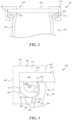
- FIG. 2 shows a cross-sectional view of a top 102 of an air spring 100 consistent with the technology of the present application.
- the bottom of the air spring 100 may be consistent with known technology for air spring's and is not shown herein expect as necessary for an understanding of the technology.
- the air spring 100 includes a top plate 202, a flexible sleeve 204, a clamp ring 214, and a collar 218.
- the top plate 202, the flexible sleeve 204, the clamp ring 214, and the collar 218 joint to form joint 200, which facilitates forming an air tight seal between the top plate 202 and the flexible sleeve 204 that allows the air spring to be pressurized, as shown in figure 2 .
- the joint 200 will be explained further below with reference to figure 3 .
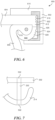
- Figure 3 shows a cross-sectional view of the joint 200 consistent with the technology of the present application.
- the joint 200 forms, among other things, an air tight seal 201 between the top plate 202 and the flexible sleeve 204.
- the terminal end 206 of the flexible sleeve 204 comprises a retention bead 208 that contains a wire member 210 to facilitate structural integrity.
- the wire member 210 may be optional in view of the improvements presented by the technology of the present application.
- the terminal end 206 of the flexible sleeve 204, or the retention bead 208, is captured in a cavity 212 formed by top plate 202 and a clamp ring 214.
- the top plate 202 does not need to be bent, but can remain a relatively flat, planar shape at the outer radial end portion 216.
- the clamp ring 214 is shown as having a crescent shape but could form other shapes.
- the cavity 212 is generally circular, oval, elliptical, or the like to facilitate capture of the retention bead, but the cavity 212 could be alterative geometric or random shapes that accommodate the retention bead 208.
- the annular clamp ring 214 has a seal end surface 213 that forms a gap G between a surface of the top plate 202 and the seal end surface 213.
- the flexible sleeve 204 extends from the retention bead through the gap G.
- the seal end surface 213 engages with the flexible sleeve 204 and the surface of the top plate 202 engages with the flexible sleeve 204 to form an air tight seal.
- the end 228 of the clamp ring engagement portion 226 is shown as squared off or with edges, but the end portion 228 may be rounded, blunt, or chamfered.
- the end portion 228 may, in certain embodiments, engage the flexible member 204 at times as the flexible member is pressurized and depressurized.
- the end portion 228 being rounded, blunt, or chamfered may reduce wear on the flexible member 204.
- the top plate 202, flexible sleeve 204, and clamp ring 214 are held in place and a press, such as an injection molding press, is applied to force the top plate 202 and clamp ring 214 together in compression such that the flexible sleeve 204 is compressed in the cavity 212.
- the flexible sleeve 204 is compressed in the gap G to form an air tight seal.
- the press compresses the parts, as explained, in a mold configured for injection molding.
- the mold forms the collar shape around the parts and a plastic is injected into the mold and held in place at pressure until the plastic cures such that the collar 218 is injection molded around the top plate 202 and clamp ring 214.
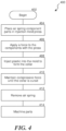
- FIG. 4 shows an exemplary method 400 of forming the air spring having composite parts consistent with the technology of the present application.
- the exemplary method 400 is illustrative and shown in several discrete steps. Each of the steps, in context, may be performed in alternative orders and/or simultaneously with other steps. Additionally, certain of the steps may be combined into a single step or any of the single steps may involve multiple additional or sub steps as required.
- the process begins at step 402.
- the component parts of the air spring including the top plate 202, the flexible sleeve 204, and the clamp ring 214, are arranged in a mold in an injection mold press, step 404. A force is applied to the component parts of the air spring by the injection mold press, step 406.
- the surface 404 of the top plate 202 may have indentations 500, perforations 502, or a combination thereof as well.
- the indentations 500, perforations 502, or the combination may increase the strength of the connection between the collar 218 and the top plate 202/clamp ring 214.
- a reinforcing rib 626 may be provided in the collar 602 (or the molded collar 218 above).
- the reinforcing rib 626 may be a metal or composite of additional strength to facilitate the structural integrity of the collar 602 as it is exposed to vibration, shock forces, corrosive environments, a combination thereof, or the like.
- the reinforcing rib 626 may be operatively shaped similar to the collar (as shown) or have alternative shapes including straight shapes.
- the top plate 202 and the clamp ring 214 form a junction 230.
- the junction 230 inhibits the injected plastic from contacting the retention bead 208 and flexible sleeve 204.
- the top plate 202 and clamp ring 214 may have perforations 502 that form through holes.
- the through holes 502 provide a pathway for the plastic of the injection molded collar to contact the flexible sleeve 204.
- the injected plastic flowing into the perforations may increase the strength of the connection, but may, in certain aspects, weaken or otherwise damage the flexible sleeve 204.
- column sleeves 232 may be provided providing a channel between the top plate 202 and the clamp ring 214 such that a barrier is provided between injection mold and the flexible sleeve. The injected plastic would thus flow from the collar lower part to the collar upper part through the clamp ring 214 and the top plate 202 forming a connector.
- the injection molded collar 218, 602 provides a strong connection between the top plate 202, 604 and the clamp ring 214, 608.
- the collar 281, 602 functions whether the top plate 202, 604 is a metal or a composite.
- the clamp ring 214, 608 may be a metal or composite.
- a stated range of 1 to 10 should be considered to include and provide support for claims that recite any and all subranges or individual values that are between and/or inclusive of the minimum value of 1 and the maximum value of 10; that is, all subranges beginning with a minimum value of 1 or more and ending with a maximum value of 10 or less (e.g., 5.5 to 10, 2.34 to 3.56, and so forth) or any values from 1 to 10 (e.g., 3, 5.8, 9.9994, and so forth).
Landscapes
- Engineering & Computer Science (AREA)
- General Engineering & Computer Science (AREA)
- Mechanical Engineering (AREA)
- Manufacturing & Machinery (AREA)
- Fluid-Damping Devices (AREA)
Claims (18)
- Luftfeder, umfassendeine obere Platte (202, 604) mit einer oberseitigen Fläche und einer unterseitigen Fläche, welche zur oberseitigen Fläche entgegengesetzt ist;einen nachgiebigen Blag (204) mit einem Haltekörper (208) an einem endständiger Abschnitt (206) des nachgiebigen Balgs (204);einen Klemmring (214), wobei der Klemmring (214) einen Hohlraum (212) mit der unterseitigen Fläche der oberen Platte (202) bildet, wobei der Haltekörper (208) sich in dem Hohlraum (212) befindet und der nachgiebige Balg (204) sich ausgehend von dem Haltekörper (208) durch den Spalt (G) erstreckt, welcher zwischen einer abdichtenden Endfläche (213) des Klemmrings (214) und der untenliegenden Fläche der oberen Platte (202) gebildet ist; undeine im Spritzgießverfahren hergestellte Einfassung (218), die aus einem spritzgegossenen Kunststoff gebildet ist, wobei die im Spritzgießverfahren hergestellte Einfassung (218) derart geformt ist, dass sie im Betrieb den Klemmring (214) an der oberen Platte (202) hält, sodass der Haltekörper (208) und der nachgiebige Balg (204) zusammengedrückt werden und eine luftundurchlässige Dichtung (201) zwischen der oberen Platte (202) und dem Haltekörper (208) sowie dem nachgiebigen Balg (204) bilden, wobei sich die im Spritzgießverfahren hergestellte Einfassung (218) von dem Klemmring (214) unterscheidet.
- Luftfeder nach Anspruch 1, wobei sie weiterhin einen Kolben (4) umfasst, welcher mit dem nachgiebigen Balg (204) gekoppelt ist.
- Luftfeder nach Anspruch 1, wobei die obere Platte (202) aus einem Verbundwerkstoff gebildet ist.
- Luftfeder nach Anspruch 1, wobei die obere Platte (202) aus einem Metall gebildet ist.
- Luftfeder nach Anspruch 1, wobei der Klemmring (214) aus einem Verbundwerkstoff gebildet ist.
- Luftfeder nach Anspruch 1, wobei der Klemmring (214) aus einem Metall gebildet ist.
- Luftfeder nach Anspruch 1, wobei die obere Platte (202) eine Mehrzahl an Einbuchtungen (500) und/oder Bohrungen (502) aufweist.
- Luftfeder nach Anspruch 1, wobei der Klemmring (214) eine Mehrzahl an Einbuchtungen (500) und/oder Bohrungen (502) aufweist.
- Luftfeder nach Anspruch 8, wobei die obere Platte (202) eine entsprechende Mehrzahl an Einbuchtungen (500) und/oder Bohrungen (502) aufweist.
- Luftfeder nach Anspruch 1, wobei die obere Platte (604) eine umlaufende Lippe (612) und eine radiale Kante aufweist.
- Luftfeder nach Anspruch 1, wobei die obere Platte (604) und/oder der Klemmring (608) mit Kanälen (622) und Graten (624) versehen sind, welche auf einer Außenfläche gebildet sind.
- Luftfeder nach Anspruch 1, wobei die im Spritzgießverfahren hergestellte Einfassung (602) mindestens ein Verstärkungsglied beinhaltet.
- Verfahren zur Bildung einer Luftfeder gemäß Anspruch 1, welche eine luftundurchlässige Dichtung zwischen einer oberen Platte (202) und einem nachgiebigen Balg (204) aufweist und mit Verbundwerkstoffteilen versehen ist, umfassend:Anordnen einer oberen Platte (202), eines nachgiebigen Balgs (204) mit einem Haltekörper (208) sowie eines Klemmrings (214) in einer Spritzgusspresse;Bewirken, dass die Spritzgusspresse die obere Platte (202) und den Klemmring (214) derart zusammendrückt, dass der nachgiebige Balg (204) und der Haltekörper (208) zusammengedrückt werden, um eine luftundurchlässige Dichtung (201) zu bilden;unter Aufrechterhaltung des Drucks, Einspritzen eines Kunststoffs in die Spritzgusspresse;Beibehalten des Drucks während der eingespritzte Kunststoff sich derart ausformt, dass er eine im Spritzgießverfahren hergestellte Einfassung (218) bildet, welche den Klemmring (214) und die obere Platte (202) derart koppelt, dass die obere Platte (202), nachgiebige Balg (204) und der Haltekörper (208) sowie der Klemmring (214) die luftundurchlässige Dichtung (201) bilden;Entspannen des Drucks, indem die Spritzgusspresse geöffnet wird; undEntnehmen der ausgeformten Luftfeder, die mindestens ein Verbundwerkstoffteil aufweist.
- Verfahren nach Anspruch 13, wobei die im Spritzgießverfahren hergestellte Einfassung (218) eine spanende Endbearbeitung erfährt.
- Verfahren nach Anspruch 13, wobei es weiterhin das Anordnen mindestens eines Verstärkungsglieds in der Spritzgusspresse umfasst, sodass das mindestens eine Verstärkungsglied in der im Spritzgießverfahren hergestellten Einfassung (218) enthalten ist.
- Verfahren nach Anspruch 13, wobei die obere Platte (202) und/oder der Klemmring (214) aus einem Verbundwerkstoff gebildet sind.
- Verfahren nach Anspruch 16, wobei sowohl die obere Platte (202) als auch der Klemmring (214) aus dem Verbundwerkstoff gebildet sind.
- Verfahren nach Anspruch 13, wobei das Beibehalten des Drucks, während sich der eingespritzte Kunststoff ausformt, ein Beibehalten des Drucks umfasst, während der eingespritzte Kunststoff erstarrt.
Applications Claiming Priority (2)
| Application Number | Priority Date | Filing Date | Title |
|---|---|---|---|
| US202062959531P | 2020-01-10 | 2020-01-10 | |
| PCT/US2021/012596 WO2021142190A1 (en) | 2020-01-10 | 2021-01-08 | Air spring having composite parts |
Publications (2)
| Publication Number | Publication Date |
|---|---|
| EP4087718A1 EP4087718A1 (de) | 2022-11-16 |
| EP4087718B1 true EP4087718B1 (de) | 2024-12-04 |
Family
ID=74550733
Family Applications (1)
| Application Number | Title | Priority Date | Filing Date |
|---|---|---|---|
| EP21703336.4A Active EP4087718B1 (de) | 2020-01-10 | 2021-01-08 | Luftfeder mit verbundteilen |
Country Status (3)
| Country | Link |
|---|---|
| US (1) | US12331805B2 (de) |
| EP (1) | EP4087718B1 (de) |
| WO (1) | WO2021142190A1 (de) |
Family Cites Families (8)
| Publication number | Priority date | Publication date | Assignee | Title |
|---|---|---|---|---|
| US4787606A (en) * | 1987-06-17 | 1988-11-29 | The Firestone Tire & Rubber Company | Beadless air spring |
| US4852861A (en) * | 1988-12-29 | 1989-08-01 | The Firestone Tire & Rubber Company | End cap assembly for air spring |
| DE10163818B4 (de) * | 2001-12-22 | 2020-08-20 | Contitech Luftfedersysteme Gmbh | Schlauchrollbalg-Feder |
| US6845973B2 (en) * | 2002-08-07 | 2005-01-25 | Bfs Diversified Products, Llc | Air spring with restraining cylinder |
| US7325794B2 (en) * | 2005-06-06 | 2008-02-05 | Bfs Diversified Products, Llc | Air spring assembly and method |
| EP2775162B1 (de) * | 2013-03-08 | 2019-10-30 | ContiTech USA, Inc. | Verbundstoffwulstplatte und Luftfeder damit |
| EP3263372A1 (de) * | 2016-04-21 | 2018-01-03 | Firestone Industrial Products Company, LLC | Gasfederendelemente sowie gasfederanordnungen, federungssysteme und verfahren |
| DE102017202094A1 (de) * | 2017-02-09 | 2018-08-09 | Contitech Luftfedersysteme Gmbh | Luftfeder mit einem Kunststoffdeckel |
-
2021
- 2021-01-08 EP EP21703336.4A patent/EP4087718B1/de active Active
- 2021-01-08 US US17/790,682 patent/US12331805B2/en active Active
- 2021-01-08 WO PCT/US2021/012596 patent/WO2021142190A1/en not_active Ceased
Also Published As
| Publication number | Publication date |
|---|---|
| EP4087718A1 (de) | 2022-11-16 |
| US20230042131A1 (en) | 2023-02-09 |
| WO2021142190A1 (en) | 2021-07-15 |
| US12331805B2 (en) | 2025-06-17 |
Similar Documents
| Publication | Publication Date | Title |
|---|---|---|
| CA2990729C (en) | Bar pin bushing for vehicle suspension and corresponding mounting method | |
| EP0306732B1 (de) | Luftfeder mit innenliegendem Dichtungsband und Verfahren zu dessen Einbau | |
| US10767721B2 (en) | Bar pin bushing for vehicle suspension | |
| EP0378748B1 (de) | Deckelbefestigung für eine Luftfeder | |
| EP0379667B1 (de) | Befestigungsring für eine pneumatische Feder | |
| EP2775162B1 (de) | Verbundstoffwulstplatte und Luftfeder damit | |
| US20060208406A2 (en) | Spring seat assembly | |
| US6652150B2 (en) | Bearing arrangement and method for fixing at least one bearing in place in a bearing retainer | |
| US20030102194A1 (en) | Suspension support | |
| EP1279855A3 (de) | Schwingungsdämpfende Buchse und Verfahren zur Herstellung derselben | |
| US10035526B2 (en) | Brake piston assembly | |
| US12331805B2 (en) | Air spring having composite parts | |
| EP0939241B1 (de) | Eine tränenförmige Klemmvorrichtung und konische Endkappe für eine Luftfeder | |
| US4793598A (en) | Air spring having internal sealing band and method of installing same | |
| JPS6392845A (ja) | 内部密封帯を有する空気バネ及び空気バネ組立方法 | |
| CN102196953A (zh) | 用于在处于汽车中的组装件的两个构件之间形成形锁合连接的方法、工具以及组装件 | |
| AU2019206508B2 (en) | Bar pin bushing for vehicle suspension | |
| US6106157A (en) | Tension roll | |
| KR101657998B1 (ko) | 피스톤씰의 접착력 보강을 위한 제조 공법 | |
| US20170370439A1 (en) | Counterfeit refrigerant analyzer | |
| JPH08183117A (ja) | ブラケット一体型防振装置の製造方法 | |
| AU4527397A (en) | A universal and adaptable hose fixture method | |
| AU2014412853A1 (en) | Improved brake piston assembly | |
| DE102016205627A1 (de) | Kolben und Kolbenvorrichtung |
Legal Events
| Date | Code | Title | Description |
|---|---|---|---|
| STAA | Information on the status of an ep patent application or granted ep patent |
Free format text: STATUS: UNKNOWN |
|
| STAA | Information on the status of an ep patent application or granted ep patent |
Free format text: STATUS: THE INTERNATIONAL PUBLICATION HAS BEEN MADE |
|
| PUAI | Public reference made under article 153(3) epc to a published international application that has entered the european phase |
Free format text: ORIGINAL CODE: 0009012 |
|
| STAA | Information on the status of an ep patent application or granted ep patent |
Free format text: STATUS: REQUEST FOR EXAMINATION WAS MADE |
|
| 17P | Request for examination filed |
Effective date: 20220617 |
|
| AK | Designated contracting states |
Kind code of ref document: A1 Designated state(s): AL AT BE BG CH CY CZ DE DK EE ES FI FR GB GR HR HU IE IS IT LI LT LU LV MC MK MT NL NO PL PT RO RS SE SI SK SM TR |
|
| DAV | Request for validation of the european patent (deleted) | ||
| DAX | Request for extension of the european patent (deleted) | ||
| GRAP | Despatch of communication of intention to grant a patent |
Free format text: ORIGINAL CODE: EPIDOSNIGR1 |
|
| STAA | Information on the status of an ep patent application or granted ep patent |
Free format text: STATUS: GRANT OF PATENT IS INTENDED |
|
| INTG | Intention to grant announced |
Effective date: 20240625 |
|
| GRAS | Grant fee paid |
Free format text: ORIGINAL CODE: EPIDOSNIGR3 |
|
| GRAA | (expected) grant |
Free format text: ORIGINAL CODE: 0009210 |
|
| STAA | Information on the status of an ep patent application or granted ep patent |
Free format text: STATUS: THE PATENT HAS BEEN GRANTED |
|
| P01 | Opt-out of the competence of the unified patent court (upc) registered |
Free format text: CASE NUMBER: APP_56240/2024 Effective date: 20241015 |
|
| AK | Designated contracting states |
Kind code of ref document: B1 Designated state(s): AL AT BE BG CH CY CZ DE DK EE ES FI FR GB GR HR HU IE IS IT LI LT LU LV MC MK MT NL NO PL PT RO RS SE SI SK SM TR |
|
| REG | Reference to a national code |
Ref country code: CH Ref legal event code: EP |
|
| REG | Reference to a national code |
Ref country code: DE Ref legal event code: R096 Ref document number: 602021022817 Country of ref document: DE |
|
| REG | Reference to a national code |
Ref country code: IE Ref legal event code: FG4D |
|
| REG | Reference to a national code |
Ref country code: LT Ref legal event code: MG9D |
|
| REG | Reference to a national code |
Ref country code: NL Ref legal event code: MP Effective date: 20241204 |
|
| PG25 | Lapsed in a contracting state [announced via postgrant information from national office to epo] |
Ref country code: HR Free format text: LAPSE BECAUSE OF FAILURE TO SUBMIT A TRANSLATION OF THE DESCRIPTION OR TO PAY THE FEE WITHIN THE PRESCRIBED TIME-LIMIT Effective date: 20241204 |
|
| PG25 | Lapsed in a contracting state [announced via postgrant information from national office to epo] |
Ref country code: FI Free format text: LAPSE BECAUSE OF FAILURE TO SUBMIT A TRANSLATION OF THE DESCRIPTION OR TO PAY THE FEE WITHIN THE PRESCRIBED TIME-LIMIT Effective date: 20241204 |
|
| PG25 | Lapsed in a contracting state [announced via postgrant information from national office to epo] |
Ref country code: BG Free format text: LAPSE BECAUSE OF FAILURE TO SUBMIT A TRANSLATION OF THE DESCRIPTION OR TO PAY THE FEE WITHIN THE PRESCRIBED TIME-LIMIT Effective date: 20241204 |
|
| PG25 | Lapsed in a contracting state [announced via postgrant information from national office to epo] |
Ref country code: ES Free format text: LAPSE BECAUSE OF FAILURE TO SUBMIT A TRANSLATION OF THE DESCRIPTION OR TO PAY THE FEE WITHIN THE PRESCRIBED TIME-LIMIT Effective date: 20241204 |
|
| PG25 | Lapsed in a contracting state [announced via postgrant information from national office to epo] |
Ref country code: NO Free format text: LAPSE BECAUSE OF FAILURE TO SUBMIT A TRANSLATION OF THE DESCRIPTION OR TO PAY THE FEE WITHIN THE PRESCRIBED TIME-LIMIT Effective date: 20250304 |
|
| PG25 | Lapsed in a contracting state [announced via postgrant information from national office to epo] |
Ref country code: LV Free format text: LAPSE BECAUSE OF FAILURE TO SUBMIT A TRANSLATION OF THE DESCRIPTION OR TO PAY THE FEE WITHIN THE PRESCRIBED TIME-LIMIT Effective date: 20241204 Ref country code: GR Free format text: LAPSE BECAUSE OF FAILURE TO SUBMIT A TRANSLATION OF THE DESCRIPTION OR TO PAY THE FEE WITHIN THE PRESCRIBED TIME-LIMIT Effective date: 20250305 |
|
| PG25 | Lapsed in a contracting state [announced via postgrant information from national office to epo] |
Ref country code: RS Free format text: LAPSE BECAUSE OF FAILURE TO SUBMIT A TRANSLATION OF THE DESCRIPTION OR TO PAY THE FEE WITHIN THE PRESCRIBED TIME-LIMIT Effective date: 20250304 |
|
| PG25 | Lapsed in a contracting state [announced via postgrant information from national office to epo] |
Ref country code: NL Free format text: LAPSE BECAUSE OF FAILURE TO SUBMIT A TRANSLATION OF THE DESCRIPTION OR TO PAY THE FEE WITHIN THE PRESCRIBED TIME-LIMIT Effective date: 20241204 |
|
| REG | Reference to a national code |
Ref country code: AT Ref legal event code: MK05 Ref document number: 1747696 Country of ref document: AT Kind code of ref document: T Effective date: 20241204 |
|
| PG25 | Lapsed in a contracting state [announced via postgrant information from national office to epo] |
Ref country code: SM Free format text: LAPSE BECAUSE OF FAILURE TO SUBMIT A TRANSLATION OF THE DESCRIPTION OR TO PAY THE FEE WITHIN THE PRESCRIBED TIME-LIMIT Effective date: 20241204 |
|
| PG25 | Lapsed in a contracting state [announced via postgrant information from national office to epo] |
Ref country code: PL Free format text: LAPSE BECAUSE OF FAILURE TO SUBMIT A TRANSLATION OF THE DESCRIPTION OR TO PAY THE FEE WITHIN THE PRESCRIBED TIME-LIMIT Effective date: 20241204 |
|
| PG25 | Lapsed in a contracting state [announced via postgrant information from national office to epo] |
Ref country code: IS Free format text: LAPSE BECAUSE OF FAILURE TO SUBMIT A TRANSLATION OF THE DESCRIPTION OR TO PAY THE FEE WITHIN THE PRESCRIBED TIME-LIMIT Effective date: 20250404 |
|
| PG25 | Lapsed in a contracting state [announced via postgrant information from national office to epo] |
Ref country code: PT Free format text: LAPSE BECAUSE OF FAILURE TO SUBMIT A TRANSLATION OF THE DESCRIPTION OR TO PAY THE FEE WITHIN THE PRESCRIBED TIME-LIMIT Effective date: 20250404 |
|
| PG25 | Lapsed in a contracting state [announced via postgrant information from national office to epo] |
Ref country code: EE Free format text: LAPSE BECAUSE OF FAILURE TO SUBMIT A TRANSLATION OF THE DESCRIPTION OR TO PAY THE FEE WITHIN THE PRESCRIBED TIME-LIMIT Effective date: 20241204 |
|
| PG25 | Lapsed in a contracting state [announced via postgrant information from national office to epo] |
Ref country code: RO Free format text: LAPSE BECAUSE OF FAILURE TO SUBMIT A TRANSLATION OF THE DESCRIPTION OR TO PAY THE FEE WITHIN THE PRESCRIBED TIME-LIMIT Effective date: 20241204 Ref country code: AT Free format text: LAPSE BECAUSE OF FAILURE TO SUBMIT A TRANSLATION OF THE DESCRIPTION OR TO PAY THE FEE WITHIN THE PRESCRIBED TIME-LIMIT Effective date: 20241204 |
|
| PG25 | Lapsed in a contracting state [announced via postgrant information from national office to epo] |
Ref country code: SK Free format text: LAPSE BECAUSE OF FAILURE TO SUBMIT A TRANSLATION OF THE DESCRIPTION OR TO PAY THE FEE WITHIN THE PRESCRIBED TIME-LIMIT Effective date: 20241204 |
|
| PG25 | Lapsed in a contracting state [announced via postgrant information from national office to epo] |
Ref country code: CZ Free format text: LAPSE BECAUSE OF FAILURE TO SUBMIT A TRANSLATION OF THE DESCRIPTION OR TO PAY THE FEE WITHIN THE PRESCRIBED TIME-LIMIT Effective date: 20241204 |
|
| PG25 | Lapsed in a contracting state [announced via postgrant information from national office to epo] |
Ref country code: IT Free format text: LAPSE BECAUSE OF FAILURE TO SUBMIT A TRANSLATION OF THE DESCRIPTION OR TO PAY THE FEE WITHIN THE PRESCRIBED TIME-LIMIT Effective date: 20241204 |
|
| REG | Reference to a national code |
Ref country code: CH Ref legal event code: PL |
|
| REG | Reference to a national code |
Ref country code: DE Ref legal event code: R097 Ref document number: 602021022817 Country of ref document: DE |
|
| PG25 | Lapsed in a contracting state [announced via postgrant information from national office to epo] |
Ref country code: SE Free format text: LAPSE BECAUSE OF FAILURE TO SUBMIT A TRANSLATION OF THE DESCRIPTION OR TO PAY THE FEE WITHIN THE PRESCRIBED TIME-LIMIT Effective date: 20241204 |
|
| PG25 | Lapsed in a contracting state [announced via postgrant information from national office to epo] |
Ref country code: LU Free format text: LAPSE BECAUSE OF NON-PAYMENT OF DUE FEES Effective date: 20250108 Ref country code: MC Free format text: LAPSE BECAUSE OF FAILURE TO SUBMIT A TRANSLATION OF THE DESCRIPTION OR TO PAY THE FEE WITHIN THE PRESCRIBED TIME-LIMIT Effective date: 20241204 |
|
| PG25 | Lapsed in a contracting state [announced via postgrant information from national office to epo] |
Ref country code: DK Free format text: LAPSE BECAUSE OF FAILURE TO SUBMIT A TRANSLATION OF THE DESCRIPTION OR TO PAY THE FEE WITHIN THE PRESCRIBED TIME-LIMIT Effective date: 20241204 |
|
| PLBE | No opposition filed within time limit |
Free format text: ORIGINAL CODE: 0009261 |
|
| STAA | Information on the status of an ep patent application or granted ep patent |
Free format text: STATUS: NO OPPOSITION FILED WITHIN TIME LIMIT |
|
| PG25 | Lapsed in a contracting state [announced via postgrant information from national office to epo] |
Ref country code: BE Free format text: LAPSE BECAUSE OF NON-PAYMENT OF DUE FEES Effective date: 20250131 |
|
| PG25 | Lapsed in a contracting state [announced via postgrant information from national office to epo] |
Ref country code: CH Free format text: LAPSE BECAUSE OF NON-PAYMENT OF DUE FEES Effective date: 20250131 |
|
| REG | Reference to a national code |
Ref country code: BE Ref legal event code: MM Effective date: 20250131 |
|
| 26N | No opposition filed |
Effective date: 20250905 |
|
| GBPC | Gb: european patent ceased through non-payment of renewal fee |
Effective date: 20250304 |
|
| PG25 | Lapsed in a contracting state [announced via postgrant information from national office to epo] |
Ref country code: GB Free format text: LAPSE BECAUSE OF NON-PAYMENT OF DUE FEES Effective date: 20250304 |
|
| PG25 | Lapsed in a contracting state [announced via postgrant information from national office to epo] |
Ref country code: IE Free format text: LAPSE BECAUSE OF NON-PAYMENT OF DUE FEES Effective date: 20250108 |
|
| PGFP | Annual fee paid to national office [announced via postgrant information from national office to epo] |
Ref country code: DE Payment date: 20260127 Year of fee payment: 6 |
|
| PGFP | Annual fee paid to national office [announced via postgrant information from national office to epo] |
Ref country code: FR Payment date: 20260126 Year of fee payment: 6 |
|
| PG25 | Lapsed in a contracting state [announced via postgrant information from national office to epo] |
Ref country code: CY Free format text: LAPSE BECAUSE OF FAILURE TO SUBMIT A TRANSLATION OF THE DESCRIPTION OR TO PAY THE FEE WITHIN THE PRESCRIBED TIME-LIMIT Effective date: 20241204 |
|
| PG25 | Lapsed in a contracting state [announced via postgrant information from national office to epo] |
Ref country code: TR Free format text: LAPSE BECAUSE OF FAILURE TO SUBMIT A TRANSLATION OF THE DESCRIPTION OR TO PAY THE FEE WITHIN THE PRESCRIBED TIME-LIMIT Effective date: 20241204 |
|
| PG25 | Lapsed in a contracting state [announced via postgrant information from national office to epo] |
Ref country code: LT Free format text: LAPSE BECAUSE OF FAILURE TO SUBMIT A TRANSLATION OF THE DESCRIPTION OR TO PAY THE FEE WITHIN THE PRESCRIBED TIME-LIMIT Effective date: 20241204 |