EP4088042B1 - Amortisseur de vibrations torsionnelles équipé d'un limiteur de couple comportant des rivets goujons et des garnitures de friction humides,ainsi que le procédé d'installation correspondant - Google Patents
Amortisseur de vibrations torsionnelles équipé d'un limiteur de couple comportant des rivets goujons et des garnitures de friction humides,ainsi que le procédé d'installation correspondant Download PDFInfo
- Publication number
- EP4088042B1 EP4088042B1 EP20816892.2A EP20816892A EP4088042B1 EP 4088042 B1 EP4088042 B1 EP 4088042B1 EP 20816892 A EP20816892 A EP 20816892A EP 4088042 B1 EP4088042 B1 EP 4088042B1
- Authority
- EP
- European Patent Office
- Prior art keywords
- torsional vibration
- vibration damper
- disc
- output hub
- spring
- Prior art date
- Legal status (The legal status is an assumption and is not a legal conclusion. Google has not performed a legal analysis and makes no representation as to the accuracy of the status listed.)
- Active
Links
Images


Classifications
-
- F—MECHANICAL ENGINEERING; LIGHTING; HEATING; WEAPONS; BLASTING
- F16—ENGINEERING ELEMENTS AND UNITS; GENERAL MEASURES FOR PRODUCING AND MAINTAINING EFFECTIVE FUNCTIONING OF MACHINES OR INSTALLATIONS; THERMAL INSULATION IN GENERAL
- F16F—SPRINGS; SHOCK-ABSORBERS; MEANS FOR DAMPING VIBRATION
- F16F15/00—Suppression of vibrations in systems; Means or arrangements for avoiding or reducing out-of-balance forces, e.g. due to motion
- F16F15/10—Suppression of vibrations in rotating systems by making use of members moving with the system
- F16F15/12—Suppression of vibrations in rotating systems by making use of members moving with the system using elastic members or friction-damping members, e.g. between a rotating shaft and a gyratory mass mounted thereon
- F16F15/131—Suppression of vibrations in rotating systems by making use of members moving with the system using elastic members or friction-damping members, e.g. between a rotating shaft and a gyratory mass mounted thereon the rotating system comprising two or more gyratory masses
- F16F15/13142—Suppression of vibrations in rotating systems by making use of members moving with the system using elastic members or friction-damping members, e.g. between a rotating shaft and a gyratory mass mounted thereon the rotating system comprising two or more gyratory masses characterised by the method of assembly, production or treatment
- F16F15/1315—Multi-part primary or secondary masses, e.g. assembled from pieces of sheet steel
-
- F—MECHANICAL ENGINEERING; LIGHTING; HEATING; WEAPONS; BLASTING
- F16—ENGINEERING ELEMENTS AND UNITS; GENERAL MEASURES FOR PRODUCING AND MAINTAINING EFFECTIVE FUNCTIONING OF MACHINES OR INSTALLATIONS; THERMAL INSULATION IN GENERAL
- F16F—SPRINGS; SHOCK-ABSORBERS; MEANS FOR DAMPING VIBRATION
- F16F15/00—Suppression of vibrations in systems; Means or arrangements for avoiding or reducing out-of-balance forces, e.g. due to motion
- F16F15/10—Suppression of vibrations in rotating systems by making use of members moving with the system
- F16F15/12—Suppression of vibrations in rotating systems by making use of members moving with the system using elastic members or friction-damping members, e.g. between a rotating shaft and a gyratory mass mounted thereon
- F16F15/131—Suppression of vibrations in rotating systems by making use of members moving with the system using elastic members or friction-damping members, e.g. between a rotating shaft and a gyratory mass mounted thereon the rotating system comprising two or more gyratory masses
- F16F15/133—Suppression of vibrations in rotating systems by making use of members moving with the system using elastic members or friction-damping members, e.g. between a rotating shaft and a gyratory mass mounted thereon the rotating system comprising two or more gyratory masses using springs as elastic members, e.g. metallic springs
- F16F15/134—Wound springs
-
- F—MECHANICAL ENGINEERING; LIGHTING; HEATING; WEAPONS; BLASTING
- F16—ENGINEERING ELEMENTS AND UNITS; GENERAL MEASURES FOR PRODUCING AND MAINTAINING EFFECTIVE FUNCTIONING OF MACHINES OR INSTALLATIONS; THERMAL INSULATION IN GENERAL
- F16F—SPRINGS; SHOCK-ABSORBERS; MEANS FOR DAMPING VIBRATION
- F16F15/00—Suppression of vibrations in systems; Means or arrangements for avoiding or reducing out-of-balance forces, e.g. due to motion
- F16F15/10—Suppression of vibrations in rotating systems by making use of members moving with the system
- F16F15/12—Suppression of vibrations in rotating systems by making use of members moving with the system using elastic members or friction-damping members, e.g. between a rotating shaft and a gyratory mass mounted thereon
- F16F15/131—Suppression of vibrations in rotating systems by making use of members moving with the system using elastic members or friction-damping members, e.g. between a rotating shaft and a gyratory mass mounted thereon the rotating system comprising two or more gyratory masses
- F16F15/139—Suppression of vibrations in rotating systems by making use of members moving with the system using elastic members or friction-damping members, e.g. between a rotating shaft and a gyratory mass mounted thereon the rotating system comprising two or more gyratory masses characterised by friction-damping means
-
- F—MECHANICAL ENGINEERING; LIGHTING; HEATING; WEAPONS; BLASTING
- F16—ENGINEERING ELEMENTS AND UNITS; GENERAL MEASURES FOR PRODUCING AND MAINTAINING EFFECTIVE FUNCTIONING OF MACHINES OR INSTALLATIONS; THERMAL INSULATION IN GENERAL
- F16F—SPRINGS; SHOCK-ABSORBERS; MEANS FOR DAMPING VIBRATION
- F16F2230/00—Purpose; Design features
- F16F2230/46—Maintenance
Definitions
- the invention relates to a torsional vibration damper of an internal combustion engine-driven motor vehicle, which is constructed as a dual-mass flywheel and comprises a primary part fastened to a crankshaft and a secondary part assigned to an output side, which are arranged so as to be rotatable together about an axis of rotation and rotatable relative to one another and between which a spring damper device is arranged in the torque flow, wherein the multi-part secondary part includes a torque limiter, the carrier flange of which is indirectly coupled to an output hub via at least one friction lining and a guide disk.
- Torsional vibration dampers designed as dual-mass flywheels, are used to dampen torsional vibrations in the drive train of motor vehicles.
- the trigger for torsional vibrations is the periodic combustion cycle of the reciprocating piston internal combustion engine, which in combination with the ignition sequence leads to rotational irregularities that are introduced into the drive train by the crankshaft.
- torsional vibration dampers constructed as dual-mass flywheels (DMF) are known from the state of the art.
- DMF dual-mass flywheels
- the DE 10 2012 202 255 A1 a torsional vibration damper of this type that can be used for damping or damping in drive trains between the crankshaft of the internal combustion engine and, for example, a shift separating clutch upstream of the manual transmission.
- torsional vibration dampers are often supplemented by a torque limiter (DMB), which protects downstream components of the drive train, such as a gearbox, from occurring torque peaks or limits the transmittable torque of the torsional vibration damper.
- DMB torque limiter
- Such a torsional vibration damper is in the DE 10 2017 119 375 A1 This comprises a primary part which is arranged to be rotatable about an axis of rotation and a secondary part which is arranged to be rotatable to a limited extent relative to the primary part, counter to the effect of a spring damper device housed in an annular chamber of the primary part.
- a torque limiter is integrated in an annular chamber together with the spring damper device between an output hub of the secondary part and the spring damper device.
- a typical design of the torsional vibration damper provides for the primary part to be screwed on the drive side, with the fastening screws being inserted through openings in the secondary part as well as through holes in the primary part of the torsional vibration damper. During initial assembly, the openings are aligned with the holes so that the fastening screws can be inserted without hindrance. If the torque limiter, which acts as a slip clutch, is activated or triggered during operation due to a set maximum torque being exceeded, a component of the secondary part rotates relative to the primary part of the torsional vibration damper. This results in an offset between the openings and the holes, which means that dismantling the torsional vibration damper is not possible or requires a great deal of assembly effort due to a lack of alignment.
- the document DE 10 2016 204261 A1 discloses a torsional vibration damper according to the preamble of claim 1.
- the structure according to the invention provides that the output hub is supported in an axially centered manner directly or indirectly on a friction ring connected to the primary part via a carrier ring and is positively connected via a toothing to a toothed sheet metal disk in front of the guide disk, wherein an axial displacement of the output hub against a spring force of at least one disc spring releases the toothing and interrupts a torque transmission of the torsional vibration damper and the output hub can then be rotated until the position of openings in the output hub coincides with bores in the primary part, which are intended to accommodate screws for fastening the torsional vibration damper.
- the design enables the gearing to be released by pulling or axially shifting the output hub against a compressive force of the disc spring, the tooth profile of which, in the operating state, engages positively in a counter-gearing of the sheet metal disk in the torque-transmitting position.
- the output hub In a position axially distant from the sheet metal disk and offset from the gearing, the output hub can be rotated relative to the sheet metal disk.
- the output hub can be rotated until a matching position or an identical hole pattern is established between the openings in the output hub and the holes in the primary part or the fastening screws inserted therein, with which the torsional vibration damper can be screwed to the crankshaft.
- the output hub moves automatically due to the spring force of the disc spring to the starting position in which the output hub is toothed with the sheet metal disk in a torque-transmitting position.
- the twisted, changed position of the output hub allows unhindered access to the fastening screws through the openings in the output hub, which simplifies disassembly and reassembly of the torsional vibration damper.
- the invention advantageously makes disassembly of the torsional vibration damper significantly easier and at the same time enables reassembly.
- a relative rotation of the output hub with respect to the fastening screws due to a triggered or activated torque limiter required a high level of assembly effort or the use of special tools in order to bring the output hub back into a position that allows unhindered access to the fastening screws.
- the concept according to the invention can be used to align the position of the output hub with the fastening screws using a simple measure that does not require any special tools. Due to the simplified disassembly, a decisive cost advantage can be achieved with the invention.
- the torque limiter forms a U-shaped receptacle that is axially limited by means of cranked sections of the guide disk and a support disk, open radially in the direction of the spring damper device, and intended for the support flange and for friction linings.
- the receptacle formed by the interconnected, preferably riveted components creates a protected position for the friction linings, which has a positive effect on the service life of the torque limiter.
- the torque limiter includes a carrier flange to which a disk-like, greased or oiled friction lining is fixed on both sides.
- the friction linings are guided with force on the contact surfaces of the guide disk and the support disk. Due to the torque limiter's mount being open in the direction of the spring damper device, the friction linings are lubricated by the lubricant of the spring damper device, also known as arc spring grease, when the torsional vibration damper is in operation.
- the installation position and the lubrication of the friction linings make it possible to achieve an advantageously low-variance friction coefficient of the torque limiter over the service life of the torsional vibration damper.
- an annular space delimited, for example, by the components of the primary part and the secondary part can be filled with lubricant. to form a lubricant reservoir, which also lubricates the friction linings.
- a preferred further embodiment of the invention provides that a disc spring membrane is inserted between the guide disk and the toothed sheet metal disk, which is supported radially on the outside via a friction ring on the inside on a primary cover of the primary part. Furthermore, the disc spring membrane forms a radially inner section that covers the front of the friction ring and on which the output hub is axially supported in a centered manner.
- the membrane also known as the disc spring sealing membrane, serves to seal the spring chamber of the spring damper device and at the same time the torque limiter and effectively prevents the ingress of dirt or water.
- the disc spring membrane exerts an axial force on the sheet metal disk and thus on the torque limiter.
- An advantageous embodiment of the invention comprises rivet connections, via which essential components of the secondary part are joined together to form a structural unit.
- rivets are provided symmetrically distributed around the circumference, with which the support disk, the guide disk, the disc spring membrane, the sheet metal disk and the output hub are connected.
- At least one rivet is designed as a stepped rivet, on the rivet head of which the disc spring is supported, which mutually apply force to the output hub.
- three or more stepped rivets are provided to achieve uniform support of the disc spring.
- a friction ring positioned radially in the direction of the axis of rotation of the torsional vibration damper can be included.
- the friction ring which is operatively connected to the output hub
- a carrier ring which is screwed to the crankshaft together with the primary part via the fastening screws.
- the centering and/or axial support of the output hub is therefore placed radially below the fastening screws.
- the associated friction ring is preferably materially bonded, for example by means of Gluing or vulcanizing fixes the parts in position. Alternatively or in addition to this, a form-fitting fastening is possible.
- the torsional vibration damper according to the invention which can be easily dismantled and assembled and is equipped with a torque limiter and, if required, a pre-damper, is preferably suitable for hybrid applications.
- a torsional vibration damper also referred to as a hybrid module, is integrated into a drive train of a motor vehicle that is alternatively powered by an internal combustion engine or an electric motor or is powered by both drive sources simultaneously.
- the invention meets the requirement of motor vehicle manufacturers to equip torsional vibration dampers intended for DHT hybrid applications (dedictated hybrid transmission) with torque limiters in order to protect components within the transmission from overload in particular.
- the components of the secondary part such as the support flange, support disk, guide disk, sheet metal disk and output hub, as a formed part or stamped part.
- these processes can also be used to manufacture the components of the primary part in a weight-optimized manner and with sufficient component rigidity without cutting at low cost, which can also achieve a weight advantage compared to similarly designed cast parts.
- a further aspect of the invention relates to a method with which the torsional vibration damper on the crankshaft of an internal combustion engine can be dismantled.
- a first method step provides for the interruption of a toothing between two components of the secondary part by means of an axial displacement. To do this, the output hub is first displaced relative to a sheet metal disk by pulling a disc spring force directed against a spring force.
- the output hub is rotated to a position in which the position between openings or recesses in the output hub and the fastening screws of the torsional vibration damper is aligned. Without an applied axial force, the output hub automatically moves in the direction of the sheet metal disk. whereby these components are again connected in a rotationally fixed manner via the gearing. In this position, the fastening screws can be loosened using a normal tool guided through the recesses in the output hub.
- This output hub position also enables the torsional vibration damper to be reassembled.
- the Fig. 1 shows a first embodiment of a torsional vibration damper 1 according to the invention, constructed as a dual-mass flywheel, consisting of a primary part 2 and a secondary part 3, which can be rotated together about the axis of rotation 4 and can be rotated to a limited extent relative to one another. Between the primary part 2 and the secondary part 3, a spring damper device 5 with mechanical energy storage devices designed as arc springs 6 is effective.
- the torsional vibration damper 1 intended for a drive train of an internal combustion engine-driven motor vehicle, in particular for a DHT hybrid application, has the task of damping rotational irregularities in the drive train triggered by the internal combustion engine.
- the primary part 2 comprises a flange element 7, which is connected radially on the outside in one piece to a primary cover 8, which together enclose a spring chamber 9 intended to accommodate the arc springs 6.
- the arc springs 6 are supported with one spring end on stops (not shown) of the primary part 2 and with the other spring end on a support flange 10 of the multi-part secondary part 3.
- the primary part 2 of the torsional vibration damper 1 is fastened to a crankshaft (not shown) of an internal combustion engine by means of a large number of screws, which are inserted into associated holes 11 of the flange element 7 of the primary part 2.
- the secondary part 3 is connected to a transmission input shaft (not shown) in a form-fitting manner via an output hub 12, preferably with a toothed profile.
- a torque limiter 13 designed as a friction device is integrated in the torsional vibration damper 1, which is intended to limit components downstream of the torsional vibration damper 1 in particular to a torque that can be transmitted reliably.
- the torque limiter 13 is formed from the carrier flange 10, which is inserted radially on the inside into an open, U-shaped receptacle aligned with the spring damper device 5. 14, which is axially limited by oppositely cranked sections of a guide disk 15 and a support disk 16. The carrier flange 10 is guided on both sides by a disk-like, oiled friction lining 24, 25 on the guide disk 15 and the support disk 16. Due to the spring chamber 9, which is radially open at the bottom and at least partially filled with a lubricant, the friction linings 24, 25 are lubricated in the operating state of the torsional vibration damper 1.
- a disc spring membrane 26 is used to seal the spring chamber 9, which is supported radially on the outside by a friction disk 27 on the inside of the primary cover 8.
- the support disk 16, the guide disk 15, the disc spring membrane 26 and a sheet metal disk 17 assigned to the output side of the guide disk 15 are joined together by rivet connections 18, the rivets 19 of which are distributed around the circumference (shown in Fig.4 ) are arranged.
- Individual rivet connections 18 are formed by stepped rivets 20, on the rivet heads 21 of which a disc spring 22 is supported, which mutually acts on the output hub 12 in a force-locking manner.
- the output hub 12 Due to the support on the rivet head 21, an axial displacement of the output hub 12 in the direction of the arrow is possible, opposite to the direction of force of the disc spring 22, whereby a toothing 23 between the output hub 12 and the sheet metal disk 17 is released.
- the output hub 12 is axially supported via a section 32 of the disc spring membrane 26 indirectly on a friction ring 30 which is connected to the primary part 2 via a carrier ring 31.
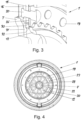
- the Fig. 2 to Fig. 4 show in enlarged illustrations further design details that enable an axial displacement of the output hub 12 and a related loosening of the toothing 23.
- the length of the stepped rivet 20 allows an axial displacement of the output hub 12 up to a complete separation of the toothing 23.
- the output hub 12 can be rotated until the openings 28 of the output hub 12 are in line with the holes 11 in the primary part 2 (shown in Fig. 1 ).
- the torsional vibration damper 1 can be easily dismantled, as the fastening screws can be loosened without the need for a special tool.
- the drive hub 12 is automatically pushed towards the sheet metal disc by the disc spring 22. 17 and shifted to lock into the gearing 23. Due to the changed positioning of the drive hub 12 relative to the primary part 2, a simplified reassembly of the torsional vibration damper 1 can also be carried out.
- Fig. 3 a section of the torsional vibration damper 1 is shown, which shows in particular the installation position of the externally toothed output hub 12.
- the Fig. 4 illustrates the design of the disc spring 22, which is partially supported by means of tabs 29 on six symmetrically circumferentially distributed stepped rivets 20.
- Fig. 5 and Fig. 6 illustrate an alternative embodiment of a torsional vibration damper 40 constructed according to the invention, wherein the components corresponding to the torsional vibration damper 1 are provided with the same reference numerals.
- the following description is largely limited to different embodiments.
- the torsional vibration damper 40 shows a centering of the secondary part 3 that is positioned radially offset in the direction of the axis of rotation 4 relative to the opening 28 of the output hub 12. Accordingly, the carrier ring 41 assigned to the primary part 2 is provided with a cranked section that receives the friction ring 42 and on which the output hub 12 is directly supported.
Landscapes
- Engineering & Computer Science (AREA)
- General Engineering & Computer Science (AREA)
- Physics & Mathematics (AREA)
- Acoustics & Sound (AREA)
- Aviation & Aerospace Engineering (AREA)
- Mechanical Engineering (AREA)
- Manufacturing & Machinery (AREA)
- Mechanical Operated Clutches (AREA)
Claims (10)
- Amortisseur de vibrations torsionnelles (1, 40) d'un véhicule automobile entraîné par un moteur à combustion interne, qui est réalisé sous la forme d'un volant bimasse et qui comprend une partie primaire (2) fixée à un vilebrequin et une partie secondaire (3) associée à un côté sortie, qui peuvent tourner ensemble autour d'un axe de rotation (4) et qui sont disposés de manière à pouvoir tourner l'un par rapport à l'autre et entre lesquels un dispositif amortisseur à ressort (5) est disposé dans le flux de couple, la partie secondaire (3) réalisée en plusieurs parties comprenant un limiteur de couple (13) dont le flasque de support (10) est couplé indirectement par l'intermédiaire d'au moins une garniture de friction (24, 25) et un disque de guidage (15) à un moyeu de sortie (12), un déplacement axial du moyeu de sortie (12) à l'encontre d'une force de ressort d'au moins un ressort à lames (22) libérant une denture (23) et interrompant une transmission du couple de l'amortisseur de vibrations torsionnelles (1, 40) et le moyeu de sortie (12) pouvant alors tourner jusqu'à ce que les ouvertures (28) du moyeu de sortie (12) coïncident avec des alésages (11) de la partie primaire (2), caractérisé en ce que le moyeu de sortie (12) d'une part vient directement ou indirectement axialement en appui sur un anneau de friction (30 , 42), l'anneau de friction (30, 42) étant associé à la partie primaire (2) par l'intermédiaire d'un anneau de support (31, 41) et le moyeu de sortie (12), d'autre part, est relié par complémentarité de forme, par l'intermédiaire de la denture (23), à un disque en tôle (17) situé en amont du disque de guidage (15), relié au disque de guidage et denté.
- Amortisseur de vibrations torsionnelles (1, 40) selon la revendication 1, caractérisé en ce que le limiteur de couple (13) présente un logement (14) délimité axialement au moyen de sections coudées opposées du disque de guidage (15) et d'un disque d'appui (16), logement qui est ouvert en direction du dispositif amortisseur à ressort (5), logement dans lequel sont insérés le flasque de support (10) et les garnitures de friction (24, 25).
- Amortisseur de vibrations torsionnelles (1, 40) selon la revendication 2, caractérisé en ce que le limiteur de couple (13) comprend des garnitures de friction (24, 25) en forme de disque, graissées ou huilées, positionnées de part et d'autre du flasque de support (10).
- Amortisseur de vibrations torsionnelles (1, 40) selon l'une quelconque des revendications 1 à 3, caractérisé en ce qu'une membrane à rondelle-ressort (26) est insérée entre le disque de guidage (15) et le disque en tôle denté (17), membrane qui vient radialement en appui à l'extérieur sur un couvercle primaire (8) de la partie primaire (2), par l'intermédiaire d'un disque de friction (27), et la membrane à rondelle-ressort (26) forme une section (32) située radialement à l'intérieur et recouvrant frontalement l'anneau de friction (30), sur laquelle section le moyeu de sortie (12) vient axialement en appui.
- Amortisseur de vibrations torsionnelles (1, 40) selon l'une quelconque des revendications 1 à 4, caractérisé en ce que le disque de guidage (15), le disque d'appui (16), la membrane à rondelle-ressort (26), le disque en tôle (17) et le moyeu de sortie (12) sont assemblés par l'intermédiaire de liaisons rivetées (18) avec des rivets (19) disposés circonférentiellement, au moins un rivet étant conçu comme un rivet goujon (20), sur la tête de rivet (21) duquel la rondelle-ressort (22) vient en appui.
- Amortisseur de vibrations torsionnelles (1, 40) selon l'une quelconque des revendications 1 à 5, caractérisé en ce que le moyeu de sortie (12) vient en e appui axialement et est centré, par l'intermédiaire de l'anneau de friction (42) en liaison avec un anneau de support (41) radialement en dessous des alésages (11) de la partie primaire (2).
- Amortisseur de vibrations torsionnelles (1, 40) selon la revendication 1 ou la revendication 6, caractérisé en ce que l'anneau de friction (30, 42) utilisé pour centrer le moyeu de sortie (12) est fixé à l'anneau de support (31, 41) de manière fixée en rotation et en position par liaison de matière et/ou par complémentarité de forme.
- Amortisseur de vibrations torsionnelles (1, 40) selon l'une quelconque des revendications 1 à 7, caractérisé en ce que l'amortisseur de vibrations torsionnelles (1, 40) avec limiteur de couple (13) intégré est prévu pour des applications hybrides, en particulier pour des applications hybrides DHT.
- Amortisseur de vibrations torsionnelles (1, 40) selon l'une quelconque des revendications 1 à 8, caractérisé en ce qu'au moins les composants de la partie secondaire (3) tels que le disque de guidage (15), le disque d'appui (16), le disque en tôle (17) et le moyeu de sortie (12) sont réalisés sous forme de pièce moulée ou de pièce estampée.
- Procédé de démontage et de montage d'un amortisseur de vibrations torsionnelles (1, 40), relié à un vilebrequin d'un moteur à combustion interne, selon l'une quelconque des revendications 1 à 9, caractérisé en ce que, après un déplacement axial du moyeu de sortie (12) à l'encontre une force élastique de la rondelle-ressort (22), le moyeu de sortie (12) peut être tourné dans une position, un démontage et/ou un remontage de l'amortisseur de vibrations torsionnelles (1, 40) pouvant intervenir lorsque les ouvertures (28) du moyeu de sortie (12) coïncident avec des alésages (11) dans la partie primaire (2), qui sont destinés à la fixation de l'amortisseur de vibrations torsionnelles (1, 40).
Applications Claiming Priority (2)
| Application Number | Priority Date | Filing Date | Title |
|---|---|---|---|
| DE102020100456 | 2020-01-10 | ||
| PCT/DE2020/100972 WO2021139849A1 (fr) | 2020-01-10 | 2020-11-16 | Amortisseur de vibrations torsionnelles équipé d'un limiteur de couple comportant des rivets goujons et des garnitures de friction humides |
Publications (2)
| Publication Number | Publication Date |
|---|---|
| EP4088042A1 EP4088042A1 (fr) | 2022-11-16 |
| EP4088042B1 true EP4088042B1 (fr) | 2025-01-08 |
Family
ID=73654588
Family Applications (1)
| Application Number | Title | Priority Date | Filing Date |
|---|---|---|---|
| EP20816892.2A Active EP4088042B1 (fr) | 2020-01-10 | 2020-11-16 | Amortisseur de vibrations torsionnelles équipé d'un limiteur de couple comportant des rivets goujons et des garnitures de friction humides,ainsi que le procédé d'installation correspondant |
Country Status (4)
| Country | Link |
|---|---|
| EP (1) | EP4088042B1 (fr) |
| CN (1) | CN114846253A (fr) |
| DE (2) | DE112020006489A5 (fr) |
| WO (1) | WO2021139849A1 (fr) |
Family Cites Families (12)
| Publication number | Priority date | Publication date | Assignee | Title |
|---|---|---|---|---|
| DE502006009337D1 (de) * | 2005-10-29 | 2011-06-01 | Schaeffler Technologies Gmbh | Drehschwingungsdämpfungseinrichtung |
| DE102012202255A1 (de) | 2011-02-23 | 2012-08-23 | Schaeffler Technologies AG & Co. KG | Drehschwingungsdämpfer |
| WO2014053128A1 (fr) * | 2012-10-01 | 2014-04-10 | Schaeffler Technologies AG & Co. KG | Amortisseur de vibrations de torsion et anneau de friction correspondant |
| DE112013005140A5 (de) * | 2012-10-25 | 2015-07-16 | Schaeffler Technologies AG & Co. KG | Drehschwingungsdämpfer |
| DE102015203475A1 (de) * | 2015-02-26 | 2016-09-01 | Schaeffler Technologies AG & Co. KG | Drehschwingungsdämpfer und Verfahren zu dessen Herstellung |
| FR3036754B1 (fr) * | 2015-06-01 | 2018-12-07 | Valeo Embrayages | Mecanisme d'embrayage et gamme de mecanismes d'embrayage |
| DE102016204261B4 (de) * | 2016-03-15 | 2019-10-17 | Schaeffler Technologies AG & Co. KG | Zweimassenschwungrad mit Drehmomentbegrenzung und einem verdrehbaren Lagerflansch |
| DE102018111161A1 (de) * | 2017-05-17 | 2018-11-22 | Schaeffler Technologies AG & Co. KG | Deckelloses Zweimassenschwungrad mit einem Fliehkraftpendel |
| DE102018111607A1 (de) * | 2017-06-02 | 2018-12-06 | Schaeffler Technologies AG & Co. KG | Drehschwingungsdämpfer |
| DE102017119375B4 (de) | 2017-08-24 | 2024-03-21 | Schaeffler Technologies AG & Co. KG | Drehschwingungsdämpfer |
| DE102018201534A1 (de) * | 2018-02-01 | 2019-08-01 | Zf Friedrichshafen Ag | Torsionsschwingungsdämpfer |
| DE102018103536A1 (de) * | 2018-02-16 | 2019-08-22 | Schaeffler Technologies AG & Co. KG | Zweimassenschwungrad mit einem abgedichteten Federkanal |
-
2020
- 2020-11-16 EP EP20816892.2A patent/EP4088042B1/fr active Active
- 2020-11-16 DE DE112020006489.1T patent/DE112020006489A5/de not_active Withdrawn
- 2020-11-16 CN CN202080088698.0A patent/CN114846253A/zh active Pending
- 2020-11-16 DE DE102020130110.3A patent/DE102020130110A1/de not_active Withdrawn
- 2020-11-16 WO PCT/DE2020/100972 patent/WO2021139849A1/fr not_active Ceased
Also Published As
| Publication number | Publication date |
|---|---|
| EP4088042A1 (fr) | 2022-11-16 |
| CN114846253A (zh) | 2022-08-02 |
| DE102020130110A1 (de) | 2021-07-15 |
| WO2021139849A1 (fr) | 2021-07-15 |
| DE112020006489A5 (de) | 2022-11-03 |
Similar Documents
| Publication | Publication Date | Title |
|---|---|---|
| DE102018119505A1 (de) | Drehmomentbegrenzer für einen Drehschwingungsdämpfer | |
| DE102017109439B4 (de) | Drehschwingungsdämpfer mit einer Drehmomentbegrenzung | |
| DE102016204261B4 (de) | Zweimassenschwungrad mit Drehmomentbegrenzung und einem verdrehbaren Lagerflansch | |
| DE102018103536A1 (de) | Zweimassenschwungrad mit einem abgedichteten Federkanal | |
| DE102017127525A1 (de) | Kompakte Drehmomentübertragungseinrichtung eines Hybridfahrzeugs | |
| DE102017115902A1 (de) | Drehmomentbegrenzer eines Drehschwingungsdämpfers mit Tellerfederscheiben | |
| DE102014208126A1 (de) | Drehscheibenschwingungsdämpfer | |
| DE102013223753A1 (de) | Hydrodynamischer Drehmomentwandler | |
| DE102009004719B4 (de) | Drehschwingungsdämpfer | |
| DE102013201269A1 (de) | Reibungskupplung mit Fliehkraftpendel | |
| DE102012210007A1 (de) | Drehschwingungsdämpfer in einem hybridischen Antriebsstrang | |
| EP3775612A1 (fr) | Amortisseur de vibrations de torsion | |
| DE102020100390A1 (de) | Drehschwingungsdämpfer mit integriertem Drehmomentbegrenzer | |
| EP4088042B1 (fr) | Amortisseur de vibrations torsionnelles équipé d'un limiteur de couple comportant des rivets goujons et des garnitures de friction humides,ainsi que le procédé d'installation correspondant | |
| DE102020111226A1 (de) | Drehschwingungsdämpfer mit abgeschirmtem Drehmomentbegrenzer | |
| DE102019107919A1 (de) | Hybrid-Dämpfer mit Drehmomentbegrenzer und Fliehkraftpendel | |
| DE102019110979A1 (de) | Drehschwingungsdämpfer | |
| EP4090860A1 (fr) | Amortisseur de vibrations de torsion et limiteur de couple | |
| DE102014211744A1 (de) | Drehschwingungsdämpfer | |
| DE102019133731B3 (de) | Kupplungsaggregat, insbesondere für ein Hybridmodul, zum gedämpften Ankuppeln einer Brennkraftmaschine an einem Antriebsstrang eines Kraftfahrzeugs | |
| DE102017119495A1 (de) | Drehschwingungsdämpfer und Verfahren zur Herstellung eines Drehschwingungsdämpfers | |
| DE102016223394A1 (de) | Zweimassenschwungrad mit sekundärseitiger Zusatzmasse | |
| DE102020122501A1 (de) | Drehschwingungsdämpfer | |
| DE102022116460B4 (de) | Drehmomentbegrenzungsvorrichtung | |
| DE102019133130A1 (de) | Torsionsschwingungsdämpfer mit Hebelfedern und einer Rückhalteeinrichtung |
Legal Events
| Date | Code | Title | Description |
|---|---|---|---|
| STAA | Information on the status of an ep patent application or granted ep patent |
Free format text: STATUS: UNKNOWN |
|
| STAA | Information on the status of an ep patent application or granted ep patent |
Free format text: STATUS: THE INTERNATIONAL PUBLICATION HAS BEEN MADE |
|
| PUAI | Public reference made under article 153(3) epc to a published international application that has entered the european phase |
Free format text: ORIGINAL CODE: 0009012 |
|
| STAA | Information on the status of an ep patent application or granted ep patent |
Free format text: STATUS: REQUEST FOR EXAMINATION WAS MADE |
|
| 17P | Request for examination filed |
Effective date: 20220810 |
|
| AK | Designated contracting states |
Kind code of ref document: A1 Designated state(s): AL AT BE BG CH CY CZ DE DK EE ES FI FR GB GR HR HU IE IS IT LI LT LU LV MC MK MT NL NO PL PT RO RS SE SI SK SM TR |
|
| DAV | Request for validation of the european patent (deleted) | ||
| DAX | Request for extension of the european patent (deleted) | ||
| P01 | Opt-out of the competence of the unified patent court (upc) registered |
Effective date: 20230523 |
|
| GRAP | Despatch of communication of intention to grant a patent |
Free format text: ORIGINAL CODE: EPIDOSNIGR1 |
|
| STAA | Information on the status of an ep patent application or granted ep patent |
Free format text: STATUS: GRANT OF PATENT IS INTENDED |
|
| INTG | Intention to grant announced |
Effective date: 20240620 |
|
| GRAS | Grant fee paid |
Free format text: ORIGINAL CODE: EPIDOSNIGR3 |
|
| GRAA | (expected) grant |
Free format text: ORIGINAL CODE: 0009210 |
|
| STAA | Information on the status of an ep patent application or granted ep patent |
Free format text: STATUS: THE PATENT HAS BEEN GRANTED |
|
| AK | Designated contracting states |
Kind code of ref document: B1 Designated state(s): AL AT BE BG CH CY CZ DE DK EE ES FI FR GB GR HR HU IE IS IT LI LT LU LV MC MK MT NL NO PL PT RO RS SE SI SK SM TR |
|
| REG | Reference to a national code |
Ref country code: GB Ref legal event code: FG4D Free format text: NOT ENGLISH |
|
| REG | Reference to a national code |
Ref country code: CH Ref legal event code: EP |
|
| REG | Reference to a national code |
Ref country code: DE Ref legal event code: R096 Ref document number: 502020010175 Country of ref document: DE |
|
| REG | Reference to a national code |
Ref country code: IE Ref legal event code: FG4D Free format text: LANGUAGE OF EP DOCUMENT: GERMAN |
|
| REG | Reference to a national code |
Ref country code: LT Ref legal event code: MG9D |
|
| REG | Reference to a national code |
Ref country code: NL Ref legal event code: MP Effective date: 20250108 |
|
| PG25 | Lapsed in a contracting state [announced via postgrant information from national office to epo] |
Ref country code: NL Free format text: LAPSE BECAUSE OF FAILURE TO SUBMIT A TRANSLATION OF THE DESCRIPTION OR TO PAY THE FEE WITHIN THE PRESCRIBED TIME-LIMIT Effective date: 20250108 |
|
| PG25 | Lapsed in a contracting state [announced via postgrant information from national office to epo] |
Ref country code: RS Free format text: LAPSE BECAUSE OF FAILURE TO SUBMIT A TRANSLATION OF THE DESCRIPTION OR TO PAY THE FEE WITHIN THE PRESCRIBED TIME-LIMIT Effective date: 20250408 |
|
| PG25 | Lapsed in a contracting state [announced via postgrant information from national office to epo] |
Ref country code: FI Free format text: LAPSE BECAUSE OF FAILURE TO SUBMIT A TRANSLATION OF THE DESCRIPTION OR TO PAY THE FEE WITHIN THE PRESCRIBED TIME-LIMIT Effective date: 20250108 |
|
| PG25 | Lapsed in a contracting state [announced via postgrant information from national office to epo] |
Ref country code: PL Free format text: LAPSE BECAUSE OF FAILURE TO SUBMIT A TRANSLATION OF THE DESCRIPTION OR TO PAY THE FEE WITHIN THE PRESCRIBED TIME-LIMIT Effective date: 20250108 |
|
| PG25 | Lapsed in a contracting state [announced via postgrant information from national office to epo] |
Ref country code: ES Free format text: LAPSE BECAUSE OF FAILURE TO SUBMIT A TRANSLATION OF THE DESCRIPTION OR TO PAY THE FEE WITHIN THE PRESCRIBED TIME-LIMIT Effective date: 20250108 |
|
| PG25 | Lapsed in a contracting state [announced via postgrant information from national office to epo] |
Ref country code: NO Free format text: LAPSE BECAUSE OF FAILURE TO SUBMIT A TRANSLATION OF THE DESCRIPTION OR TO PAY THE FEE WITHIN THE PRESCRIBED TIME-LIMIT Effective date: 20250408 Ref country code: IS Free format text: LAPSE BECAUSE OF FAILURE TO SUBMIT A TRANSLATION OF THE DESCRIPTION OR TO PAY THE FEE WITHIN THE PRESCRIBED TIME-LIMIT Effective date: 20250508 |
|
| PG25 | Lapsed in a contracting state [announced via postgrant information from national office to epo] |
Ref country code: HR Free format text: LAPSE BECAUSE OF FAILURE TO SUBMIT A TRANSLATION OF THE DESCRIPTION OR TO PAY THE FEE WITHIN THE PRESCRIBED TIME-LIMIT Effective date: 20250108 |
|
| PG25 | Lapsed in a contracting state [announced via postgrant information from national office to epo] |
Ref country code: PT Free format text: LAPSE BECAUSE OF FAILURE TO SUBMIT A TRANSLATION OF THE DESCRIPTION OR TO PAY THE FEE WITHIN THE PRESCRIBED TIME-LIMIT Effective date: 20250508 Ref country code: LV Free format text: LAPSE BECAUSE OF FAILURE TO SUBMIT A TRANSLATION OF THE DESCRIPTION OR TO PAY THE FEE WITHIN THE PRESCRIBED TIME-LIMIT Effective date: 20250108 |
|
| PG25 | Lapsed in a contracting state [announced via postgrant information from national office to epo] |
Ref country code: BG Free format text: LAPSE BECAUSE OF FAILURE TO SUBMIT A TRANSLATION OF THE DESCRIPTION OR TO PAY THE FEE WITHIN THE PRESCRIBED TIME-LIMIT Effective date: 20250108 Ref country code: GR Free format text: LAPSE BECAUSE OF FAILURE TO SUBMIT A TRANSLATION OF THE DESCRIPTION OR TO PAY THE FEE WITHIN THE PRESCRIBED TIME-LIMIT Effective date: 20250409 |
|
| PG25 | Lapsed in a contracting state [announced via postgrant information from national office to epo] |
Ref country code: SE Free format text: LAPSE BECAUSE OF FAILURE TO SUBMIT A TRANSLATION OF THE DESCRIPTION OR TO PAY THE FEE WITHIN THE PRESCRIBED TIME-LIMIT Effective date: 20250108 |
|
| PG25 | Lapsed in a contracting state [announced via postgrant information from national office to epo] |
Ref country code: SM Free format text: LAPSE BECAUSE OF FAILURE TO SUBMIT A TRANSLATION OF THE DESCRIPTION OR TO PAY THE FEE WITHIN THE PRESCRIBED TIME-LIMIT Effective date: 20250108 |
|
| REG | Reference to a national code |
Ref country code: DE Ref legal event code: R097 Ref document number: 502020010175 Country of ref document: DE |
|
| PG25 | Lapsed in a contracting state [announced via postgrant information from national office to epo] |
Ref country code: DK Free format text: LAPSE BECAUSE OF FAILURE TO SUBMIT A TRANSLATION OF THE DESCRIPTION OR TO PAY THE FEE WITHIN THE PRESCRIBED TIME-LIMIT Effective date: 20250108 |
|
| PG25 | Lapsed in a contracting state [announced via postgrant information from national office to epo] |
Ref country code: EE Free format text: LAPSE BECAUSE OF FAILURE TO SUBMIT A TRANSLATION OF THE DESCRIPTION OR TO PAY THE FEE WITHIN THE PRESCRIBED TIME-LIMIT Effective date: 20250108 Ref country code: CZ Free format text: LAPSE BECAUSE OF FAILURE TO SUBMIT A TRANSLATION OF THE DESCRIPTION OR TO PAY THE FEE WITHIN THE PRESCRIBED TIME-LIMIT Effective date: 20250108 |
|
| PG25 | Lapsed in a contracting state [announced via postgrant information from national office to epo] |
Ref country code: RO Free format text: LAPSE BECAUSE OF FAILURE TO SUBMIT A TRANSLATION OF THE DESCRIPTION OR TO PAY THE FEE WITHIN THE PRESCRIBED TIME-LIMIT Effective date: 20250108 |
|
| PG25 | Lapsed in a contracting state [announced via postgrant information from national office to epo] |
Ref country code: SK Free format text: LAPSE BECAUSE OF FAILURE TO SUBMIT A TRANSLATION OF THE DESCRIPTION OR TO PAY THE FEE WITHIN THE PRESCRIBED TIME-LIMIT Effective date: 20250108 |
|
| PLBE | No opposition filed within time limit |
Free format text: ORIGINAL CODE: 0009261 |
|
| STAA | Information on the status of an ep patent application or granted ep patent |
Free format text: STATUS: NO OPPOSITION FILED WITHIN TIME LIMIT |
|
| 26N | No opposition filed |
Effective date: 20251009 |
|
| PGFP | Annual fee paid to national office [announced via postgrant information from national office to epo] |
Ref country code: FR Payment date: 20251126 Year of fee payment: 6 |
|
| PG25 | Lapsed in a contracting state [announced via postgrant information from national office to epo] |
Ref country code: IT Free format text: LAPSE BECAUSE OF FAILURE TO SUBMIT A TRANSLATION OF THE DESCRIPTION OR TO PAY THE FEE WITHIN THE PRESCRIBED TIME-LIMIT Effective date: 20250108 |
|
| PGFP | Annual fee paid to national office [announced via postgrant information from national office to epo] |
Ref country code: DE Payment date: 20260101 Year of fee payment: 6 |