EP4088051B1 - Kurbelgehäusebelüftungssystem mit einer durchflusssteuervorrichtung für borddiagnostik - Google Patents
Kurbelgehäusebelüftungssystem mit einer durchflusssteuervorrichtung für borddiagnostik Download PDFInfo
- Publication number
- EP4088051B1 EP4088051B1 EP21738300.9A EP21738300A EP4088051B1 EP 4088051 B1 EP4088051 B1 EP 4088051B1 EP 21738300 A EP21738300 A EP 21738300A EP 4088051 B1 EP4088051 B1 EP 4088051B1
- Authority
- EP
- European Patent Office
- Prior art keywords
- check valve
- flow
- pressure differential
- port
- conduit
- Prior art date
- Legal status (The legal status is an assumption and is not a legal conclusion. Google has not performed a legal analysis and makes no representation as to the accuracy of the status listed.)
- Active
Links
Images






Classifications
-
- F—MECHANICAL ENGINEERING; LIGHTING; HEATING; WEAPONS; BLASTING
- F01—MACHINES OR ENGINES IN GENERAL; ENGINE PLANTS IN GENERAL; STEAM ENGINES
- F01M—LUBRICATING OF MACHINES OR ENGINES IN GENERAL; LUBRICATING INTERNAL COMBUSTION ENGINES; CRANKCASE VENTILATING
- F01M13/00—Crankcase ventilating or breathing
- F01M13/02—Crankcase ventilating or breathing by means of additional source of positive or negative pressure
- F01M13/021—Crankcase ventilating or breathing by means of additional source of positive or negative pressure of negative pressure
- F01M13/022—Crankcase ventilating or breathing by means of additional source of positive or negative pressure of negative pressure using engine inlet suction
- F01M13/023—Control valves in suction conduit
-
- F—MECHANICAL ENGINEERING; LIGHTING; HEATING; WEAPONS; BLASTING
- F01—MACHINES OR ENGINES IN GENERAL; ENGINE PLANTS IN GENERAL; STEAM ENGINES
- F01M—LUBRICATING OF MACHINES OR ENGINES IN GENERAL; LUBRICATING INTERNAL COMBUSTION ENGINES; CRANKCASE VENTILATING
- F01M11/00—Component parts, details or accessories, not provided for in, or of interest apart from, groups F01M1/00 - F01M9/00
- F01M11/10—Indicating devices; Other safety devices
-
- F—MECHANICAL ENGINEERING; LIGHTING; HEATING; WEAPONS; BLASTING
- F01—MACHINES OR ENGINES IN GENERAL; ENGINE PLANTS IN GENERAL; STEAM ENGINES
- F01M—LUBRICATING OF MACHINES OR ENGINES IN GENERAL; LUBRICATING INTERNAL COMBUSTION ENGINES; CRANKCASE VENTILATING
- F01M13/00—Crankcase ventilating or breathing
- F01M13/0011—Breather valves
-
- F—MECHANICAL ENGINEERING; LIGHTING; HEATING; WEAPONS; BLASTING
- F02—COMBUSTION ENGINES; HOT-GAS OR COMBUSTION-PRODUCT ENGINE PLANTS
- F02B—INTERNAL-COMBUSTION PISTON ENGINES; COMBUSTION ENGINES IN GENERAL
- F02B39/00—Component parts, details, or accessories relating to, driven charging or scavenging pumps, not provided for in groups F02B33/00 - F02B37/00
-
- F—MECHANICAL ENGINEERING; LIGHTING; HEATING; WEAPONS; BLASTING
- F02—COMBUSTION ENGINES; HOT-GAS OR COMBUSTION-PRODUCT ENGINE PLANTS
- F02D—CONTROLLING COMBUSTION ENGINES
- F02D41/00—Electrical control of supply of combustible mixture or its constituents
- F02D41/22—Safety or indicating devices for abnormal conditions
-
- F—MECHANICAL ENGINEERING; LIGHTING; HEATING; WEAPONS; BLASTING
- F02—COMBUSTION ENGINES; HOT-GAS OR COMBUSTION-PRODUCT ENGINE PLANTS
- F02M—SUPPLYING COMBUSTION ENGINES IN GENERAL WITH COMBUSTIBLE MIXTURES OR CONSTITUENTS THEREOF
- F02M25/00—Engine-pertinent apparatus for adding non-fuel substances or small quantities of secondary fuel to combustion-air, main fuel or fuel-air mixture
- F02M25/06—Engine-pertinent apparatus for adding non-fuel substances or small quantities of secondary fuel to combustion-air, main fuel or fuel-air mixture adding lubricant vapours
-
- F—MECHANICAL ENGINEERING; LIGHTING; HEATING; WEAPONS; BLASTING
- F02—COMBUSTION ENGINES; HOT-GAS OR COMBUSTION-PRODUCT ENGINE PLANTS
- F02M—SUPPLYING COMBUSTION ENGINES IN GENERAL WITH COMBUSTIBLE MIXTURES OR CONSTITUENTS THEREOF
- F02M35/00—Combustion-air cleaners, air intakes, intake silencers, or induction systems specially adapted for, or arranged on, internal-combustion engines
- F02M35/10—Air intakes; Induction systems
- F02M35/10209—Fluid connections to the air intake system; their arrangement of pipes, valves or the like
- F02M35/10222—Exhaust gas recirculation [EGR]; Positive crankcase ventilation [PCV]; Additional air admission, lubricant or fuel vapour admission
-
- F—MECHANICAL ENGINEERING; LIGHTING; HEATING; WEAPONS; BLASTING
- F16—ENGINEERING ELEMENTS AND UNITS; GENERAL MEASURES FOR PRODUCING AND MAINTAINING EFFECTIVE FUNCTIONING OF MACHINES OR INSTALLATIONS; THERMAL INSULATION IN GENERAL
- F16K—VALVES; TAPS; COCKS; ACTUATING-FLOATS; DEVICES FOR VENTING OR AERATING
- F16K15/00—Check valves
- F16K15/02—Check valves with guided rigid valve members
- F16K15/04—Check valves with guided rigid valve members shaped as balls
- F16K15/048—Ball features
-
- F—MECHANICAL ENGINEERING; LIGHTING; HEATING; WEAPONS; BLASTING
- F16—ENGINEERING ELEMENTS AND UNITS; GENERAL MEASURES FOR PRODUCING AND MAINTAINING EFFECTIVE FUNCTIONING OF MACHINES OR INSTALLATIONS; THERMAL INSULATION IN GENERAL
- F16K—VALVES; TAPS; COCKS; ACTUATING-FLOATS; DEVICES FOR VENTING OR AERATING
- F16K15/00—Check valves
- F16K15/02—Check valves with guided rigid valve members
- F16K15/06—Check valves with guided rigid valve members with guided stems
- F16K15/063—Check valves with guided rigid valve members with guided stems the valve being loaded by a spring
-
- F—MECHANICAL ENGINEERING; LIGHTING; HEATING; WEAPONS; BLASTING
- F16—ENGINEERING ELEMENTS AND UNITS; GENERAL MEASURES FOR PRODUCING AND MAINTAINING EFFECTIVE FUNCTIONING OF MACHINES OR INSTALLATIONS; THERMAL INSULATION IN GENERAL
- F16K—VALVES; TAPS; COCKS; ACTUATING-FLOATS; DEVICES FOR VENTING OR AERATING
- F16K15/00—Check valves
- F16K15/02—Check valves with guided rigid valve members
- F16K15/06—Check valves with guided rigid valve members with guided stems
- F16K15/063—Check valves with guided rigid valve members with guided stems the valve being loaded by a spring
- F16K15/066—Check valves with guided rigid valve members with guided stems the valve being loaded by a spring with a plurality of valve members
-
- F—MECHANICAL ENGINEERING; LIGHTING; HEATING; WEAPONS; BLASTING
- F16—ENGINEERING ELEMENTS AND UNITS; GENERAL MEASURES FOR PRODUCING AND MAINTAINING EFFECTIVE FUNCTIONING OF MACHINES OR INSTALLATIONS; THERMAL INSULATION IN GENERAL
- F16K—VALVES; TAPS; COCKS; ACTUATING-FLOATS; DEVICES FOR VENTING OR AERATING
- F16K15/00—Check valves
- F16K15/14—Check valves with flexible valve members
- F16K15/148—Check valves with flexible valve members the closure elements being fixed in their centre
-
- F—MECHANICAL ENGINEERING; LIGHTING; HEATING; WEAPONS; BLASTING
- F16—ENGINEERING ELEMENTS AND UNITS; GENERAL MEASURES FOR PRODUCING AND MAINTAINING EFFECTIVE FUNCTIONING OF MACHINES OR INSTALLATIONS; THERMAL INSULATION IN GENERAL
- F16K—VALVES; TAPS; COCKS; ACTUATING-FLOATS; DEVICES FOR VENTING OR AERATING
- F16K17/00—Safety valves; Equalising valves, e.g. pressure relief valves
- F16K17/02—Safety valves; Equalising valves, e.g. pressure relief valves opening on surplus pressure on one side; closing on insufficient pressure on one side
- F16K17/12—Safety valves; Equalising valves, e.g. pressure relief valves opening on surplus pressure on one side; closing on insufficient pressure on one side weight-loaded
-
- F—MECHANICAL ENGINEERING; LIGHTING; HEATING; WEAPONS; BLASTING
- F16—ENGINEERING ELEMENTS AND UNITS; GENERAL MEASURES FOR PRODUCING AND MAINTAINING EFFECTIVE FUNCTIONING OF MACHINES OR INSTALLATIONS; THERMAL INSULATION IN GENERAL
- F16K—VALVES; TAPS; COCKS; ACTUATING-FLOATS; DEVICES FOR VENTING OR AERATING
- F16K17/00—Safety valves; Equalising valves, e.g. pressure relief valves
- F16K17/36—Safety valves; Equalising valves, e.g. pressure relief valves actuated in consequence of extraneous circumstances, e.g. shock, change of position
-
- F—MECHANICAL ENGINEERING; LIGHTING; HEATING; WEAPONS; BLASTING
- F01—MACHINES OR ENGINES IN GENERAL; ENGINE PLANTS IN GENERAL; STEAM ENGINES
- F01M—LUBRICATING OF MACHINES OR ENGINES IN GENERAL; LUBRICATING INTERNAL COMBUSTION ENGINES; CRANKCASE VENTILATING
- F01M13/00—Crankcase ventilating or breathing
- F01M2013/0038—Layout of crankcase breathing systems
- F01M2013/0044—Layout of crankcase breathing systems with one or more valves
-
- F—MECHANICAL ENGINEERING; LIGHTING; HEATING; WEAPONS; BLASTING
- F01—MACHINES OR ENGINES IN GENERAL; ENGINE PLANTS IN GENERAL; STEAM ENGINES
- F01M—LUBRICATING OF MACHINES OR ENGINES IN GENERAL; LUBRICATING INTERNAL COMBUSTION ENGINES; CRANKCASE VENTILATING
- F01M13/00—Crankcase ventilating or breathing
- F01M2013/0077—Engine parameters used for crankcase breather systems
- F01M2013/0083—Crankcase pressure
-
- F—MECHANICAL ENGINEERING; LIGHTING; HEATING; WEAPONS; BLASTING
- F01—MACHINES OR ENGINES IN GENERAL; ENGINE PLANTS IN GENERAL; STEAM ENGINES
- F01M—LUBRICATING OF MACHINES OR ENGINES IN GENERAL; LUBRICATING INTERNAL COMBUSTION ENGINES; CRANKCASE VENTILATING
- F01M2250/00—Measuring
- F01M2250/60—Operating parameters
-
- F—MECHANICAL ENGINEERING; LIGHTING; HEATING; WEAPONS; BLASTING
- F02—COMBUSTION ENGINES; HOT-GAS OR COMBUSTION-PRODUCT ENGINE PLANTS
- F02D—CONTROLLING COMBUSTION ENGINES
- F02D2250/00—Engine control related to specific problems or objectives
- F02D2250/08—Engine blow-by from crankcase chamber
-
- F—MECHANICAL ENGINEERING; LIGHTING; HEATING; WEAPONS; BLASTING
- F02—COMBUSTION ENGINES; HOT-GAS OR COMBUSTION-PRODUCT ENGINE PLANTS
- F02D—CONTROLLING COMBUSTION ENGINES
- F02D41/00—Electrical control of supply of combustible mixture or its constituents
- F02D41/0002—Controlling intake air
- F02D41/0007—Controlling intake air for control of turbo-charged or super-charged engines
-
- F—MECHANICAL ENGINEERING; LIGHTING; HEATING; WEAPONS; BLASTING
- F16—ENGINEERING ELEMENTS AND UNITS; GENERAL MEASURES FOR PRODUCING AND MAINTAINING EFFECTIVE FUNCTIONING OF MACHINES OR INSTALLATIONS; THERMAL INSULATION IN GENERAL
- F16K—VALVES; TAPS; COCKS; ACTUATING-FLOATS; DEVICES FOR VENTING OR AERATING
- F16K2200/00—Details of valves
- F16K2200/20—Common housing having a single inlet, a single outlet and multiple valve members
- F16K2200/201—Common housing having a single inlet, a single outlet and multiple valve members of diverse type, size or shape
-
- F—MECHANICAL ENGINEERING; LIGHTING; HEATING; WEAPONS; BLASTING
- F16—ENGINEERING ELEMENTS AND UNITS; GENERAL MEASURES FOR PRODUCING AND MAINTAINING EFFECTIVE FUNCTIONING OF MACHINES OR INSTALLATIONS; THERMAL INSULATION IN GENERAL
- F16K—VALVES; TAPS; COCKS; ACTUATING-FLOATS; DEVICES FOR VENTING OR AERATING
- F16K2200/00—Details of valves
- F16K2200/20—Common housing having a single inlet, a single outlet and multiple valve members
- F16K2200/203—Common housing having a single inlet, a single outlet and multiple valve members in parallel
-
- F—MECHANICAL ENGINEERING; LIGHTING; HEATING; WEAPONS; BLASTING
- F16—ENGINEERING ELEMENTS AND UNITS; GENERAL MEASURES FOR PRODUCING AND MAINTAINING EFFECTIVE FUNCTIONING OF MACHINES OR INSTALLATIONS; THERMAL INSULATION IN GENERAL
- F16K—VALVES; TAPS; COCKS; ACTUATING-FLOATS; DEVICES FOR VENTING OR AERATING
- F16K2200/00—Details of valves
- F16K2200/40—Bleeding means in closed position of the valve, e.g. bleeding passages
- F16K2200/402—Bleeding means in closed position of the valve, e.g. bleeding passages arranged on the valve housing or seat
Definitions
- This application relates to a crankcase ventilation breach detection system having a constant restriction of flow in the normal flow direction and free flow in the opposite direction, more particularly, to such a system achieving the same with a tuned orifice and two check valves in a parallel configuration with flow in opposite directions.
- a gate valve In automotive engines, on/off operation of a vacuum generator and/or accessory is frequently controlled by a gate valve in which a rigid gate is deployed across a conduit to stop the flow of a fluid (in this exemplary application, air) through the valve.
- the gate is typically actuated by a solenoid and opened or closed in response to an electrical current applied to the solenoid coil.
- These solenoid-powered gate valves also tend to include a coil spring, diaphragm, or other biasing element which biases the gate towards an unpowered, 'normally open' or 'normally closed' position.
- the pressure in an engine crankcase is ideally maintained near atmospheric pressure (ATM pressure +/- 5 kPa). Furthermore, it is desirable to be able to detect any leak in the crankcase ventilation system (path from fresh air to the manifold, including all flow passageways and passageway connections) to ensure crankcase gasses are appropriately managed to avoid excessive pollutants being discharged into the atmosphere. In order to achieve these conditions, free flow (minimal restriction) of air into the crankcase is needed, which can be switched to a restricted opening, in order to conduct a pressure integrity check (and not create an excessively negative pressure in the crankcase).
- the gate valve approach while successful, is more expensive and takes up engine space.
- a more cost effective and compact system to enable the pressure integrity check of the crankcase ventilation system is desirable, especially one as disclosed herein that does not require any electrical connections to move an actuator, such as a solenoid, to operate a valve.
- CN 207131916 U discloses a load sensitive proportion multiple unit valve guide control with hydraulic pressure steady voltage attenuator.
- EP 074727 7 A1 discloses a method and apparatus for controlling relative movement such as rotary movement between a railway truck and a car body supported thereby to control truck hunting through application of reaction forces resisting such rotary movement which are effective primarily to resist higher velocity relative rotational movements.
- EP 0582859 A1 concerns a hydraulic control device, comprising at least one directional control valve which is connected to a pump and return line and from which at least one consumer line (leads to a hydraulic consumer, a fixed displacement pump supplying a pump line via a regulating valve, and a control-pressure circuit in which a control pressure dependent upon the load pressure in the consumer line can be controlled, the regulating valve of which can be acted upon on a closing-pressure side by the control pressure from the control circuit and by spring force as well as on an opening-pressure side by the pump pressure, has a hydraulic, mechanically preloaded, opening-movement damping device between the closing-pressure side and the control circuit, which opening-movement damping device can be automatically cut out if a predetermined pressure difference between the higher control pressure applied to the closing-pressure side and the lower control pressure prevailing in the control circuit is exceeded.
- DE 10060175 A1 discloses a damping unit has a single intake connection and located behind it a branch divides into two parallel conduits.
- the conduits contain opposite back pressure valves, and they are united in front of a single outlet connection.
- a throttle element e.g. a nozzle is located between the conduit connection point and the outlet connection.
- Conduits, seats for the valves, and the throttle are e.g. formed by bores in a rigid housing block.
- the present invention discloses a flow control device and a crankcase ventilation breach detection system of an internal combustion engine according to the appended claims.
- fluid means any liquid, suspension, colloid, gas, plasma, or combinations thereof.
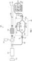
- FIG. 1 illustrates one embodiment of an engine system 100, which may be a vehicle engine system that is a turbocharged or supercharged system.
- the engine system 100 is configured for combusting fuel vapor accumulated in at least one component thereof and includes a multi-cylinder internal combustion engine 110.
- the engine system 100 receives air from an air intake 112, which may include an air filter 113 (also known as an air cleaner).
- the engine system of FIG. 1 is a turbocharged engine system having a turbocharger 114, but could just as equally be a supercharged engine system.
- the compressor 115 of the turbocharger 114 receives air from the air intake 112, compresses the air, and directs a flow of compressed air (or boosted air) downstream through a charge air cooler or intercooler 116 and then to a throttle 118.
- the throttle 118 controls fluid communication between the compressor 115 and the intake manifold 120 of the engine 110.
- the throttle 118 is operable using known techniques to vary an amount of intake air provided to the intake manifold 120 and the cylinders of the engine.
- the intercooler 116 may be positioned downstream of the throttle, and as such, may be housed in the intake manifold.
- intake manifold 120 is configured to supply intake air or an air-fuel mixture to a plurality of combustion chambers of engine 110 located within the engine block 122.
- the combustion chambers are typically arranged above a lubricant-filled crankcase 124 such that reciprocating pistons of the combustion chambers rotate a crankshaft (not shown) located in the crankcase 124. Unburned fuel and other combustion products may escape past each piston and/or valve guides from the engine block into the crankcase 124. The resulting gases in the crankcase, often referred to as "blow-by" gases may excessively pressurize the crankcase 124 if not vented therefrom.
- Engine 110 includes a crankcase ventilation system, which serves to vent blow-by gases from the crankcase 124 to intake manifold 120.
- the crankcase ventilation system includes a positive crankcase ventilation valve 126 in fluid communication between the crankcase 124 and the intake manifold 120, to regulate the flow of blow-by gases from the crankcase to the intake manifold, and a conduit known as a crankcase ventilation tube 128 placing the crankcase 124, in particular, the blow-by gas in fluid communication with clean air from the air intake 112.
- the crankcase ventilation tube 128 is in fluid communication upstream of the compressor 115.
- the crankcase ventilation tube 128 divides into a flow control system 130 that includes a pressure sensor 140 positioned between the flow control system 130 and the crankcase 124. In the flow control system detection of no pressure differential by the pressure sensor 140 indicates a breach in the system.
- the flow control system 130 in the embodiment of FIG. 1 and hence the flow control device 200 include three parallel conduits, one conduit 132 defines a restriction profile 133, another conduit 134 has a normally closed check valve 135 controlling flow therethrough from the air intake to the crankcase, and yet another conduit 136 has a normally neutral check valve 139 controlling flow therethrough from the crankcase to the air intake.
- the normally closed check valve 135 opens under a first preselected pressure differential
- the second check valve opens under a second preselected pressure differential
- the restriction profile has a third preselected pressure differential that is the same in either direction of flow therethrough.
- a first direction D 1 (the normal flow direction) is from the air intake upstream of the compressor to the crankcase and the second direction D 2 is the opposite of the first direction.
- Flow in the first direction D 1 through the flow control device 200 is through the open hemispherical poppet check valve as shown by the arrows in FIG. 4 .
- Flow in the second direction D 2 through the flow control device 200 is through the open normally neutral check valve as shown by the arrows in FIG. 5 .
- a "normally closed” check valve is in the closed position until the pressure differential (change in pressure) between the inlet and the outlet is sufficient to overcome the spring holding the poppet in the closed position.
- a "normally neutral” check valve is neither open nor closed and depends on sufficient pressure differential to overcome the minimal mass of the disc to be in either the open or closed position, depending on the flow direction.
- the normally closed check valve 135 can be tuned to open within 1 kPa to 2 kPa of the preselected pressure differential of a control system for a particular engine system based on the setpoints selected for said engine system. In one embodiment, the preselected pressure differential is a change of about 2.5 kPa. When used as a "normally closed” check valve the opening pressure differential can be tuned by varying the spring rate and preselected spring force at installation of the spring.
- the flow control system of FIG. 1 is set to have the first preselected pressure differential of the normally closed check valve 135 greater than or equal to the third pressure differential of the restrictor 133, and the second pressure differential of the normally neutral check valve 139 is the same or less than the third pressure differential of the restrictor 133.
- the first, second and third pressure differentials are in a range of about 1.5 kPa to about 4 kPa, more preferably about 2.5 kPa to about 3.5 kPa. "About" herein means +/- 0.3 kPa.
- the normally closed check valve 135 opens at about a 2.5 kPa pressure differential at 15 slpm and at about a 3.5 kPa pressure differential at 30 slpm, while the normally neutral check valve 139 opens at about a 0.1 kPa pressure differential at 15 slpm and at about a 0.4 kPa pressure differential at 30 slpm, with the restrictor orifice being continuously open and constructed for a 2.5 kPa pressure differential at 15 slpm.
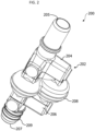
- a first embodiment of a flow control device 200 has a housing 202 having a first housing portion 204 defining a first port 205 and a second housing portion 206 defining a second port 207 that are sealingly fixed together with a fluid-tight seal at flange 208 and collectively define an internal cavity 210.
- the first port 205 and the second fluid port 207 are both in fluid communication with the internal cavity 210.
- the internal cavity 210 has larger dimensions than the first port 205 and the second port 207 and splits into three parallel conduits 132, 134, 136 each of which are in fluid communication with the first port 205 and the second port 207.
- first port 205 and the second port 207 are positioned opposite one another to define a generally linear flow path through the flow control device 200, but is not limited to this configuration.
- first and second ports may be positioned relative to one another at an angle of less than 180 degrees.
- Each of the exterior ends of the first port 205 and the second port 207 can include connecting features 209, such as flanges, ribs, grooves, barbs, etc. to attach a hose thereto or a duct of a device within the engine system.
- the first port 205 may include a sensor port 211 for a sensor such as a pressure sensor to detect changes in pressure that will indicate a leak in the engine system. Alternately, a sensor may be placed in the system between the first port and the crankcase.
- the first conduit 132 defining the restrictor 133 is generally positioned centrally in the flow control device 200 between the normally closed check valve 135 and the normally neutral check valve 139.
- the first conduit 132 is aligned with the first port 205 and the second port 207 along a central longitudinal axis A of the housing.
- the first conduit 132 may be molded of a suitable plastic separately from the first housing portion 204 and the second housing portion 206 and is inserted therein in registration therewith using mating registration features 147, 148.
- the restrictor 133 has an internal profile having upstream and downstream portions 142, 144 converging toward one another and defining a throat 146 where the two meet.
- Both portions 142, 144 are circular, when viewed in a transverse cross-section, and each narrow according to a parabolic or hyperbolic function along its length, which meet at the throat 146.
- the internal profile of the upstream and downstream portions 142, 144 may be symmetrical, mirror image of one another.
- the throat diameter is the parameter that determines or sets the maximum mass flow rate. A larger diameter for the throat equates to a larger mass flow rate.
- the throat diameter is in a range of about 2 mm to 5 mm, more preferably about 2 mm to about 3 mm. For the throat diameter, "about” means +/- 0.1 mm.
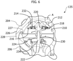
- the normally closed check valve 135 is a hemispherical poppet check valve that is spring biased into the closed position as illustrated in FIG. 3 and FIGS. 6-9 .
- the hemispherical poppet check valve 135 has an internal cavity 210 defined by the fluid tight connection of the first housing portion 204 and the second housing portion 206.
- the internal cavity 210 is generally spherically shaped and defines an annular seat 212 for engagement with a hemispherical poppet sealing member 214, which is translatable between a closed position against the annular seat 212 ( FIGS. 3 and 5-6 ) and an open position ( FIG. 4 ).
- the generally spherical shape of the internal cavity 210 complements the shape of the hemispherical poppet sealing member 214 and provides a low restriction flow path in the open position.
- the annular seat 212 in a longitudinal cross-section through the check valve 135, as shown in FIG. 6 , defines a convex spherical radius as indicated by arrow 213 in FIG. 7 .
- the convex spherical radius of the annular seat 212 is preferably positioned or formed at a transition from the first port 205 into the internal cavity 210.
- the internal cavity 210 has a generally spherical shape as noted above and, in the closed position, a convex surface of the hemispherical poppet sealing member 214 as indicated by arrow 215 in FIG. 7 is engaged with the convex spherical radius 213 of the annular seat 212.
- the convex surface-convex surface seal is shown as an enlarged image. This seal forms a tangent seal interface that is insensitive to slight misalignment of the hemispherical poppet sealing member 214 when closing. A slightly misaligned hemispherical poppet sealing member will still have good seal integrity, approximately 0.5 scc/m or less.
- the interior of the first housing portion 204 has, in a longitudinal cross-section, a partial "S" shaped curve centered about the convex spherical radius 213 that defines gaps 240, 242 between the hemispherical poppet sealing member and the housing above and below the convex surface-convex surface seal, based on the orientation of the figure to the page.
- the internal cavity 210 has a pin 222 centrally positioned and protruding into the cavity opposite the annual seat 212.
- the hemispherical poppet valve 214 has a cupped underside 216 defining a first seat 218 for the spring 230 and has a hollow stem 220 protruding from the cupped underside 216 toward the pin 222 and receives the pin 222 therein for translation of the hemispherical poppet sealing member 214 along the pin 222.
- a first end 232 of the spring 230 is seated and retained by first seat 218 in the cupped underside 216 of the hemispherical poppet sealing member 214 and a second end 234 of the spring 230 is seated and retained be a second seat 224 defined by the second housing portion 206 and protruding into the internal cavity proximate a base 223 of the pin 222.
- the cupped underside 216 of the hemispherical poppet sealing member 214 provides a large restriction to fluid flow in the "non-flow direction" represented by the arrows in FIG. 5 , thereby producing sufficient force to translate the sealing member to the closed position, even without the spring force provided by the spring, if desired.
- one or both of the annular seat 212 and the hemispherical poppet sealing member 214 can include a ring of elastomeric sealing material 260 ( FIG. 7 ) to define the convex spherical radius 213 of the annular seat 212 or to define the portion of the convex surface 262 of the hemispherical poppet sealing member 214 ( FIGS. 8 and 9 ) that engages the annular seat 212 in the closed position.
- a ring of elastomeric sealing material is not required.
- the ring of elastomeric sealing material 260 matches (is flush with) the partial "S" shaped curved contour of the first housing portion 204 so as not to create a flow restriction, in the open position and the ring of elastomeric sealing material 262 matches (is flush with) the hemispherical surface of the hemispherical poppet sealing member 214 so as not to create a flow restriction, in the open position.
- the ring of elastomeric sealing material 260, 262 is insert molded or co-molded as part of one or both of the annular seat 212, i.e., first housing portion 204, and the hemispherical poppet sealing member 214. Either or both of the rings of elastomeric sealing material 260, 262 may include an annular lip 264 best seen in FIG. 7 to help retain the molded elastomeric sealing material 260, 262 in place in its respective member.
- the ring of elastomeric sealing material may be formed of a fluoroelastomer.
- Suitable fluoroelastomers include, but are not limited to, polyvinyl fluoride, polyvinylidene fluorides, polytrifluoromonochloroethylene, polytetrafluoroethylene, polyhexafluoropropylene, polydifluoroethylene, polytetrafluoroethylene, fluorosilicone, ethylene-tetrafluoroethylene copolymer, hexafluoropropylene-tetrafluoroethylene copolymer, hexafluoropropylene-difluoroethylene copolymer, perfluoroalkoxytetrafluoroethylene copolymer, tetrafluoroethylene-hexafluoropropylene-vinylidene fluoride terpolymer, or other commercially available elastomeric material that will provide seal integrity at both low pressure differentials (such as
- the hemispherical poppet sealing member 214 has a cupped underside 216 defining an outer rim 217.
- the outer rim 217 can include an elastomeric flange 219 extending radially outward that, in the closed positioned, forms a clearance fit or an interference fit with a surface of the internal cavity 210. This elastomeric flange 219 enhances the ability of the hemispherical poppet sealing member 214 to close under low reverse flow conditions.
- the elastomeric flange 219 is insert molded or co-molded to the hemispherical poppet sealing member 214 and may include a head 221 inserted into the hemispherical poppet sealing member 214 as shown in FIG. 8 .
- the elastomeric flange 219 as shown in FIG. 9 may include a hinge feature 223 that allows the elastomeric flange 219 to bend out of the way in response to the pressure differentials in the system to maintain minimal restrictions on the fluid flow through the check valve in the open position, i.e., the flange 219 bends away from the surface of the internal cavity 210 toward the stem 220 and the pin 222.
- the first housing portion 204 terminates away from the first port 205 with a double flanged end 226, wherein an interior flange 227 of the double flange is shorter than an exterior flange 208 of the double flange and the interior flange 227 is contoured to lie radially inward of a rim 228 of the second housing portion 206 to collectively define the generally spherical shape of the internal cavity 210.
- the spherical radius and/or the radial position of spherical radius center of the first housing portion's profile is slightly less than the spherical radius and/or the radial position of spherical radius center of the second housing portion's profile, which creates an "overlap" of the interior flange 227 with the rim 228 described above and provides a low restriction flow path as well as low audible noise in the check valve 135.
- the exterior flange 208 of the first housing portion 204 and the rim 228 of the second housing portion 206 can have a snap-fit connection 250 as shown in FIG. 8 .
- the first housing portion 204 and the second housing portion 206 can be formed of a plastic material suitable for combustion engine environments and can be spin-welded together.
- the double flange end 226 of the first housing portion 204 can include an annular bead of sealing material 252 between the interior flange 227 and the exterior flange 208 to provide additional material for the spin weld.
- the open end 272 of the stem 220 and the head 274 of the pin 222 can have snap-fit features 270 to assist in maintaining the position of the hemispherical poppet sealing member 214 during assembly of the check valve 135.
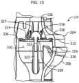
- the normally neutral check valve 139 has an internal cavity 310 defined within the third conduit 136 formed by the fluid tight connection of the first housing portion 204 to the second housing portion 206.
- the normally neutral check valve 139 has a pin 322 defined by one of the first or second housing portions 204, 206 and the other housing portion defines a sleeve 323 in which the pin 322 is received when the first and second housing portions are mated together.
- the sealing disk 336 has a central bore 339 therethrough that receives the pin 322 such that the sealing disc 336 is seated upon the pin 322.
- the sealing disc 336 floats and translates along the pin 322 between an open position and a closed position based on pressure differentials in the system.
- the sealing disc 336 is not a spring biased sealing member.
- the portion of the housing 202 defining the internal cavity 310 includes an internal first seat 312, here collectively a first annular seal bead 314 and a second annular seal bead 316, upon which the sealing disc 336 seats when the check valve is "closed," as shown in FIGS. 4 and 10 .
- the second annular seal bead 316 is radially inward of the first annular seal bead 314.
- a second seat 318 is defined by a plurality of radially spaced fingers 320 extending into the internal cavity 310 from an interior surface of the internal cavity that is more proximate the second port 207 and the air box of the engine system.
- the plurality of radially spaced apart fingers 320 have a pre-selected length that provides a distance between the first seat 312 and the second seat 318, thereby enabling the sealing disc 336 to translate along the pin from the closed position to the open position. In the open position the sealing disc 336 is elastically flexed against the plurality of radially spaced fingers 320 as shown in FIG. 5 .
- the pin 322 is typically centrally positioned within the internal cavity 310 and a plurality of ribs 326 comprising connecting ribs and/or partial ribs 327 as disclosed in any of the configurations disclosed in U.S. patent 10,107, 240 extend radially outward from the pin 322 or toward the pin 322 to subdivide the flow path into a plurality of conduits to direct the fluid flow around the periphery of the sealing disk 336 as shown by the arrows in FIG. 5 when the check valve 200 is elastically flexed in the open position.
- the sealing disk 336 can have a constant thickness across its diameter as illustrated in the figures, thereby being a flat planar disc, or it can be a stepped disk as described in co-owned patent U.S. 10,107,240 .
- the sealing disc 336 is elastically flexible to bend toward the second seat 318 in response to a preselected pressure differential across the normally neutral check valve 139.
- the sealing disc 336 transforms between a flat shape in the closed position to a shallow bowl shape in the open position and back again.
- the sealing disc 336 readily flexes when there is a pressure differential from the side of the first seat 312 to the second seat 318, i.e., higher pressure is at the first seat 312.
- the sealing disc 336 may be or include an elastomeric material suitable for use in fluid communication with blow-by-gas from the crankcase ventilation system of an internal combustion engine, i.e., is durable when exposed to temperatures and pressures associated with such an environment.
- the sealing disc 336 may be or include one or more of a natural rubber, synthetic rubber, silicone rubber, fluorosilicone rubber, fluorocarbon rubber, nitrile rubber, EPDM, PTFE, and combinations thereof, but is not limited thereto.
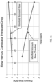
- FIG. 11 the graph of the flow rate versus the pressure drop experienced at the crankcase shows that in manifold vacuum there is a detectable amount of pressure drop to meet diagnostic requirements, but minimal increase in pressure drop as flow increases so as not to cause engine damage, while in manifold boost there is minimal pressure drop as desired. This allows diagnostic compliance anytime there is manifold vacuum.
- a second embodiment of a flow control device generally designated 300, has a housing 302 having a first housing portion 304 defining a first port 305 and a second housing portion 306 defining a second port 307 that are sealingly fixed together with a fluid-tight seal at flange 308 and collectively define an internal cavity 310.
- the first port 305 and the second fluid port 307 are both in fluid communication with the internal cavity 310.
- the internal cavity 310 has larger dimensions than the first port 305 and the second port 307 and splits into three parallel conduits 132, 134, 136, each of which are in fluid communication with the first port 305 and the second port 307.
- the first conduit 132 defines a restriction profile 133
- the second conduit 134 has a normally closed check valve 135 controlling flow therethrough from the air intake to the crankcase
- the third conduit 136 has a normally neutral check valve 139 controlling flow therethrough from the crankcase to the air intake.
- the normally closed check valve 135 opens under a first preselected pressure differential
- the second check valve opens under a second preselected pressure differential
- the restriction profile has a third preselected pressure differential that is the same in either direction of flow therethrough.
- Flow in the first direction D 1 from the air box to the intake manifold, through the flow control device 300 is through the open hemispherical poppet check valve as shown by the arrows in FIG. 13 .
- first port 305 and the second port 307 are positioned opposite one another to define a generally linear flow path through the flow control device 300, but are not limited to this configuration.
- first and second ports may be positioned relative to one another at an angle of less than 180 degrees.
- Each of the exterior ends of the first port 305 and the second port 307 can include connecting features, such as flanges, ribs, grooves, barbs, etc. to attach a hose thereto or a duct of a device within the engine system.
- the second port 307 includes a connecting feature 309, a cap for permanent connection to a duct of a device within the engine system, such as the air box.
- the cap 309 has a dual flanged terminal end 312 which receives a rim of the duct between the flanges.
- the dual flanged terminal end 312 lends itself to spin-welding the flow control device 300 to the duct.
- the dual flanged terminal end can be attached to the duct by adhesive, other forms of welding, such as vibration welding or induction welding, heat-bonding, laser-bonding, or other methods known for mating plastic components in engine systems.
- the first port 305 includes a sensor port 311 for a sensor such as a pressure sensor 350, shown in FIG. 15 , to detect changes in pressure that will indicate a leak in the engine system.
- the pressure sensor 350 includes an electrical plug 352 for connection to an electrical source.
- the sensor portion of the pressure sensor 350 is in fluid communication with the sensor port 311 to be able to sense or measure parameters of the fluid and/or fluid flow within the flow control device.
- the first conduit 132 defining the restrictor 133 is generally positioned centrally in the flow control device 300 between the normally closed check valve 135 and the normally neutral check valve 139. As described above for the first embodiment, the first conduit 132 is aligned with the first port 305 and the second port 207 along a central longitudinal axis A of the housing.
- the first conduit 132 may be molded of a suitable plastic separately from the first housing portion 304 and the second housing portion 306 and is inserted therein in registration therewith using mating registration features 147, 148.
- the restrictor 133 has the same characteristics, internal profile, and parameters described above.
- the normally closed check valve 135 is a hemispherical poppet check valve that is spring biased into the closed position as illustrated in FIG. 3 and FIGS. 6-9 .
- the hemispherical poppet check valve 135 has an internal cavity 210 defined by the fluid tight connection of the first housing portion 204 and the second housing portion 206.
- the internal cavity 210 is generally spherically shaped and defines an annular seat 212 for engagement with a hemispherical poppet sealing member 214, which is translatable between a closed position against the annular seat 212 ( FIGS. 3 and 5-6 ) and an open position ( FIG. 4 ).
- the generally spherical shape of the internal cavity 210 complements the shape of the hemispherical poppet sealing member 214 and provides a low restriction flow path in the open position.
- the annular seat 212 in a longitudinal cross-section through the check valve 135, as shown in FIG. 6 , defines a convex spherical radius as indicated by arrow 213 in FIG. 7 .
- the convex spherical radius of the annular seat 212 is preferably positioned or formed at a transition from the first port 205 into the internal cavity 210.
- the internal cavity 210 has a generally spherical shape as noted above and, in the closed position, a convex surface of the hemispherical poppet sealing member 214 as indicated by arrow 215 in FIG. 7 is engaged with the convex spherical radius 213 of the annular seat 212.
- the flow control devices have a housing that is typically molded of plastic, such as, but not limited to, nylon 6, nylon 4/6, nylon 6/6 and/or polyoxymethylene.
- the sealing members of the check valve may be constructed of a fluoroelastomer.
- Suitable fluoroelastomers include, but are not limited to, polyvinyl fluoride, polyvinylidene fluorides, polytrifluoromonochloroethylene, polytetrafluoroethylene, polyhexafluoropropylene, polydifluoroethylene, polytetrafluoroethylene, fluorosilicone, ethylene-tetrafluoroethylene copolymer, hexafluoropropylene-tetrafluoroethylene copolymer, hexafluoropropylene-difluoroethylene copolymer, perfluoroalkoxytetrafluoroethylene copolymer, tetrafluoroethylene-hexafluoropropylene-vinylidene fluoride terpolymer, or other commercially available elastomeric material that will provide seal integrity at both low pressure differentials (such as 5 kPa) and at high pressure differentials (such as 200 kPa), and blends thereof.
- the flow control device is constructed of materials suitable for operation under a pressure range of 101 kPa to -80kPa and a temperature range of -40°C to 120°C.
- the flow control device is typically about 100 mm to about 200 mm in length, more preferably about 100 mm to about 150 mm in length.
- the advantages and/or benefits of the flow control device include a simplified design of reduced size that does not require electromotive controls (i.e., it is a passive device) for either check valve and reduces the number of hose connection points.
- the reduced number of connections eliminates costs and potential leak points.
- the flow control devices has a tunable normally closed check valve (adjust the spring, i.e., the spring force applied to the poppet sealing member) and a tunable restrictor by preselecting an orifice size suitable for the engine system, and customizable end connector sizes and styles, for example an end that connects permanently to the air box as shown in FIGS. 12-15 .
- the spring can be tuned to open at a higher or lower pressure differential for different engine sizes.
- the flow control device provides the advantage of enabling a pressure sensor to continuously check for leaks up- and down-stream of the flow control device due to constant flow through the restrictor's preselected orifice size. If the normally closed check valve does not open, the pressure sensor will sense an increased vacuum level, which will cause an error detection. And, if the normally neutral check valve fails to open, the pressure sensor will sense a higher pressure, which will cause an error detection.
- the hemispherical poppet check valve provides additional advantages to the flow control device, such as a check valve that opens under low differential pressure and has low flow restriction once open.
- the low flow restriction in the open position is a result of the combined shapes of the generally spherical internal cavity and the upper surface of the hemispherical poppet sealing member (see the flow arrows in FIG. 3 ), more particularly, the internal flange of the first housing portion overlapping the rim of the second housing portion and defining matching contours once sealingly fixed together.
- This configuration also provides low audible noise when open and a no-leak seal when closed.
- Another advantage is that the check valve is not sensitive to the orientation of the flow control device in an engine system because the hemispherical poppet sealing member has a low mass, and does not move to the closed or open position under its own mass.
Landscapes
- Engineering & Computer Science (AREA)
- General Engineering & Computer Science (AREA)
- Mechanical Engineering (AREA)
- Chemical & Material Sciences (AREA)
- Combustion & Propulsion (AREA)
- Check Valves (AREA)
- Lubrication Details And Ventilation Of Internal Combustion Engines (AREA)
Claims (13)
- Durchflusssteuervorrichtung (200), umfassend:
ein Gehäuse (202), das eine Vielzahl von parallelen Leitungen (132, 134, 136) definiert, umfassend:eine erste Leitung (132), die ein normalerweise geschlossenes Rückschlagventil (135) aufweist, das den Durchfluss durch die erste Leitung (132) steuert, wobei sich das normalerweise geschlossene Rückschlagventil (135) unter einer ersten vorgewählten Druckdifferenz in einer ersten Richtung (D1) von Durchfluss öffnet;eine zweite Leitung (134), die ein normalerweise neutrales Rückschlagventil (139) aufweist, das sich unter einer zweiten vorgewählten Druckdifferenz in einer zweiten Richtung (D2) von Durchfluss öffnet, die der ersten Richtung (D1) von Durchfluss entgegengesetzt ist; undeine dritte Leitung (136), die ein Einschränkungsprofil definiert, das kontinuierlich geöffnet ist und eine dritte vorgewählte Druckdifferenz aufweist;dadurch gekennzeichnet, dassdie Durchflusssteuervorrichtung (200) einen ersten Anschluss (205) in Fluidkommunikation mit allen der Vielzahl von parallelen Leitungen (132, 134, 136) aufweist und einen Sensoranschluss (211) in dem ersten Anschluss (205) für eine Verbindung mit einem Drucksensor (350) und einen Drucksensor (350) definiert, der mit dem Sensoranschluss (211) wirkverbunden ist. - Vorrichtung nach Anspruch 1, wobei die erste vorgewählte Druckdifferenz größer als die dritte vorgewählte Druckdifferenz ist.
- Vorrichtung nach Anspruch 1, wobei die zweite vorgewählte Druckdifferenz gleich oder niedriger als die erste vorgewählte Druckdifferenz ist.
- Vorrichtung nach Anspruch 1, wobei die erste vorgewählte Druckdifferenz größer als die dritte Druckdifferenz ist und die zweite Druckdifferenz gleich oder niedriger als die dritte Druckdifferenz ist.
- Vorrichtung nach Anspruch 1, wobei die Durchflusssteuervorrichtung (200) einen zweiten Anschluss (307) in Fluidkommunikation mit allen der Vielzahl von parallelen Leitungen (132, 134, 136) aufweist, und der zweite Anschluss (307) als eine Kappe (309) geformt ist, die dauerhaft an einem Lufteinlass (112) befestigt werden kann.
- Vorrichtung nach Anspruch 1, wobei das normalerweise geschlossene Rückschlagventil (135) ein halbkugelförmiges Tellerrückschlagventil (135) und eine Feder (230) umfasst, die das halbkugelförmige Tellerdichtelement (214) in eine geschlossene Position vorspannt.
- Vorrichtung nach Anspruch 6, wobei das halbkugelförmige Tellerrückschlagventil (135) in der geschlossenen Position eine konvexe Oberfläche (262) des halbkugelförmigen Tellerdichtelements (214) gegen eine konvexe Oberfläche (262) der ersten Leitung (132) lagert.
- Vorrichtung nach Anspruch 1, wobei das normalerweise neutrale Rückschlagventil (139) eine Dichtscheibe (336) umfasst, die ausschließlich als Reaktion auf eine Druckdifferenz in der zweiten Leitung (134) zwischen einer geöffneten Position und einer geschlossenen Position verschiebbar ist, und wobei die Dichtscheibe (336) flexibel ist und in der geöffneten Position schüsselförmig ist und in der geschlossenen Position flach ist.
- System für eine Erkennung einer Verletzung einer Kurbelgehäuseentlüftung eines Verbrennungsmotors, umfassend:einen Verbrennungsmotor, der ein Kurbelgehäuse (124) und einen Ansaugkrümmer (120) aufweist;ein Ventil (126) für eine positive Kurbelgehäuseentlüftung in Fluidkommunikation zwischen dem Kurbelgehäuse (124) und dem Ansaugkrümmer (120), um den Durchfluss von Blow-by-Gas von dem Kurbelgehäuse (124) zu dem Ansaugkrümmer (120) zu regulieren;ein Kurbelgehäuseentlüftungsrohr (128) in Fluidkommunikation mit Luft von einem Lufteinlass (112) und dem Blow-by-Gas;eine Durchflusssteuervorrichtung (200), umfassend:
ein Gehäuse (202), das eine Vielzahl von parallelen Leitungen (132, 134, 136) definiert, umfassend:eine erste Leitung (132), die ein normalerweise geschlossenes Rückschlagventil (135) aufweist, das den Durchfluss durch die erste Leitung (132) steuert, wobei sich das normalerweise geschlossene Rückschlagventil (135) unter einer ersten vorgewählten Druckdifferenz in einer ersten Richtung (D1) von Durchfluss öffnet; eine zweite Leitung (134), die ein normalerweise neutrales Rückschlagventil (139) aufweist, das sich unter einer zweiten vorgewählten Druckdifferenz in einer zweiten Richtung (D2) von Durchfluss öffnet, die der ersten Richtung (D1) von Durchfluss entgegengesetzt ist; undeine dritte Leitung (136), die ein Einschränkungsprofil definiert, das kontinuierlich geöffnet ist und eine dritte vorgewählte Druckdifferenz aufweist, wobei die erste Richtung (D1) von Durchfluss von dem Lufteinlass (112) zu dem Kurbelgehäuse (124) verläuft und die zweite Richtung (D2) von Durchfluss von dem Kurbelgehäuse (124) zu dem Lufteinlass (112) verläuft; undeinen Drucksensor (350), der zwischen den parallelen Leitungen (132, 134, 136) und dem Kurbelgehäuse (124) positioniert ist, wobei die Erkennung einer fehlenden Druckdifferenz durch den Drucksensor (350) eine Verletzung in dem System anzeigt. - System nach Anspruch 9, wobei der Verbrennungsmotor einen Turbolader (114) aufweist und das Kurbelgehäuseentlüftungsrohr (128) stromaufwärts des Kompressors (115) des Turboladers (114) verbunden ist.
- System nach Anspruch 9, wobei der Drucksensor (350) erhöhte Vakuumniveaus erkennt, falls das normalerweise geschlossene Rückschlagventil (135) nicht öffnet und einen Fehler anzeigt, und der Drucksensor (350) einen höheren als den normalen Druck erkennt, falls das normalerweise neutrale Rückschlagventil (139) nicht öffnet und einen Fehler anzeigt.
- System nach Anspruch 9, wobei die Durchflusssteuervorrichtung (200) einen ersten Anschluss (205) in Fluidkommunikation mit allen der Vielzahl von parallelen Leitungen (132, 134, 136) aufweist und einen Sensoranschluss (211) in dem ersten Anschluss (205) für die Verbindung mit einem Drucksensor (350) definiert, und der Drucksensor (350) mit dem Sensoranschluss (211) wirkverbunden ist
- System nach Anspruch 9, wobei die Durchflusssteuervorrichtung (200) wie nach einem der Ansprüche 2 bis 8 ist.
Applications Claiming Priority (3)
| Application Number | Priority Date | Filing Date | Title |
|---|---|---|---|
| US201962791113P | 2019-01-11 | 2019-01-11 | |
| US16/740,216 US11015498B2 (en) | 2019-01-11 | 2020-01-10 | Crankcase ventilation system with a flow control device for on board diagnostics |
| PCT/US2021/012485 WO2021142110A1 (en) | 2019-01-11 | 2021-01-07 | Crankcase ventilation system with a flow control device for on board diagnostics |
Publications (3)
| Publication Number | Publication Date |
|---|---|
| EP4088051A1 EP4088051A1 (de) | 2022-11-16 |
| EP4088051A4 EP4088051A4 (de) | 2024-01-17 |
| EP4088051B1 true EP4088051B1 (de) | 2025-02-19 |
Family
ID=71516538
Family Applications (2)
| Application Number | Title | Priority Date | Filing Date |
|---|---|---|---|
| EP20738776.2A Active EP3908740B1 (de) | 2019-01-11 | 2020-01-10 | Kurbelgehäuseentlüftungssystem mit konstanter drosselung in strömungsrichtung und freier strömung in entgegengesetzter richtung |
| EP21738300.9A Active EP4088051B1 (de) | 2019-01-11 | 2021-01-07 | Kurbelgehäusebelüftungssystem mit einer durchflusssteuervorrichtung für borddiagnostik |
Family Applications Before (1)
| Application Number | Title | Priority Date | Filing Date |
|---|---|---|---|
| EP20738776.2A Active EP3908740B1 (de) | 2019-01-11 | 2020-01-10 | Kurbelgehäuseentlüftungssystem mit konstanter drosselung in strömungsrichtung und freier strömung in entgegengesetzter richtung |
Country Status (4)
| Country | Link |
|---|---|
| US (2) | US11015498B2 (de) |
| EP (2) | EP3908740B1 (de) |
| CN (2) | CN113272530B (de) |
| WO (2) | WO2020146768A1 (de) |
Families Citing this family (8)
| Publication number | Priority date | Publication date | Assignee | Title |
|---|---|---|---|---|
| DE102016117830A1 (de) * | 2016-09-21 | 2018-03-22 | Voss Automotive Gmbh | Steckverbinderanordnung für Medienleitungen sowie Verfahren zum Verbinden von Medienleitungen |
| CN117716124A (zh) * | 2021-07-27 | 2024-03-15 | 戴科知识产权控股有限责任公司 | 用于具有限制性提升阀孔口的补气阻断阀的系统和方法 |
| GB2617365B (en) * | 2022-04-06 | 2024-05-01 | Apnea Tech Ltd | A tube for conveying a fluid |
| IT202300004560A1 (it) * | 2023-03-10 | 2024-09-10 | Fca Italy Spa | “elemento tubolare sensorizzato di un sistema di alimentazione di aria di combustione e motore a combustione interna incorporante detto elemento tubolare” |
| SE546435C2 (en) * | 2023-03-21 | 2024-11-05 | Scania Cv Ab | Method for monitoring a crankcase ventilation system of a combustion engine |
| CN121358944A (zh) * | 2023-06-28 | 2026-01-16 | 伊顿智能动力有限公司 | 燃料箱阀系统及组装方法 |
| EP4491864A1 (de) * | 2023-07-13 | 2025-01-15 | MANN+HUMMEL GmbH | Rückschlagventil für ein kurbelgehäuseentlüftungssystem |
| CN117307781B (zh) * | 2023-11-29 | 2024-02-20 | 常州市潞城燃气设备股份有限公司 | 一种远程燃气调压器及其调压方法 |
Family Cites Families (63)
| Publication number | Priority date | Publication date | Assignee | Title |
|---|---|---|---|---|
| US666245A (en) | 1900-01-10 | 1901-01-15 | Henry Gabriel Ginaca | Valve. |
| US1603834A (en) | 1925-12-21 | 1926-10-19 | Boynton Alexander | Well-cementing device |
| US1802720A (en) | 1928-01-26 | 1931-04-28 | Junkers Hugo | Valve |
| US2447729A (en) | 1945-05-05 | 1948-08-24 | Bertea Alex | Check valve |
| GB702875A (en) | 1952-04-30 | 1954-01-27 | Flight Refueling Ltd | Improvements in fluid sealing devices applicable to valves |
| US3167060A (en) * | 1962-09-14 | 1965-01-26 | Walker Mfg Co | Exhaust system |
| US3468337A (en) | 1965-12-06 | 1969-09-23 | Borg Warner | Flow control valve assembly |
| GB1258511A (de) * | 1968-07-17 | 1971-12-30 | ||
| CH623905A5 (de) | 1977-06-24 | 1981-06-30 | Fischer Ag Georg | |
| US4257383A (en) * | 1979-08-09 | 1981-03-24 | Boswell William C | Crankcase vacuum system |
| US4768493A (en) * | 1984-04-27 | 1988-09-06 | Honda Giken Kogyo Kabushiki Kaisha | Blow-by gas heating system for internal combustion engines |
| US4760833A (en) * | 1986-09-02 | 1988-08-02 | Tatyrek Alfred F | Engine crankcase vacuum check valve system for internal combustion engines |
| FR2663392B1 (fr) | 1990-06-18 | 1992-11-06 | Comap | Dispositif d'etancheite pour organe fixe. |
| US5193577A (en) | 1990-06-25 | 1993-03-16 | Holthuis B.V | Sludge pump valve |
| IT222707Z2 (it) * | 1991-07-22 | 1995-04-24 | Zani Gianmauro | Valvola di sicurezza per recipienti a pressione, particolarmente adatta per essere utilizzata su macchine da caffe', caldaiette per ferri da stiro lavapavimenti a vapore e simili |
| DE9210646U1 (de) * | 1992-08-10 | 1993-12-16 | Heilmeier & Weinlein Fabrik für Oel-Hydraulik GmbH & Co KG, 81673 München | Hydraulische Steuervorrichtung |
| US5662046A (en) * | 1993-12-14 | 1997-09-02 | Hansen Inc. | Method and apparatus for controlling railway truck hunting and a railway car body supported thereby |
| US6457760B1 (en) | 1999-05-18 | 2002-10-01 | David W. Pratt | High speed insertion bailer having snap-in spider for valve alignment |
| AT408899B (de) * | 1999-12-07 | 2002-03-25 | Hoerbiger Hydraulik | Dämpfungsanordnung für fluidsysteme |
| DE10026492A1 (de) * | 2000-05-27 | 2001-11-29 | Bosch Gmbh Robert | Verfahren zur Funktionsdiagnose eines Entlüftungssystems eines Kurbelgehäuses eines Verbrennungsmotors |
| US6606982B1 (en) * | 2002-04-17 | 2003-08-19 | Ford Global Technologies, Llc | Crankcase ventilation system for a hydrogen fueled engine |
| US6698719B2 (en) | 2002-06-26 | 2004-03-02 | Vat Holding Ag | Seal arrangement for a vacuum valve |
| DE102004006632A1 (de) | 2004-02-10 | 2005-08-25 | Ritag Ritterhuder Armaturen Gmbh & Co. Armaturenwerk Kg | Vorrichtung zum Sperren des Durchflusses in Rohrleitungen, Schläuchen oder dergleichen, insbesondere Rückschlagventil |
| DE102004044818A1 (de) | 2004-09-16 | 2006-03-23 | Robert Bosch Gmbh | Verdichterbypassventil bei mehrstufiger Aufladung |
| US7726335B2 (en) | 2005-04-29 | 2010-06-01 | Ti Group Automotive Systems, L.L.C. | Check valve apparatus for fuel delivery systems |
| DE102006019634B4 (de) * | 2006-04-25 | 2019-04-25 | Mahle International Gmbh | Entlüftungseinrichtung für eine aufgeladene Brennkraftmaschine |
| US7444990B1 (en) | 2007-12-12 | 2008-11-04 | Robert Bosch Gmbh | Fuel line check valve |
| KR200449160Y1 (ko) | 2008-01-25 | 2010-06-22 | 오찬세 | 구형 디스크 체크밸브 |
| RU2378552C2 (ru) | 2008-03-17 | 2010-01-10 | Открытое акционерное общество "АТОММАШЭКСПОРТ" | Клапан обратный с осевым направлением потока |
| JP5202235B2 (ja) * | 2008-11-04 | 2013-06-05 | 株式会社マーレ フィルターシステムズ | エンジンの換気システム |
| US20100147270A1 (en) | 2008-12-12 | 2010-06-17 | Ford Global Technologies, Llc | Crankcase breech detection for boosted engines |
| CN102317593A (zh) * | 2009-02-26 | 2012-01-11 | 博格华纳公司 | 内燃发动机 |
| US8109259B2 (en) * | 2009-08-04 | 2012-02-07 | Ford Global Technologies, Llc | Positive-pressure crankcase ventilation |
| US8695339B2 (en) * | 2011-05-13 | 2014-04-15 | GM Global Technology Operations LLC | Blowby flow control system for a turbocharged engine |
| US20130276756A1 (en) * | 2012-04-18 | 2013-10-24 | Ford Global Technologies, Llc | Reducing intake manifold pressure during cranking |
| US9027536B2 (en) * | 2012-06-26 | 2015-05-12 | Ford Global Technologies, Llc | Crankcase ventilation and vacuum generation |
| US9127578B2 (en) * | 2012-09-14 | 2015-09-08 | Ford Global Technologies, Llc | Crankcase integrity breach detection |
| US9068486B2 (en) | 2012-09-14 | 2015-06-30 | Ford Global Technologies, Llc | Crankcase integrity breach detection |
| US20140096754A1 (en) | 2012-10-08 | 2014-04-10 | Serge V. Monros | Pcv valve and pollution control system |
| US9435300B2 (en) * | 2012-12-13 | 2016-09-06 | Ford Global Technologies, Llc | Method and system for vacuum generation |
| US9217343B2 (en) * | 2013-07-16 | 2015-12-22 | GM Global Technology Operations LLC | Dual flow check valve for positive crankcase ventilation system |
| DE202013008611U1 (de) * | 2013-09-26 | 2014-09-29 | Reinz-Dichtungs-Gmbh | Entlüftungssystem für aufgeladene Brennkraftmaschinen |
| US10107240B2 (en) * | 2014-04-04 | 2018-10-23 | Dayco Ip Holdings, Llc | Check valves and Venturi devices having the same |
| US9528406B2 (en) * | 2014-05-22 | 2016-12-27 | Ford Global Technologies, Llc | Systems and methods for purge and PCV control |
| DE102014114397A1 (de) | 2014-10-02 | 2016-04-07 | Hengst Of North America, Inc. | Brennkraftmaschine mit einer Kurbelgehäuseentlüftungseinrichtung und Verfahren zum Überwachen einer Kurbelgehäuseentlüftungseinrichtung |
| US9828953B2 (en) * | 2014-12-01 | 2017-11-28 | Dayco Ip Holdings, Llc | Evacuator system having multi-port evacuator |
| JP6480589B2 (ja) * | 2015-01-09 | 2019-03-13 | デイコ アイピー ホールディングス, エルエルシーDayco Ip Holdings, Llc | クランクケース換気吸引器 |
| US9371074B1 (en) * | 2015-02-02 | 2016-06-21 | Ford Global Technologies, Llc | Method of controlling aspirator motive flow |
| CN204419299U (zh) * | 2015-02-06 | 2015-06-24 | 上海汽车集团股份有限公司 | 曲轴箱通风系统、发动机ecu、发动机及汽车 |
| US9657659B2 (en) * | 2015-02-20 | 2017-05-23 | Ford Global Technologies, Llc | Method for reducing air flow in an engine at idle |
| US9909470B2 (en) * | 2015-04-23 | 2018-03-06 | Ford Global Technologies, Llc | Crankcase ventilation pressure management for turbocharged engine |
| US9759168B2 (en) | 2015-05-07 | 2017-09-12 | Ford Global Technologies, Llc | Increasing crankcase ventilation flow rate via active flow control |
| US10024251B2 (en) * | 2015-06-18 | 2018-07-17 | Ford Global Technologies, Llc | Method for crankcase ventilation in a boosted engine |
| US10100757B2 (en) * | 2015-07-06 | 2018-10-16 | Ford Global Technologies, Llc | Method for crankcase ventilation in a boosted engine |
| DE102015213982A1 (de) * | 2015-07-24 | 2017-01-26 | Bayerische Motoren Werke Aktiengesellschaft | Brennkraftmaschine und Verfahren zur Erkennung einer Leckage von einem Kurbelgehäuse- und/oder einem Tank-Entlüftungssystem |
| US9915362B2 (en) * | 2016-03-03 | 2018-03-13 | Dayco Ip Holdings, Llc | Fluidic diode check valve |
| US10533471B2 (en) * | 2016-06-16 | 2020-01-14 | Honda Motor Co., Ltd. | Internal combustion engine |
| US10704699B2 (en) | 2016-10-28 | 2020-07-07 | Vortech Engineering, Inc. | Valve apparatus, system and method |
| US10012166B1 (en) * | 2016-12-08 | 2018-07-03 | Ford Global Technologies, Llc | System and method for diagnosing a postive crankcase ventilation valve |
| US11112025B2 (en) | 2017-03-30 | 2021-09-07 | Robertshaw Controls Company | Water valve guide tube with integrated weld ring and water valve incorporating same |
| CN207261076U (zh) * | 2017-08-31 | 2018-04-20 | 宝沃汽车(中国)有限公司 | 曲轴箱通风系统和车辆 |
| CN207131916U (zh) * | 2018-01-29 | 2018-03-23 | 谭振达 | 一种负载敏感比例多路阀先导控制用液压稳压阻尼器 |
| CN208859006U (zh) | 2018-08-10 | 2019-05-14 | 珠海吉泰克燃气设备技术有限公司 | 隔离单向阀 |
-
2020
- 2020-01-10 US US16/740,216 patent/US11015498B2/en active Active
- 2020-01-10 EP EP20738776.2A patent/EP3908740B1/de active Active
- 2020-01-10 CN CN202080008432.0A patent/CN113272530B/zh active Active
- 2020-01-10 US US16/739,831 patent/US11492936B2/en active Active
- 2020-01-10 WO PCT/US2020/013142 patent/WO2020146768A1/en not_active Ceased
-
2021
- 2021-01-07 EP EP21738300.9A patent/EP4088051B1/de active Active
- 2021-01-07 WO PCT/US2021/012485 patent/WO2021142110A1/en not_active Ceased
- 2021-01-07 CN CN202180008668.9A patent/CN114930062B/zh active Active
Also Published As
| Publication number | Publication date |
|---|---|
| WO2021142110A1 (en) | 2021-07-15 |
| US20200224565A1 (en) | 2020-07-16 |
| EP3908740A4 (de) | 2022-10-05 |
| WO2020146768A1 (en) | 2020-07-16 |
| US20200224602A1 (en) | 2020-07-16 |
| CN114930062A (zh) | 2022-08-19 |
| CN114930062B (zh) | 2024-06-21 |
| CN113272530B (zh) | 2023-05-23 |
| CN113272530A (zh) | 2021-08-17 |
| EP4088051A4 (de) | 2024-01-17 |
| EP4088051A1 (de) | 2022-11-16 |
| EP3908740A1 (de) | 2021-11-17 |
| EP3908740B1 (de) | 2024-09-18 |
| US11492936B2 (en) | 2022-11-08 |
| US11015498B2 (en) | 2021-05-25 |
Similar Documents
| Publication | Publication Date | Title |
|---|---|---|
| US11015498B2 (en) | Crankcase ventilation system with a flow control device for on board diagnostics | |
| US11714019B2 (en) | Systems and methods for make-up air blocking valve with a restrictive poppet orifice | |
| US10190549B2 (en) | Check valves and venturi devices having the same | |
| US20180216508A1 (en) | Device for separation of oil, ventilation system, cylinder head cover and internal combustion engine | |
| US20040211400A1 (en) | Recycling circuit for crankcase gases of an internal combustion engine | |
| JP6544114B2 (ja) | 逆止弁装置及び蒸発燃料供給システム | |
| US4373499A (en) | Ventilation check valve for internal combustion engines | |
| US20210215264A1 (en) | Hemispherical poppet check valve | |
| CN1097141C (zh) | 内燃机的曲轴箱通风阀 | |
| US6189520B1 (en) | Integration of sensor, actuator, and regulator valve in an emission control module | |
| US6116224A (en) | Automotive vehicle having a novel exhaust gas recirculation module | |
| US20200023729A1 (en) | Methods and system for a zero hysteresis valve | |
| US20040041119A1 (en) | Pressure-regulating valve | |
| US4531498A (en) | Exhaust gas recirculation control and subassemblies therefor | |
| EP3822136B1 (de) | Rückschlagventile und venturivorrichtungen damit | |
| EP3969791B1 (de) | Kraftstofftankschutzventil | |
| US6170476B1 (en) | Internal sensing passage in an exhaust gas recirculation module | |
| US4196744A (en) | Exhaust gas recirculation control | |
| US11060485B2 (en) | Control valve assembly | |
| JPH0218420B2 (de) | ||
| JPH07233883A (ja) | 電磁弁 | |
| JP2019194468A (ja) | 制御弁アセンブリ | |
| WO2018037366A1 (en) | Sealing plate assembly for turbo dual purge valve |
Legal Events
| Date | Code | Title | Description |
|---|---|---|---|
| STAA | Information on the status of an ep patent application or granted ep patent |
Free format text: STATUS: THE INTERNATIONAL PUBLICATION HAS BEEN MADE |
|
| PUAI | Public reference made under article 153(3) epc to a published international application that has entered the european phase |
Free format text: ORIGINAL CODE: 0009012 |
|
| STAA | Information on the status of an ep patent application or granted ep patent |
Free format text: STATUS: REQUEST FOR EXAMINATION WAS MADE |
|
| 17P | Request for examination filed |
Effective date: 20220804 |
|
| AK | Designated contracting states |
Kind code of ref document: A1 Designated state(s): AL AT BE BG CH CY CZ DE DK EE ES FI FR GB GR HR HU IE IS IT LI LT LU LV MC MK MT NL NO PL PT RO RS SE SI SK SM TR |
|
| DAV | Request for validation of the european patent (deleted) | ||
| DAX | Request for extension of the european patent (deleted) | ||
| P01 | Opt-out of the competence of the unified patent court (upc) registered |
Effective date: 20230522 |
|
| REG | Reference to a national code |
Ref country code: DE Free format text: PREVIOUS MAIN CLASS: F16K0015040000 Ipc: F01M0011100000 Ref country code: DE Ref legal event code: R079 Ref document number: 602021026394 Country of ref document: DE Free format text: PREVIOUS MAIN CLASS: F16K0015040000 Ipc: F01M0011100000 |
|
| A4 | Supplementary search report drawn up and despatched |
Effective date: 20231219 |
|
| RIC1 | Information provided on ipc code assigned before grant |
Ipc: F02D 41/22 20060101ALN20231213BHEP Ipc: F02D 41/00 20060101ALN20231213BHEP Ipc: F16K 15/06 20060101ALI20231213BHEP Ipc: F01M 13/02 20060101ALI20231213BHEP Ipc: F01M 13/00 20060101ALI20231213BHEP Ipc: F01M 11/10 20060101AFI20231213BHEP |
|
| GRAP | Despatch of communication of intention to grant a patent |
Free format text: ORIGINAL CODE: EPIDOSNIGR1 |
|
| STAA | Information on the status of an ep patent application or granted ep patent |
Free format text: STATUS: GRANT OF PATENT IS INTENDED |
|
| RIC1 | Information provided on ipc code assigned before grant |
Ipc: F02D 41/22 20060101ALN20240826BHEP Ipc: F02D 41/00 20060101ALN20240826BHEP Ipc: F16K 15/14 20060101ALI20240826BHEP Ipc: F16K 15/06 20060101ALI20240826BHEP Ipc: F01M 13/02 20060101ALI20240826BHEP Ipc: F01M 13/00 20060101ALI20240826BHEP Ipc: F01M 11/10 20060101AFI20240826BHEP |
|
| INTG | Intention to grant announced |
Effective date: 20240904 |
|
| GRAS | Grant fee paid |
Free format text: ORIGINAL CODE: EPIDOSNIGR3 |
|
| GRAA | (expected) grant |
Free format text: ORIGINAL CODE: 0009210 |
|
| STAA | Information on the status of an ep patent application or granted ep patent |
Free format text: STATUS: THE PATENT HAS BEEN GRANTED |
|
| AK | Designated contracting states |
Kind code of ref document: B1 Designated state(s): AL AT BE BG CH CY CZ DE DK EE ES FI FR GB GR HR HU IE IS IT LI LT LU LV MC MK MT NL NO PL PT RO RS SE SI SK SM TR |
|
| REG | Reference to a national code |
Ref country code: GB Ref legal event code: FG4D |
|
| REG | Reference to a national code |
Ref country code: CH Ref legal event code: EP |
|
| REG | Reference to a national code |
Ref country code: DE Ref legal event code: R096 Ref document number: 602021026394 Country of ref document: DE |
|
| REG | Reference to a national code |
Ref country code: DE Ref legal event code: R081 Ref document number: 602021026394 Country of ref document: DE Owner name: MUVIQ S.R.L., IVREA, IT Free format text: FORMER OWNER: DAYCO IP HOLDINGS, LLC, TROY, MI, US |
|
| REG | Reference to a national code |
Ref country code: IE Ref legal event code: FG4D |
|
| RAP2 | Party data changed (patent owner data changed or rights of a patent transferred) |
Owner name: MUVIQ S.R.L. |
|
| REG | Reference to a national code |
Ref country code: NL Ref legal event code: MP Effective date: 20250219 |
|
| PG25 | Lapsed in a contracting state [announced via postgrant information from national office to epo] |
Ref country code: RS Free format text: LAPSE BECAUSE OF FAILURE TO SUBMIT A TRANSLATION OF THE DESCRIPTION OR TO PAY THE FEE WITHIN THE PRESCRIBED TIME-LIMIT Effective date: 20250519 |
|
| PG25 | Lapsed in a contracting state [announced via postgrant information from national office to epo] |
Ref country code: FI Free format text: LAPSE BECAUSE OF FAILURE TO SUBMIT A TRANSLATION OF THE DESCRIPTION OR TO PAY THE FEE WITHIN THE PRESCRIBED TIME-LIMIT Effective date: 20250219 |
|
| PG25 | Lapsed in a contracting state [announced via postgrant information from national office to epo] |
Ref country code: PL Free format text: LAPSE BECAUSE OF FAILURE TO SUBMIT A TRANSLATION OF THE DESCRIPTION OR TO PAY THE FEE WITHIN THE PRESCRIBED TIME-LIMIT Effective date: 20250219 |
|
| PG25 | Lapsed in a contracting state [announced via postgrant information from national office to epo] |
Ref country code: ES Free format text: LAPSE BECAUSE OF FAILURE TO SUBMIT A TRANSLATION OF THE DESCRIPTION OR TO PAY THE FEE WITHIN THE PRESCRIBED TIME-LIMIT Effective date: 20250219 |
|
| REG | Reference to a national code |
Ref country code: LT Ref legal event code: MG9D |
|
| PG25 | Lapsed in a contracting state [announced via postgrant information from national office to epo] |
Ref country code: NO Free format text: LAPSE BECAUSE OF FAILURE TO SUBMIT A TRANSLATION OF THE DESCRIPTION OR TO PAY THE FEE WITHIN THE PRESCRIBED TIME-LIMIT Effective date: 20250519 Ref country code: IS Free format text: LAPSE BECAUSE OF FAILURE TO SUBMIT A TRANSLATION OF THE DESCRIPTION OR TO PAY THE FEE WITHIN THE PRESCRIBED TIME-LIMIT Effective date: 20250619 |
|
| PG25 | Lapsed in a contracting state [announced via postgrant information from national office to epo] |
Ref country code: NL Free format text: LAPSE BECAUSE OF FAILURE TO SUBMIT A TRANSLATION OF THE DESCRIPTION OR TO PAY THE FEE WITHIN THE PRESCRIBED TIME-LIMIT Effective date: 20250219 |
|
| PG25 | Lapsed in a contracting state [announced via postgrant information from national office to epo] |
Ref country code: HR Free format text: LAPSE BECAUSE OF FAILURE TO SUBMIT A TRANSLATION OF THE DESCRIPTION OR TO PAY THE FEE WITHIN THE PRESCRIBED TIME-LIMIT Effective date: 20250219 |
|
| PG25 | Lapsed in a contracting state [announced via postgrant information from national office to epo] |
Ref country code: LV Free format text: LAPSE BECAUSE OF FAILURE TO SUBMIT A TRANSLATION OF THE DESCRIPTION OR TO PAY THE FEE WITHIN THE PRESCRIBED TIME-LIMIT Effective date: 20250219 Ref country code: PT Free format text: LAPSE BECAUSE OF FAILURE TO SUBMIT A TRANSLATION OF THE DESCRIPTION OR TO PAY THE FEE WITHIN THE PRESCRIBED TIME-LIMIT Effective date: 20250620 |
|
| PG25 | Lapsed in a contracting state [announced via postgrant information from national office to epo] |
Ref country code: BG Free format text: LAPSE BECAUSE OF FAILURE TO SUBMIT A TRANSLATION OF THE DESCRIPTION OR TO PAY THE FEE WITHIN THE PRESCRIBED TIME-LIMIT Effective date: 20250219 Ref country code: GR Free format text: LAPSE BECAUSE OF FAILURE TO SUBMIT A TRANSLATION OF THE DESCRIPTION OR TO PAY THE FEE WITHIN THE PRESCRIBED TIME-LIMIT Effective date: 20250520 |
|
| REG | Reference to a national code |
Ref country code: AT Ref legal event code: MK05 Ref document number: 1768455 Country of ref document: AT Kind code of ref document: T Effective date: 20250219 |
|
| PG25 | Lapsed in a contracting state [announced via postgrant information from national office to epo] |
Ref country code: SE Free format text: LAPSE BECAUSE OF FAILURE TO SUBMIT A TRANSLATION OF THE DESCRIPTION OR TO PAY THE FEE WITHIN THE PRESCRIBED TIME-LIMIT Effective date: 20250219 |
|
| PG25 | Lapsed in a contracting state [announced via postgrant information from national office to epo] |
Ref country code: SM Free format text: LAPSE BECAUSE OF FAILURE TO SUBMIT A TRANSLATION OF THE DESCRIPTION OR TO PAY THE FEE WITHIN THE PRESCRIBED TIME-LIMIT Effective date: 20250219 |
|
| PG25 | Lapsed in a contracting state [announced via postgrant information from national office to epo] |
Ref country code: DK Free format text: LAPSE BECAUSE OF FAILURE TO SUBMIT A TRANSLATION OF THE DESCRIPTION OR TO PAY THE FEE WITHIN THE PRESCRIBED TIME-LIMIT Effective date: 20250219 |
|
| PG25 | Lapsed in a contracting state [announced via postgrant information from national office to epo] |
Ref country code: IT Free format text: LAPSE BECAUSE OF FAILURE TO SUBMIT A TRANSLATION OF THE DESCRIPTION OR TO PAY THE FEE WITHIN THE PRESCRIBED TIME-LIMIT Effective date: 20250219 |
|
| PG25 | Lapsed in a contracting state [announced via postgrant information from national office to epo] |
Ref country code: AT Free format text: LAPSE BECAUSE OF FAILURE TO SUBMIT A TRANSLATION OF THE DESCRIPTION OR TO PAY THE FEE WITHIN THE PRESCRIBED TIME-LIMIT Effective date: 20250219 |
|
| PG25 | Lapsed in a contracting state [announced via postgrant information from national office to epo] |
Ref country code: EE Free format text: LAPSE BECAUSE OF FAILURE TO SUBMIT A TRANSLATION OF THE DESCRIPTION OR TO PAY THE FEE WITHIN THE PRESCRIBED TIME-LIMIT Effective date: 20250219 Ref country code: CZ Free format text: LAPSE BECAUSE OF FAILURE TO SUBMIT A TRANSLATION OF THE DESCRIPTION OR TO PAY THE FEE WITHIN THE PRESCRIBED TIME-LIMIT Effective date: 20250219 |
|
| PG25 | Lapsed in a contracting state [announced via postgrant information from national office to epo] |
Ref country code: RO Free format text: LAPSE BECAUSE OF FAILURE TO SUBMIT A TRANSLATION OF THE DESCRIPTION OR TO PAY THE FEE WITHIN THE PRESCRIBED TIME-LIMIT Effective date: 20250219 |
|
| PG25 | Lapsed in a contracting state [announced via postgrant information from national office to epo] |
Ref country code: SK Free format text: LAPSE BECAUSE OF FAILURE TO SUBMIT A TRANSLATION OF THE DESCRIPTION OR TO PAY THE FEE WITHIN THE PRESCRIBED TIME-LIMIT Effective date: 20250219 |
|
| REG | Reference to a national code |
Ref country code: DE Ref legal event code: R097 Ref document number: 602021026394 Country of ref document: DE |
|
| PLBE | No opposition filed within time limit |
Free format text: ORIGINAL CODE: 0009261 |
|
| STAA | Information on the status of an ep patent application or granted ep patent |
Free format text: STATUS: NO OPPOSITION FILED WITHIN TIME LIMIT |
|
| 26N | No opposition filed |
Effective date: 20251120 |