EP4088082B1 - Teleskopische munition mit einem durch eine ausfahrbare leitvorrichtung stabilisierten unterkalibrigen geschoss - Google Patents
Teleskopische munition mit einem durch eine ausfahrbare leitvorrichtung stabilisierten unterkalibrigen geschoss Download PDFInfo
- Publication number
- EP4088082B1 EP4088082B1 EP20764672.0A EP20764672A EP4088082B1 EP 4088082 B1 EP4088082 B1 EP 4088082B1 EP 20764672 A EP20764672 A EP 20764672A EP 4088082 B1 EP4088082 B1 EP 4088082B1
- Authority
- EP
- European Patent Office
- Prior art keywords
- sub
- projectile
- ammunition
- sabot
- calibre
- Prior art date
- Legal status (The legal status is an assumption and is not a legal conclusion. Google has not performed a legal analysis and makes no representation as to the accuracy of the status listed.)
- Active
Links
Images


Classifications
-
- F—MECHANICAL ENGINEERING; LIGHTING; HEATING; WEAPONS; BLASTING
- F42—AMMUNITION; BLASTING
- F42B—EXPLOSIVE CHARGES, e.g. FOR BLASTING, FIREWORKS, AMMUNITION
- F42B5/00—Cartridge ammunition, e.g. separately-loaded propellant charges
- F42B5/02—Cartridges, i.e. cases with charge and missile
- F42B5/045—Cartridges, i.e. cases with charge and missile of telescopic type
-
- F—MECHANICAL ENGINEERING; LIGHTING; HEATING; WEAPONS; BLASTING
- F42—AMMUNITION; BLASTING
- F42B—EXPLOSIVE CHARGES, e.g. FOR BLASTING, FIREWORKS, AMMUNITION
- F42B10/00—Means for influencing, e.g. improving, the aerodynamic properties of projectiles or missiles; Arrangements on projectiles or missiles for stabilising, steering, range-reducing, range-increasing or fall-retarding
- F42B10/02—Stabilising arrangements
- F42B10/14—Stabilising arrangements using fins spread or deployed after launch, e.g. after leaving the barrel
-
- F—MECHANICAL ENGINEERING; LIGHTING; HEATING; WEAPONS; BLASTING
- F42—AMMUNITION; BLASTING
- F42B—EXPLOSIVE CHARGES, e.g. FOR BLASTING, FIREWORKS, AMMUNITION
- F42B10/00—Means for influencing, e.g. improving, the aerodynamic properties of projectiles or missiles; Arrangements on projectiles or missiles for stabilising, steering, range-reducing, range-increasing or fall-retarding
- F42B10/02—Stabilising arrangements
- F42B10/14—Stabilising arrangements using fins spread or deployed after launch, e.g. after leaving the barrel
- F42B10/16—Wrap-around fins
-
- F—MECHANICAL ENGINEERING; LIGHTING; HEATING; WEAPONS; BLASTING
- F42—AMMUNITION; BLASTING
- F42B—EXPLOSIVE CHARGES, e.g. FOR BLASTING, FIREWORKS, AMMUNITION
- F42B12/00—Projectiles, missiles or mines characterised by the warhead, the intended effect, or the material
- F42B12/02—Projectiles, missiles or mines characterised by the warhead, the intended effect, or the material characterised by the warhead or the intended effect
- F42B12/20—Projectiles, missiles or mines characterised by the warhead, the intended effect, or the material characterised by the warhead or the intended effect of high-explosive type
-
- F—MECHANICAL ENGINEERING; LIGHTING; HEATING; WEAPONS; BLASTING
- F42—AMMUNITION; BLASTING
- F42B—EXPLOSIVE CHARGES, e.g. FOR BLASTING, FIREWORKS, AMMUNITION
- F42B14/00—Projectiles or missiles characterised by arrangements for guiding or sealing them inside barrels, or for lubricating or cleaning barrels
- F42B14/06—Sub-calibre projectiles having sabots; Sabots therefor
-
- F—MECHANICAL ENGINEERING; LIGHTING; HEATING; WEAPONS; BLASTING
- F42—AMMUNITION; BLASTING
- F42B—EXPLOSIVE CHARGES, e.g. FOR BLASTING, FIREWORKS, AMMUNITION
- F42B14/00—Projectiles or missiles characterised by arrangements for guiding or sealing them inside barrels, or for lubricating or cleaning barrels
- F42B14/06—Sub-calibre projectiles having sabots; Sabots therefor
- F42B14/064—Sabots enclosing the rear end of a kinetic energy projectile, i.e. having a closed disk shaped obturator base and petals extending forward from said base
Definitions
- the technical field of the present invention is that of telescoped type munitions comprising a sub-caliber projectile.
- These telescoped-type munitions generally have a substantially cylindrical case, inside which are arranged a set of projectiles and a propellant charge.
- the entire projectile assembly is located inside the case. It may consist of a single-piece projectile, of the weapon's caliber, or be formed by a sub-caliber projectile and a sabot, of the weapon's caliber, which surrounds and holds the sub-caliber projectile.
- the present invention is particularly applicable to such telescoped munitions containing a projectile assembly formed by a sub-caliber projectile and a sabot.
- the projectile assembly consisting of the sabot and the sub-caliber projectile is propelled into the barrel of the weapon.
- the sabot detaches from the sub-caliber projectile, which then continues its trajectory.
- This stabilization can be a gyroscopic stabilization, resulting from a rapid rotation of the projectile around its longitudinal axis, imparted to the projectile by the rifled tube of the weapon.
- Such stabilization is generally implemented for projectiles of the caliber of the weapon. It can also be implemented for sub-caliber projectiles.
- the sliding belt which surrounds the sabot, and which is in contact with the rifled tube of the weapon transmits a rotation to the entire projectile.
- ammunition projectiles increasingly allow the carriage of charges such as explosive charges, electronic components or gyroscopes.
- charges can be sensitive to excessively rapid rotation of the projectile, which can impair their operation.
- tail ensures a stable trajectory of the projectile over very long distances, for example, over 3 km.
- Sub-caliber projectiles equipped with tails are generally driven by a rotational movement at a moderate speed much lower than gyro-stabilized projectiles.
- the invention aims to propose such ammunition in which the sub-caliber projectile has relatively large dimensions, compared to the caliber of the weapon barrel.
- Another aim of the invention is to propose such ammunition in which the sub-projectile is effectively stabilized, without undergoing too rapid a rotation likely to disrupt the operation of the charge it carries.
- the invention therefore relates to a telescoped-type ammunition, comprising a case inside which are housed a sub-caliber projectile equipped with a segmented ejection sabot, a propellant charge and a device for igniting the propellant charge, characterized in that said sub-caliber projectile comprises an extension receiving a tail movable between a position folded against said extension and a deployed position, said sabot holding said tail in said folded position, and in that said tail comprises fins fixed in an articulated manner relative to the extension of the sub-caliber projectile by means of hinges with axes parallel to the longitudinal axis of the sub-caliber projectile.
- said sabot envelops said empennage to isolate it in order to prevent contact between said empennage and said propellant charge.
- said hinges are equipped with stops preventing the pivoting of said fins outside an angular range between said folded position and said deployed position. If necessary, keys can be used to prevent the fins from closing on the trajectory.
- the empennage has, in said deployed position, a diameter greater than the caliber.
- the case consists of a substantially cylindrical envelope, one end of which is closed by a base, and the other end is equipped with a guide ring, in which said projectile is engaged.
- the sabot has, over at least part of its length, an external section which is substantially cylindrical in caliber and an external section which is substantially cylindrical in caliber over the entire length of said sub-caliber projectile.
- the extension of the sub-caliber projectile comprises flat faces aligned with the longitudinal axis of the sub-caliber projectile on which the fins are folded down in the folded position.
- FIG. 1 represents, in sectional view along the longitudinal axis, a telescoped type munition 1.
- a munition comprises a case, consisting of a cylindrical casing 2, closed by a base 3 and a guide ring 6.
- the base 3 closes the rear end of the casing 2. It is preferably metallic and carries, in its center, an ignition device 4 of known type, conventionally comprising a primer and an ignition relay (not described).
- the base 3 is linked to the casing by means of a lip 5, which can be made of plastic.
- the guide ring 6 is placed at the front end of the casing 3. It is preferably made of plastic and is reinforced by a metal ring 7. This guide ring 6 has a tubular shape, which defines an axial bore, at the caliber of the weapon intended to fire the ammunition.
- the case of the ammunition 1 comprises a propellant charge 8 surrounding a projectile 9 consisting of a sub-caliber projectile 16 which is integrated into an ejectable segmented sabot 11, the front end of which is at the caliber of the weapon and is engaged in the axial bore of the guide ring 6.
- Projectile 9 is also represented, outside the case, by the Figure 2 . In this figure, however, only half of the sabot 11 is shown, so as to make the sub-caliber projectile 16 visible.
- This projectile 9 is intended to be propelled out of the case of the ammunition 1, after its journey through the weapon tube, under the effect of the pressure generated by the combustion of the propellant charge 8.
- the segments forming the sabot 11 tend to move away from each other, under the effect of centrifugal force or aerodynamic forces. This separation causes the slip belt 12 to break, and the segments of the sabot 11 to separate from the sub-caliber projectile 16, which then continues its trajectory.
- the slip belt 12 may have, in a known manner, incipient ruptures facilitating this separation.
- the segments of the sabot 11 are also held in contact with each other, and against the sub-caliber projectile 16, by a holding ring 13 (not shown in the Figure 2 ) fitted into a peripheral bore of the shoe 11 near the rear end of this shoe 11.
- this retaining ring 13 preferably made of plastic, is intended to break when the segments of the shoe 11 are separated.
- the sabot 11 has an axial bore shaped to receive and hold the sub-caliber projectile 16.
- This 16 sub-caliber projectile is represented, apart from sabot 11, by the Figure 3 It extends along a main axis, which corresponds to the firing axis of ammunition 1.
- the sub-caliber projectile 16 is formed of several components assembled together. At its front end, it has a warhead 14, preferably metallic. In the embodiment shown, this warhead is made of aluminum, and is equipped with small canard planes intended to participate in guiding the sub-caliber projectile 16 towards the target.
- the axial bore of the shoe 11 has, at the level of this ogive 14, an enlarged diameter making it possible to surround these canard planes.
- the warhead 14 is assembled on the front of a projectile body 15, preferably made of a metallic material such as tungsten.
- This projectile body 15 is followed by an extension 10 and has an internal chamber 16 in which a charge, such as an explosive charge or electronic components, for example for projectile guidance, can be placed.
- the external surface of this projectile body 15 has a thread, or peripheral grooves.
- the axial bore of the sabot 11 preferably has, at the level of this projectile body 15, a shape complementary to this thread or these grooves, in order to secure the sabot 11 to the sub-caliber projectile 16, in the axial direction.
- the axial bore of the sabot 11 is itself closed, at the rear by the plug 17 protecting the rear of the sub-caliber projectile 16.
- This plug 17 can be held by the segments of the sabot 11.
- it is also fixed to the ignition device 4, which ensures that the projectile assembly 9 is held in the correct position in the case.
- a tail 19 is provided which in the embodiment shown is made up of four fins 19a, 19b, 19c and 19d distributed angularly around the tail of the sub-caliber projectile 16. Each fin is positioned in a folded position on a flat surface provided at the level of the extension 10. We see on the Figure 3 the flat surface 21 onto which the fin 19c can be folded into the folded position.
- this empennage 19 is deployable, the fins 19a, 19b, 19c and 19d being movable between a folded position and a deployed position.
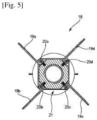
- the 19th tail is instead shown in its deployed position on the Figure 3 as well as on the Figure 5 , which is a cross-section of the sub-caliber 16 projectile at the level of the extension 10 carrying this tail.
- the fins 19a, 19b, 19c and 19d forming the tail 19 are each pivotally mounted, on the extension 10 of the sub-caliber projectile 16, around a hinge, respectively 20a, 20b, 20c and 20d, the axes of which are substantially parallel to the longitudinal axis of the sub-caliber projectile 16.
- the extension 10 of the projectile 9 has in section, at the level of the tail 19, a substantially square external section.
- the hinges, respectively 20a, 20b, 20c and 20d, of the fins 19a, 19b, 19c and 19d, are placed along the edges of this square section, in such a way that each fin 19a, 19b, 19c and 19d can, in its folded position, extend against each of the substantially flat faces 21 with a square section of the extension 10 of the sub-caliber projectile 16.
- the internal shape of the axial bore of the sabot 11 matches, at the level of the tail 19, the shape of the fins in this folded position, as illustrated in Figure 4 which shows segments 11a, 11b, 11c and 11d of sabot 11.
- Sabot 11 when it surrounds the sub-caliber projectile 16, therefore holds fins 19a, 19b, 19c and 19d of the tail 19 in their folded position on the corresponding flat face 21.
- This tail 19 then has a very reduced wingspan, less than the caliber of the weapon tube.
- the fins 19a, 19b, 19c and 19d are no longer held in their folded position. These fins 19a, 19b, 19c and 19d then pivot, around their respective hinges 20a, 20b, 20c and 20d, to their deployed position.
- this pivoting is done under the effect of centrifugal force, as well as under the effect of aerodynamic forces, the pivoting of each fin from its folded position to its deployed position being done in a direction opposite to the direction of rotation of the projectile 9 in the air. It is also possible, in other embodiments, that springs are provided to drive the fins from their folded position to their deployed position.
- the fins 19a, 19b, 19c and 19d preferably extend in a radial direction, relative to the longitudinal axis of the sub-caliber projectile 16.
- the hinges 20a, 20b, 20c and 20d are advantageously equipped with stops preventing the fins 19a, 19b, 19c and 19d from pivoting beyond this radial orientation which corresponds to their deployed position.
- the tail 19 in the deployed position has a large span, greater than the caliber of the weapon barrel. It can then effectively stabilize the sub-caliber projectile 16 which can thus travel a trajectory of great length.
- the sub-caliber projectile of a telescoped ammunition according to the invention can thus be effectively stabilized by the tail while having a large diameter, compared to the caliber of the weapon barrel.
- This feature gives it a load-carrying capacity greater than the sub-caliber projectiles of telescoped ammunition of the prior art.
- the sub-caliber projectile has a diameter of approximately 20 mm, while the diameter of the weapon is 40 mm.
- the solution of the invention therefore allows the carriage of larger charges in a telescoped ammunition projectile. It also allows this charge to be subjected only to rotation at relatively low speed, which reduces the risk of malfunction of the charge linked to the rotation of the projectile.
- this solution of the invention makes it possible to implement relatively low-caliber munitions equipped with a deployable tail, which therefore includes small mechanical elements.
- This implementation is made possible by the fact that the sabot completely envelops the tail, in its folded position. When the pressure in the ammunition builds up, the tail is protected by the sabot, which prevents it from being damaged.
- the deployable tail according to the invention will also be possible to implement the deployable tail according to the invention with a different number of fins by providing the necessary flat surfaces. Thus, it is possible to manufacture such a tail with two or three fins, or with five or even six fins.
- the sabot it is advantageous for the sabot to be divided into a number of segments identical to the number of fins, but it is also possible to provide a different configuration of the sabot. It is thus possible, for example, to assemble a sabot divided into three segments on the sub-caliber 16 projectile which carries four fins. The three segments will then have to be machined so as to form together a sabot whose axial bore will have a shape complementary to the shape of the tail in the folded position.
Landscapes
- Engineering & Computer Science (AREA)
- General Engineering & Computer Science (AREA)
- Physics & Mathematics (AREA)
- Fluid Mechanics (AREA)
- Chemical & Material Sciences (AREA)
- Combustion & Propulsion (AREA)
- Toys (AREA)
- Aiming, Guidance, Guns With A Light Source, Armor, Camouflage, And Targets (AREA)
- Portable Nailing Machines And Staplers (AREA)
Claims (9)
- - Teleskopmunition (1), umfassend eine Hülse (2), in der ein Unterkalibergeschoss (16) mit einem auswerfbaren segmentierten Treibkäfig (11), eine Treibladung (8) und eine Zündvorrichtung (4) für die Treibladung untergebracht sind, dadurch gekennzeichnet, dass das Unterkalibergeschoss (16) eine Verlängerung (10) aufweist, die ein zwischen einer gegen die Verlängerung eingeklappten Position und einer ausgefahrenen Position bewegliches Leitwerk (19) aufweist, wobei der Treibkäfig (11) das Leitwerk (19) in der eingeklappten Position hält, und dass das Leitwerk (19) Flügel (19a, 19b, 19c, 19d) umfasst, die gelenkig relativ zur Verlängerung (10) des Unterkalibergeschosses (16) über Scharniere (20a, 20b, 20c, 20d) mit Achsen parallel zur Längsachse des Unterkalibergeschosses (19) befestigt sind.
- - Munition (1) nach Anspruch 1, dadurch gekennzeichnet, dass der Treibkäfig (11) das Leitwerk (19) umgibt, um es zu isolieren, um den Kontakt zwischen dem Leitwerk (19) und der Treibladung (8) zu verhindern.
- - Munition (1) nach Anspruch 1 oder 2, dadurch gekennzeichnet, dass jeder der Flügel (19a, 19b, 19c, 19d) beweglich ist zwischen: einer eingeklappten Position, in der sich jeder Flügel (19) entlang einer Außenfläche des Unterkalibergeschosses (16) erstreckt, und einer ausgefahrenen Position, in der sich jeder Flügel (19) radial um die Verlängerung (10) des Unterkalibergeschosses (16) herum erstreckt.
- - Munition (1) nach Anspruch 3, dadurch gekennzeichnet, dass die Scharniere (20a, 20b, 20c, 20d) mit Anschlägen versehen sind, die das Schwenken der Flügel (19a, 19b, 19c, 19d) aus einem Winkelbereich zwischen der eingeklappten Position und der ausgefahrenen Position verhindern.
- - Munition (1) nach einem der vorstehenden Ansprüche, dadurch gekennzeichnet, dass das Leitwerk (19) in der ausgefahrenen Position einen Durchmesser aufweist, der größer ist als das Kaliber.
- - Munition (1) nach einem der vorstehenden Ansprüche, dadurch gekennzeichnet, dass die Hülse aus einer im Wesentlichen zylindrischen Hülle (2) besteht, von der ein Ende durch einen Boden (3) verschlossen ist und deren anderes Ende mit einem Führungsring (6) versehen ist, in den das Geschoss (9) eingreift.
- - Munition (1) nach einem der vorstehenden Ansprüche, dadurch gekennzeichnet, dass der Treibkäfig (11) über mindestens einen Teil seiner Länge einen im Wesentlichen zylindrischen Außenquerschnitt aufweist, der dem Kaliber entspricht.
- - Munition (1) nach vorstehendem Anspruch, dadurch gekennzeichnet, dass der Treibkäfig (11) über die gesamte Länge des Unterkalibergeschosses (16) einen im Wesentlichen zylindrischen Außenquerschnitt aufweist, der dem Kaliber entspricht.
- - Munition (1) nach einem der vorstehenden Ansprüche, dadurch gekennzeichnet, dass die Verlängerung (10) des Unterkalibergeschosses (16) ebene Flächen (21) aufweist, die auf die Längsachse des Unterkalibergeschosses ausgerichtet sind, auf denen die Flügel (19) in einer eingeklappten Position umgelegt sind.
Applications Claiming Priority (2)
| Application Number | Priority Date | Filing Date | Title |
|---|---|---|---|
| FR1909698A FR3100323B1 (fr) | 2019-09-03 | 2019-09-03 | Munition télescopée comprenant un projectile sous-calibré stabilisé par un empennage déployable |
| PCT/EP2020/074651 WO2021043928A1 (fr) | 2019-09-03 | 2020-09-03 | Munition télescopée comprenant un projectile sous-calibré stabilisé par un empennage déployable |
Publications (3)
| Publication Number | Publication Date |
|---|---|
| EP4088082A1 EP4088082A1 (de) | 2022-11-16 |
| EP4088082B1 true EP4088082B1 (de) | 2025-07-02 |
| EP4088082C0 EP4088082C0 (de) | 2025-07-02 |
Family
ID=69172905
Family Applications (1)
| Application Number | Title | Priority Date | Filing Date |
|---|---|---|---|
| EP20764672.0A Active EP4088082B1 (de) | 2019-09-03 | 2020-09-03 | Teleskopische munition mit einem durch eine ausfahrbare leitvorrichtung stabilisierten unterkalibrigen geschoss |
Country Status (5)
| Country | Link |
|---|---|
| US (1) | US20220290953A1 (de) |
| EP (1) | EP4088082B1 (de) |
| KR (1) | KR20220056230A (de) |
| FR (1) | FR3100323B1 (de) |
| WO (1) | WO2021043928A1 (de) |
Family Cites Families (23)
| Publication number | Priority date | Publication date | Assignee | Title |
|---|---|---|---|---|
| US3695556A (en) * | 1970-08-03 | 1972-10-03 | Us Navy | Hinged stability and control fin assembly |
| US4197801A (en) * | 1978-04-07 | 1980-04-15 | Ford Aerospace & Communications Corporation | Ammunition round |
| DE3151525C1 (de) * | 1981-12-24 | 1991-10-10 | Rheinmetall Gmbh | Munitionseinheit |
| US4607810A (en) * | 1983-03-07 | 1986-08-26 | Ford Aerospace & Communications Corporation | Passive constraint for aerodynamic surfaces |
| DE3309533A1 (de) * | 1983-03-17 | 1984-09-20 | Diehl GmbH & Co, 8500 Nürnberg | Fluegelstabilisiertes geschoss mit treibkaefig |
| US4667899A (en) * | 1984-11-28 | 1987-05-26 | General Dynamics, Pomona Division | Double swing wing self-erecting missile wing structure |
| US4844380A (en) * | 1985-11-25 | 1989-07-04 | Hughes Aircraft Company | Detachable thrust vector mechanism for an aeronautical vehicle |
| US4778127A (en) * | 1986-09-02 | 1988-10-18 | United Technologies Corporation | Missile fin deployment device |
| DE3737708A1 (de) * | 1987-11-06 | 1989-05-18 | Diehl Gmbh & Co | Treibspiegelgeschoss fuer ein einstecklaufgeraet |
| US4802415A (en) * | 1987-12-28 | 1989-02-07 | Ford Aerospace Corporation | Telescoped ammunition round having subcaliber projectile sabot with integral piston |
| FR2647891B1 (fr) | 1989-06-01 | 1994-05-20 | Etat Francais Delegue Armement | Dispositif de maintien d'un projectile sous-calibre relativement a l'enveloppe d'une munition telescopee |
| FR2679994B1 (fr) * | 1991-07-31 | 1995-02-17 | Giat Ind Sa | Dispositif d'allumage de la charge propulsive d'une munition, notamment telescopee, et munition initiee par un tel dispositif d'allumage. |
| KR0176320B1 (ko) * | 1995-12-09 | 1999-04-01 | 배문한 | 유도탄 날개 전개 및 고정 장치 |
| SE508857C2 (sv) * | 1997-03-25 | 1998-11-09 | Bofors Ab | Fenstabiliserad base-bleedgranat |
| US7952055B2 (en) * | 2007-11-21 | 2011-05-31 | Raytheon Company | Methods and apparatus for deploying control surfaces sequentially |
| KR101234218B1 (ko) * | 2010-06-25 | 2013-02-18 | 국방과학연구소 | 비행체의 날개장치 및 이를 구비하는 비행체 |
| GB201219468D0 (en) * | 2012-10-30 | 2012-12-12 | Alculumbre Michael | Projectile |
| US9593922B2 (en) * | 2013-03-14 | 2017-03-14 | Bae Systems Land & Armaments L.P. | Fin deployment system |
| US9021958B1 (en) * | 2014-01-01 | 2015-05-05 | Michael S. Bradbury | Broadhead-bullet with sabot |
| US9759535B2 (en) * | 2014-04-30 | 2017-09-12 | Bae Systems Land & Armaments L.P. | Gun launched munition with strakes |
| FR3041744B1 (fr) * | 2015-09-29 | 2018-08-17 | Nexter Munitions | Projectile d'artillerie ayant une phase pilotee. |
| US20170307334A1 (en) * | 2016-04-26 | 2017-10-26 | Martin William Greenwood | Apparatus and System to Counter Drones Using a Shoulder-Launched Aerodynamically Guided Missile |
| US11274907B2 (en) * | 2020-04-28 | 2022-03-15 | Raytheon Company | Shroud driven deployable flight surfaces and method |
-
2019
- 2019-09-03 FR FR1909698A patent/FR3100323B1/fr active Active
-
2020
- 2020-09-03 KR KR1020227010988A patent/KR20220056230A/ko not_active Ceased
- 2020-09-03 EP EP20764672.0A patent/EP4088082B1/de active Active
- 2020-09-03 US US17/635,187 patent/US20220290953A1/en not_active Abandoned
- 2020-09-03 WO PCT/EP2020/074651 patent/WO2021043928A1/fr not_active Ceased
Also Published As
| Publication number | Publication date |
|---|---|
| US20220290953A1 (en) | 2022-09-15 |
| EP4088082A1 (de) | 2022-11-16 |
| FR3100323B1 (fr) | 2022-07-22 |
| EP4088082C0 (de) | 2025-07-02 |
| FR3100323A1 (fr) | 2021-03-05 |
| WO2021043928A1 (fr) | 2021-03-11 |
| KR20220056230A (ko) | 2022-05-04 |
Similar Documents
| Publication | Publication Date | Title |
|---|---|---|
| EP0905473B1 (de) | Grosskalibriges und weitreichendes Artilleriegeschoss | |
| EP0346214B1 (de) | Verfahren und Vorrichtung zum Auswerfen von Submunition | |
| EP2923171B1 (de) | Rotationsstabilisiertes geschoss mit ausstoss einer nutzlast | |
| CH634142A5 (fr) | Mecanisme de lancement d'un projectile sous-calibre. | |
| EP1045221B1 (de) | Bremsvorrichtung für die Flugbahngeschwindigkeit eines Geschosses | |
| FR2726357A1 (fr) | Balle de chasse a fleche telescopee, comportant un sous-projectile associe a un lanceur | |
| EP4088082B1 (de) | Teleskopische munition mit einem durch eine ausfahrbare leitvorrichtung stabilisierten unterkalibrigen geschoss | |
| EP3994421B1 (de) | Teleskopmunition mit einem projektil mit einem stapel gerillter scheiben | |
| EP2578987B1 (de) | Drallstabilisiertes Geschoss | |
| EP0728293B1 (de) | Flintenlaufgeschoss mit doppeleindringung und reduzierter schussweite | |
| FR2960055A1 (fr) | Munition guidee protegee par une coiffe aerodynamique | |
| EP1701131B1 (de) | Panzergeschoss | |
| EP4008992B1 (de) | Drallstabilisiertes geschoss | |
| EP0401114B1 (de) | Vorrichtung zum Halten eines Geschosses in bezug auf das Gehäuse einer teleskopartigen Munition | |
| FR2606869A1 (fr) | Ceinture derapante pour projectile de tout calibre | |
| EP1693646B1 (de) | Führungsband für Artilleriegeschoss | |
| EP0338879B1 (de) | Stabilisierungsvorrichtung für Geschosse von gezogenen Läufen | |
| EP4589243A1 (de) | Leitwerkstabilisiertes artilleriegeschoss mit einer leitwerkschutzverkleidung, die durch entnahme von treibladungsgasen abgeworfen werden kann | |
| EP2913628A1 (de) | Geschosszünder eines Artillerieprojektils, der eine in Flugrichtung wirkende Bremsvorrichtung umfasst | |
| FR3110687A1 (fr) | Projectile sous calibré et procédé de neutralisation d'un objectif en mettant en oeuvre un tel projectile. | |
| FR2612621A1 (fr) | Ceinture derapante a spires pour projectiles de tout calibre | |
| FR2834556A1 (fr) | Projectile destine au maintien de l'ordre, compose de deux hemi-projectiles identiques relies entre eux et se deployant a la sortie du canon pour tourner a la facon d'une helice d'avion |
Legal Events
| Date | Code | Title | Description |
|---|---|---|---|
| STAA | Information on the status of an ep patent application or granted ep patent |
Free format text: STATUS: UNKNOWN |
|
| STAA | Information on the status of an ep patent application or granted ep patent |
Free format text: STATUS: THE INTERNATIONAL PUBLICATION HAS BEEN MADE |
|
| PUAI | Public reference made under article 153(3) epc to a published international application that has entered the european phase |
Free format text: ORIGINAL CODE: 0009012 |
|
| STAA | Information on the status of an ep patent application or granted ep patent |
Free format text: STATUS: REQUEST FOR EXAMINATION WAS MADE |
|
| 17P | Request for examination filed |
Effective date: 20220509 |
|
| AK | Designated contracting states |
Kind code of ref document: A1 Designated state(s): AL AT BE BG CH CY CZ DE DK EE ES FI FR GB GR HR HU IE IS IT LI LT LU LV MC MK MT NL NO PL PT RO RS SE SI SK SM TR |
|
| DAV | Request for validation of the european patent (deleted) | ||
| DAX | Request for extension of the european patent (deleted) | ||
| GRAP | Despatch of communication of intention to grant a patent |
Free format text: ORIGINAL CODE: EPIDOSNIGR1 |
|
| STAA | Information on the status of an ep patent application or granted ep patent |
Free format text: STATUS: GRANT OF PATENT IS INTENDED |
|
| INTG | Intention to grant announced |
Effective date: 20250128 |
|
| GRAS | Grant fee paid |
Free format text: ORIGINAL CODE: EPIDOSNIGR3 |
|
| GRAA | (expected) grant |
Free format text: ORIGINAL CODE: 0009210 |
|
| STAA | Information on the status of an ep patent application or granted ep patent |
Free format text: STATUS: THE PATENT HAS BEEN GRANTED |
|
| AK | Designated contracting states |
Kind code of ref document: B1 Designated state(s): AL AT BE BG CH CY CZ DE DK EE ES FI FR GB GR HR HU IE IS IT LI LT LU LV MC MK MT NL NO PL PT RO RS SE SI SK SM TR |
|
| REG | Reference to a national code |
Ref country code: GB Ref legal event code: FG4D Free format text: NOT ENGLISH |
|
| REG | Reference to a national code |
Ref country code: CH Ref legal event code: EP |
|
| REG | Reference to a national code |
Ref country code: DE Ref legal event code: R096 Ref document number: 602020053840 Country of ref document: DE |
|
| REG | Reference to a national code |
Ref country code: IE Ref legal event code: FG4D Free format text: LANGUAGE OF EP DOCUMENT: FRENCH |
|
| U01 | Request for unitary effect filed |
Effective date: 20250730 |
|
| U07 | Unitary effect registered |
Designated state(s): AT BE BG DE DK EE FI FR IT LT LU LV MT NL PT RO SE SI Effective date: 20250808 |
|
| U20 | Renewal fee for the european patent with unitary effect paid |
Year of fee payment: 6 Effective date: 20251107 |
|
| PG25 | Lapsed in a contracting state [announced via postgrant information from national office to epo] |
Ref country code: IS Free format text: LAPSE BECAUSE OF FAILURE TO SUBMIT A TRANSLATION OF THE DESCRIPTION OR TO PAY THE FEE WITHIN THE PRESCRIBED TIME-LIMIT Effective date: 20251102 |
|
| PG25 | Lapsed in a contracting state [announced via postgrant information from national office to epo] |
Ref country code: NO Free format text: LAPSE BECAUSE OF FAILURE TO SUBMIT A TRANSLATION OF THE DESCRIPTION OR TO PAY THE FEE WITHIN THE PRESCRIBED TIME-LIMIT Effective date: 20251002 |
|
| PG25 | Lapsed in a contracting state [announced via postgrant information from national office to epo] |
Ref country code: HR Free format text: LAPSE BECAUSE OF FAILURE TO SUBMIT A TRANSLATION OF THE DESCRIPTION OR TO PAY THE FEE WITHIN THE PRESCRIBED TIME-LIMIT Effective date: 20250702 |
|
| PG25 | Lapsed in a contracting state [announced via postgrant information from national office to epo] |
Ref country code: GR Free format text: LAPSE BECAUSE OF FAILURE TO SUBMIT A TRANSLATION OF THE DESCRIPTION OR TO PAY THE FEE WITHIN THE PRESCRIBED TIME-LIMIT Effective date: 20251003 |
|
| PG25 | Lapsed in a contracting state [announced via postgrant information from national office to epo] |
Ref country code: CZ Free format text: LAPSE BECAUSE OF FAILURE TO SUBMIT A TRANSLATION OF THE DESCRIPTION OR TO PAY THE FEE WITHIN THE PRESCRIBED TIME-LIMIT Effective date: 20250702 |
|
| PG25 | Lapsed in a contracting state [announced via postgrant information from national office to epo] |
Ref country code: PL Free format text: LAPSE BECAUSE OF FAILURE TO SUBMIT A TRANSLATION OF THE DESCRIPTION OR TO PAY THE FEE WITHIN THE PRESCRIBED TIME-LIMIT Effective date: 20250702 |
|
| PG25 | Lapsed in a contracting state [announced via postgrant information from national office to epo] |
Ref country code: RS Free format text: LAPSE BECAUSE OF FAILURE TO SUBMIT A TRANSLATION OF THE DESCRIPTION OR TO PAY THE FEE WITHIN THE PRESCRIBED TIME-LIMIT Effective date: 20251002 |
|
| PG25 | Lapsed in a contracting state [announced via postgrant information from national office to epo] |
Ref country code: ES Free format text: LAPSE BECAUSE OF FAILURE TO SUBMIT A TRANSLATION OF THE DESCRIPTION OR TO PAY THE FEE WITHIN THE PRESCRIBED TIME-LIMIT Effective date: 20250702 |
|
| PG25 | Lapsed in a contracting state [announced via postgrant information from national office to epo] |
Ref country code: SM Free format text: LAPSE BECAUSE OF FAILURE TO SUBMIT A TRANSLATION OF THE DESCRIPTION OR TO PAY THE FEE WITHIN THE PRESCRIBED TIME-LIMIT Effective date: 20250702 |
|
| PG25 | Lapsed in a contracting state [announced via postgrant information from national office to epo] |
Ref country code: SK Free format text: LAPSE BECAUSE OF FAILURE TO SUBMIT A TRANSLATION OF THE DESCRIPTION OR TO PAY THE FEE WITHIN THE PRESCRIBED TIME-LIMIT Effective date: 20250702 |