EP4088583B1 - Transporteur de produits et dispositif de transport - Google Patents
Transporteur de produits et dispositif de transport Download PDFInfo
- Publication number
- EP4088583B1 EP4088583B1 EP21173309.2A EP21173309A EP4088583B1 EP 4088583 B1 EP4088583 B1 EP 4088583B1 EP 21173309 A EP21173309 A EP 21173309A EP 4088583 B1 EP4088583 B1 EP 4088583B1
- Authority
- EP
- European Patent Office
- Prior art keywords
- product carrier
- edge strips
- wide
- longitudinal
- guide
- Prior art date
- Legal status (The legal status is an assumption and is not a legal conclusion. Google has not performed a legal analysis and makes no representation as to the accuracy of the status listed.)
- Active
Links
Images



Classifications
-
- A—HUMAN NECESSITIES
- A23—FOODS OR FOODSTUFFS; TREATMENT THEREOF, NOT COVERED BY OTHER CLASSES
- A23G—COCOA; COCOA PRODUCTS, e.g. CHOCOLATE; SUBSTITUTES FOR COCOA OR COCOA PRODUCTS; CONFECTIONERY; CHEWING GUM; ICE-CREAM; PREPARATION THEREOF
- A23G1/00—Cocoa; Cocoa products, e.g. chocolate; Substitutes therefor
- A23G1/04—Apparatus specially adapted for manufacture or treatment of cocoa or cocoa products
- A23G1/20—Apparatus for moulding, cutting or dispensing chocolate
- A23G1/26—Conveying devices for chocolate moulds
-
- A—HUMAN NECESSITIES
- A23—FOODS OR FOODSTUFFS; TREATMENT THEREOF, NOT COVERED BY OTHER CLASSES
- A23G—COCOA; COCOA PRODUCTS, e.g. CHOCOLATE; SUBSTITUTES FOR COCOA OR COCOA PRODUCTS; CONFECTIONERY; CHEWING GUM; ICE-CREAM; PREPARATION THEREOF
- A23G3/00—Sweetmeats; Confectionery; Marzipan; Coated or filled products
- A23G3/02—Apparatus specially adapted for manufacture or treatment of sweetmeats or confectionery; Accessories therefor
- A23G3/0236—Shaping of liquid, paste, powder; Manufacture of moulded articles, e.g. modelling, moulding, calendering
- A23G3/0252—Apparatus in which the material is shaped at least partially in a mould, in the hollows of a surface, a drum, an endless band, or by a drop-by-drop casting or dispensing of the material on a surface, e.g. injection moulding, transfer moulding
- A23G3/0278—Mould conveyor, e.g. with the associated mould
-
- A—HUMAN NECESSITIES
- A23—FOODS OR FOODSTUFFS; TREATMENT THEREOF, NOT COVERED BY OTHER CLASSES
- A23G—COCOA; COCOA PRODUCTS, e.g. CHOCOLATE; SUBSTITUTES FOR COCOA OR COCOA PRODUCTS; CONFECTIONERY; CHEWING GUM; ICE-CREAM; PREPARATION THEREOF
- A23G7/00—Other apparatus or process specially adapted for the chocolate or confectionery industry
- A23G7/0025—Apparatus for stacking or unstacking, e.g. stacking of chocolate, confectionery, moulds, trays, except stacking of sticks
-
- B—PERFORMING OPERATIONS; TRANSPORTING
- B65—CONVEYING; PACKING; STORING; HANDLING THIN OR FILAMENTARY MATERIAL
- B65G—TRANSPORT OR STORAGE DEVICES, e.g. CONVEYORS FOR LOADING OR TIPPING, SHOP CONVEYOR SYSTEMS OR PNEUMATIC TUBE CONVEYORS
- B65G61/00—Use of pick-up or transfer devices or of manipulators for stacking or de-stacking articles not otherwise provided for
-
- B—PERFORMING OPERATIONS; TRANSPORTING
- B65—CONVEYING; PACKING; STORING; HANDLING THIN OR FILAMENTARY MATERIAL
- B65G—TRANSPORT OR STORAGE DEVICES, e.g. CONVEYORS FOR LOADING OR TIPPING, SHOP CONVEYOR SYSTEMS OR PNEUMATIC TUBE CONVEYORS
- B65G2201/00—Indexing codes relating to handling devices, e.g. conveyors, characterised by the type of product or load being conveyed or handled
- B65G2201/02—Articles
- B65G2201/0202—Agricultural and processed food products
Definitions
- the product carriers can be transported along a food production line, for example, using two parallel chains.
- Such chains can be equipped with protruding flights that come into contact with the product carriers to pull or push the product carriers along the line.
- the transport speed can vary within the processing stations, which can be designed as modules, for example. When a product carrier is picked up or dropped off at a processing station, it may be necessary to adjust the transport speed.
- the system can include buffer zones for this purpose.
- a chocolate manufacturing machine in which a plurality of chocolate shells are conveyed along a transport path from a chocolate dispenser to a chocolate cooler by means of a walking beam conveyor.
- the chocolate shell has a rectangular base and a pair of opposite side walls extending therefrom.
- the walking beam conveyor has a plurality of conveying projections, and the side walls of the chocolate shell have conveying recesses for receiving the conveying projections. In this way, the walking beam conveyor can securely engage the chocolate shell to move it downstream.
- the product carriers are stackable and the greatest possible stability of the stack is ensured.
- the product carrier can have stepped recesses into which the product carrier's feet engage. Dirt can collect in these stepped recesses.
- the object of the above invention is to avoid the disadvantages of the known and to provide a product carrier and a transport device by means of which a variable and at the same time precise transport of the product carriers is made possible.
- a product carrier according to the invention is suitable for transporting food products, in particular chocolate products, in a transport device, in particular in a plant for producing food products.
- the product carrier has a top side for placing and/or inserting products and a bottom side opposite the top side.
- the product carrier has a rectangular basic shape with long sides that have a length in a longitudinal direction and wide sides that have a width perpendicular to the longitudinal direction.
- the length can be smaller than the width.
- the long sides extend in the lengthwise direction, the wide sides in a widthwise direction perpendicular to this.
- the product carrier has opposing longitudinal edge strips on the long sides, each of which has a drive recess.
- the longitudinal edge strips preferably form a right angle with the top side.
- the drive recesses of the two longitudinal edge strips are open in a direction away from the top.
- the drive recesses each have a longitudinal extension of greater than 50%, preferably greater than 80%, of the length of the product carrier. Therefore, exactly one drive recess is provided on each longitudinal edge strip.
- the drive recesses have stop edges in and against the transport direction.
- the drive recesses are preferably designed such that the edge of the drive recess forms an angle of between 85° and 95° with the lower edge of the longitudinal edge strip.
- a driver of a drive chain or a push bar arrangement can engage in the drive recesses and pull the product carrier along.
- the drivers can rest against the stop edges without slipping.
- the product carrier Since the product carrier has stop edges in and against the transport direction, it does not matter in which direction the product carrier is placed on the transport system or inserted into the transport system.
- the longitudinal extension of the drive recesses allows for flexibility in transport speed. This allows a carrier to be moved within the drive recess without moving the product carrier. For example, the distance to other product carriers that are already being moved by carriers moving parallel and simultaneously can be adjusted.
- the drive recesses of the two longitudinal edge strips are located opposite each other.
- the drive recesses are preferably of equal length and preferably of equal height.
- the length points in the longitudinal direction, and the height points in a direction perpendicular to the longitudinal direction and perpendicular to the width direction.
- the drive recesses of the two longitudinal edge strips are formed symmetrically with respect to a center plane of the product carrier in the longitudinal direction, which runs perpendicular to the orientation of the rectangular basic shape of the product carrier and has a normal in the width direction.
- Product carriers designed in this way are suitable for being pulled along by carriers located exactly opposite one another in the direction of transport.
- the product carrier also features opposing wide edge strips on its wide sides. These wide edge strips preferably form a right angle with the top surface.
- the wide edge strips each have at least one guide recess.
- the guide recesses of the wide edge strips are open in the direction away from the top side. They have a longitudinal extension of less than 10%, preferably less than 5%, of the width of the product carrier.
- the guide recesses of the two wide edge strips are opposite each other.
- Opposite guide recesses are preferably of equal length and preferably of equal height.
- the longitudinal extent of the guide recesses is in the direction of the width of the product carrier, and the height is in a direction perpendicular to the longitudinal direction and perpendicular to the width direction.
- all guide recesses have the same longitudinal extent and height.
- the guide recesses of the two wide edge strips are formed symmetrically with respect to a center plane of the product carrier, which is perpendicular to the orientation of the rectangular basic shape of the product carrier and perpendicular to the longitudinal direction.
- a web guide of a transport system which runs along the transport direction, can engage in the guide recesses so that the product carrier is supported from the underside.
- Each of the wide edge strips can have one to eight guide recesses, for up to eight web guides.
- the product carrier can preferably rest on more than one web guide and has more than one guide recess.
- the product carrier has longitudinal and wide edge strips. These stabilize the product carrier, especially if it is made of plastic. At the same time, the recesses The edge strips provide access points for a drive and a guide.
- At least one separating rib can be arranged on the underside of the product carrier, which extends in the width direction and perpendicular to the longitudinal direction.
- the separating rib forms at least two channels which are open in a direction away from the top side and along which air can be directed.
- the separating rib has a lower height than the height of the longitudinal edge strips and/or the wide edge strips.
- the separating rib stabilizes the product carrier. Air can be guided along the product carrier through the channels. Depending on the orientation of the separating rib, the channels, like the separating rib, also run in the width direction, i.e., perpendicular to the length direction. Therefore, during transport, tempering air, such as cooling air, can be blown onto the product carrier from the side. This air flows through the channels along the entire product carrier, thereby tempering the transported product.
- tempering air such as cooling air
- the separating rib can have a material thickness of 1 mm to 4 mm and acts as a baffle for the airflow.
- the separating rib can have a material thickness that is greater or lesser than the material thickness of the product carrier in the area of the longitudinal edge strips and/or the wide edge strips.
- a plurality of, in particular uniformly spaced, separating ribs are provided, which form a plurality of channels.
- the separating rib may have a smaller longitudinal extension than the width of the product carrier.
- the separating rib can be arranged between the wide edge strips.
- the height of the separating rib is preferably less than or equal to the height of the wide edge strips at the guide recesses.
- the separating rib is therefore not in the way when a web guide running in the transport direction engages the guide recesses.
- the product carrier then rests preferably on the web guide in the area of the wide edge strips.
- Reinforcing ribs extending in the longitudinal direction and, in particular, having a lower height than the separating rib can be provided in the channels.
- a plurality of reinforcing ribs arranged parallel to one another and more preferably evenly spaced apart are provided in each channel.
- Reinforcing ribs are arranged in particular between separating ribs and run in particular perpendicular to the separating ribs.
- the reinforcing ribs in particular, provide further stabilization of the product carrier.
- the reinforcing ribs do not impede airflow through the channels, but rather create turbulence that promotes heat exchange between the air and the product carrier.
- the longitudinal edge strips and/or the wide edge strips are bevelled towards the top side of the product carrier, preferably along the entire length and/or width of the product carrier.
- the beveled area of the wide edge strips preferably forms an angle of between 30° and 60° with the longitudinal direction of the product carrier.
- the beveled area of the longitudinal edge strips preferably forms an angle of between 30° and 60° with the width direction of the product carrier.
- the bevel is formed circumferentially around the surface of the product carrier.
- Stacks of product carriers are formed, for example, when the product carriers are stored and ready for use or when the product carriers are refrigerated with filled alveoli.
- the longitudinal edge strips, the wide edge strips, the drive recesses and the separating ribs are designed in such a way that cooling air can be guided along the channels even when stacked.
- the product carrier may comprise support strips, each of which is arranged parallel to the wide-edge strips and which may have the same maximum height as the wide-edge strips.
- the support strips may have recesses that are aligned with the guide recesses of the wide-edge strips.
- the support strips Preferably, the support strips have the same number of recesses as the wide-edge strips.
- the recesses are, in particular, symmetrical. to the guide recesses formed with respect to a plane which is perpendicular to the orientation of the rectangular basic shape of the product carrier and perpendicular to the longitudinal direction.
- One or more alveoli can be arranged on the top side of the product carrier.
- the alveoli are preferably recessed into the top surface.
- the top surface can have depressions that form the alveoli.
- the part of the guide recess contour that abuts the edge of the wide edge strips facing away from the top can form an angle of 85°-95° with the edge of the wide edge strips facing away from the top.
- the guide recess is thus steep enough at the edge to ensure that a web guide has a lateral stop and cannot slip off.
- the object is also achieved by a transport device, in particular in a plant for the production of food products, with at least one product carrier as described above.
- the transport device advantageously comprises at least one movable driver, which is designed to rest against one of the stop edges of the product carrier in order to pull the product carrier along.
- the transport device comprises pairs of drivers opposite each other in the transport direction, each of which is inserted into opposite drive recesses. of a product carrier.
- the transport device can have sections with fewer and sections with more parallel web guides, depending on how much support a product carrier requires in the respective section.
- the product carrier has at least as many guide recesses in the respective wide edge strips as the maximum number of parallel web guides in a transport system.
- the carrier can be arranged on a transport chain or on a push bar arrangement.
- the transport device can be designed to transport the product carrier from one processing station to the next or within a processing station.
- the processing device can be a mold heater, a cooling station, a pouring station, a sleeve forming station, a cold stamping station, an opening forming station, a filling station, an insertion station, a vibrating station, a lidding station, a licking station, a decorating station, a demolding station, a stacking and/or unstacking station, a spraying station, a printing station, an inserting station, a packaging station, a film application station and/or a control station.
- the transport device can comprise a robot arrangement with at least one gripper.
- the gripper can engage in the guide recesses of the product carrier.
- the gripper can comprise a gripping bar on which pins are arranged that engage in the guide recesses of the product carrier.
- the gripper preferably has a number of pins that corresponds to the number of guide recesses in a wide-edged bar.
- a marking for identifying the product carrier can be applied to the longitudinal edge strip and/or the wide edge strip.
- a code in particular a barcode, can be printed, etched, or engraved.
- the transport device preferably comprises a reader for recognizing the marking.
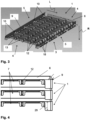
- Figure 1 shows a product carrier 1 according to the invention in a first perspective view
- Figure 2 the product carrier 1 in a second perspective view
- Figure 3 the product carrier 1 according to the invention in a third perspective view.
- FIG 1 the top side 2 of the product carrier 1 is shown, on which a plurality of alveoli 22 for inserting or filling products is arranged.
- the Figures 2 and 3 show the underside 3 of the product carrier 1 opposite the top side 2.
- the product carrier 1 has a rectangular basic shape with long sides 4 which have a length l in a longitudinal direction L, wherein the longitudinal direction corresponds to the typical transport direction T.
- the product carrier 1 has wide sides 5 which have a width b in a width direction B perpendicular to the longitudinal direction L.
- the drive recesses 7 of the two longitudinal edge strips 6 are open in a direction R pointing away from the upper side 2 and have a longitudinal extension 8 of greater than 80% of the length l of the product carrier 1. In and against the longitudinal direction L, the drive recesses 7 have stop edges 25, on which drivers 101 (see Figure 9 ) and pull or push the product carrier 1.
- opposing wide edge strips 9 are provided (see Figure 3 ), each having five guide recesses 10 which are open in the direction R pointing away from the upper side 2.
- separating ribs 12 are arranged, which extend perpendicular to the longitudinal direction L.
- the separating ribs 12 separate channels 13 from each other, which are open in the direction R pointing away from the upper side 2.
- Reinforcing ribs 18 are mounted within the channels 13 and extend in the longitudinal direction L. These stabilize the product carrier 1.
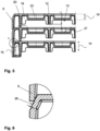
- Figure 4 shows a stack of product carriers 1 in a side view.
- the longitudinal edge strips 6 and the wide edge strips 9 are beveled toward the top side 2 of the product carriers 1.
- the longitudinal edge strips 6 and the wide edge strips 9 are beveled along the entire length l and width b.
- the drive recesses 7 have a clear height 29 which is large enough to allow cooling air to flow through the channels 13 even when the product carriers 1 are stacked.
- Figure 5 shows a stack of product carriers in a cross-sectional view
- Figure 6 a detail from Figure 5 .
- Support strips 20 are arranged parallel to the wide edge strips 9 and reinforce the product carrier 1 in the edge area.
- the separating ribs 12 have a lower height 14 than the maximum height 15 of the longitudinal edge strips 6 and the wide edge strips 9. However, the height 14 of the separating ribs 12 is greater than the depth 27 of the alveoli 22. Therefore, the channels 13 are formed between the separating ribs 12 in such a way that cooling air can flow along the underside of the alveoli 22.
- the wide edge strip 9 of an upper product carrier 1 rests on the beveled area 26 of the product carrier 1 located below.
- the product carrier 1 thus sits firmly in the stack.
- the beveled area 26 is concave and therefore easy to clean.
- the support ribs 18 mostly have a height 19 which is smaller than the height 14 of the separating ribs 12, so they do not block the channels 13.
- the support ribs 18 have the same height 14 as the separating ribs 12 to ensure a solid connection.
- Figure 7 shows the product carrier 1 according to the invention in a fourth perspective view of the underside and Figure 8 a detail from Figure 7 .
- the separating ribs 12 have a smaller longitudinal extension 16 in the width direction B than the width b of the product carrier 1 (see Figure 1 ).
- the separating ribs not into the drive recess 7 and do not obstruct the space that the drivers (see Figure 9 ) need.
- the support strips 20 arranged parallel to the wide edge strips 9 have recesses 28 which are aligned with the guide recess 10 in the wide edge strips 9 in the longitudinal direction L.
- the height 14 of the separating ribs 12 (see Figure 5 ) is also smaller than the height 17 of the wide edge strips 9 at the guide recesses 10. The separating ribs therefore do not extend into the area spanned by the recesses 28 and the guide recesses 10.
- the recesses 28 and the guide recesses 10 thus provide a support surface for a web guide 102 (see Figure 9 ).
- the recesses 28 and the guide recesses 10 have a width extension 11 of less than 10% of the width b of the product carrier 1 (see Figure 1 ).
- the bridge guide 102 (see Figure 9 ) therefore has a firm hold in the guide recess 10 and the product carrier 1 cannot slip sideways.
- Figure 9 shows a sectional view of a transport device 100 according to the invention.
- product carriers 1 are transported in the transport direction T, which here runs perpendicular to the plane of the illustration.
- the transport device 100 comprises movable carriers 101, which are opposite to the transport direction and pull the product carrier 1 along.
- the carriers 101 are arranged on a push bar arrangement 103.
- the push bar arrangement 103 has a drive 104, which moves the carriers 101 in the transport direction, then moves them vertically away from a transport plane 105 in which the surface of the product carrier 1 is located, then moves them counter to the transport direction, and then moves them vertically toward the transport plane 105.
- the carriers 101 can then grip the next product carrier 1, which is pulled along during the next forward movement of the carriers 1.
- the transport device 100 comprises five web guides 102, each of which engages in the guide recesses 10 of the product carriers 1.
- the product carriers 1 thus receive support on the underside 3 when they receive pressure on the upper side 2, for example, from a licking roller 105.
- Figure 10 shows a gripper 201 of a robot arrangement 200 with a stack of product carriers 1 in a sectional view.
- the gripper 201 comprises a drive unit 202, with which the distance between the gripper jaws 203 can be changed.
- the uppermost product carrier 1, which is to be lifted from the stack, for example, can be clamped between the gripper jaws 203.
- the gripper 201 can pick up several product carriers 1, namely up to ten product carriers 1, simultaneously. For this purpose, it has four bolts 204 on each level 203, with two bolts on each opposite sides of the product carrier 1 in order to accommodate the product carriers 1 individually. The bolts 204 are moved from the long side 4 under the product carriers 1.
- FIG 11 shows a second example of a robot arrangement 200.
- the robot arrangement 200 comprises a gripper 201 with which a plurality of stacked product carriers 1 can be fixed and transported.
- the product carriers 1 can have a width extension 11 (see Figure 7) of 272mm to 1500mm and a length extension 8 (see Figure 2 ) from 275mm to 460mm.
- the product carriers 1 may contain or be made of plastic, in particular polycarbonate, or metal.
- the product carriers 1 can contain 5 to 300 alveoli 22 (see Figure 5 ) include.
Landscapes
- Life Sciences & Earth Sciences (AREA)
- Chemical & Material Sciences (AREA)
- Engineering & Computer Science (AREA)
- Food Science & Technology (AREA)
- Polymers & Plastics (AREA)
- Packages (AREA)
- Confectionery (AREA)
- Belt Conveyors (AREA)
- Feeding Of Articles By Means Other Than Belts Or Rollers (AREA)
Claims (15)
- Support de produit (1) destiné au transport de produits alimentaires, en particulier de produits à base de chocolat, dans un dispositif de transport (100), notamment dans une système de production de produits alimentaires,le support de produit (1) présentant une face supérieure (2) destinée à recevoir et/ou à insérer des produits et une face inférieure (3) opposée à la face supérieure (2),le support de produit (1) ayant une forme de base rectangulaire avec des côtés longitudinaux (4) de longueur (l) dans une direction longitudinale (L), et des côtés transversaux (5) de largeur (b) dans une direction transversale (B) perpendiculaire à la direction longitudinale (L),caractérisé en ce quesur les côtés longitudinaux (4),le support de produit (1) comporte des bandes de bord longitudinales (6) opposées l'une à l'autre et qui comporte chacune un évidement d'entraînement (7)les évidements d'entraînement (7) des deux bandes de bord longitudinales (6) étant ouverts dans une direction (R) orientée à l'opposé de la face supérieure (2), ayant une extension longitudinale (8) supérieure à 50%, de préférence supérieure à 80%, de la longueur (l) du support de produit (1) et comportant des arêtes de butée (25) dans la même direction que ainsi qu'en sens inverse de la direction longitudinale (L),et sur les côtés transversaux (5), le support de produit (1) comporte des bandes de bord transversal (9) opposées les unes aux autres et comportant chacune au moins un évidement de guidage (10), les évidements de guidage (10) des bandes de bord transversal (9) étant ouverts dans une direction (R) orientée à l'opposé de la face supérieure (2), de telle sorte qu'un guide en forme de nervures d'un système de transport, s'étendant selon la direction de transport, puisse s'engager dans les évidements de guidage (10), de sorte que le support de produit soit maintenue depuis la face inférieur, et les évidements de guidage (10) ayant une extension en largeur (11) inférieure à 10%, de préférence inférieure à 5%, de la largeur (b) du support de produit (1).
- Support de produit (1) selon la revendication 1, dans lequelau moins une nervure de séparation est agencée sur la face inférieure (3) du support de produit (1), laquelle s'étend perpendiculairement à la direction longitudinale (L), et forme au moins deux canaux (13) ouverts dans une direction (R) orientée à l'opposé de la face supérieure (2), et le long desquels l'air peut être dirigé,les nervures de séparation (12) présentant en particulier une hauteur (14) inférieure à la hauteur (15) des bandes de bord longitudinales (6) et/ou des bandes de bord transversal (9).
- Support de produit (1) selon la revendication 2, dans lequella nervure de séparation (12) présente une extension longitudinale (16) inférieure à la largeur (B) du support de produit (1)
et/oula hauteur (14) de la nervure de séparation (12) est inférieure ou égale à la hauteur (15) des bandes de bord transversal (9) au niveau des évidements de guidage (10). - Support de produit (1) selon la revendication 2 ou 3, dans lequel des nervures de renforcement (18) sont disposées dans les canaux (13), s'étendant dans la direction longitudinale (L) et présentant notamment une hauteur (19) inférieure à celle de la nervure de séparation (12)
- Support de produit (1) selon l'une quelconque des revendications précédentes, dans lequel les bandes de bord longitudinales (6) et/ou les bandes de bord transversal (9) sont chanfreinées en direction de la face supérieure (2) du support de produit (1), de préférence sur toute la longueur (L) et/ou la largeur (B).
- Support de produit (1) selon l'une quelconque des revendications précédentes, dans lequel le support de produit comprend des bandes de support (20) disposées parallèlement chacune aux bandes de bord transversal (9), et compoortant de préférence autant d'évidements (21) que lesdits bande de bord transversal (9).
- Support de produit (1) selon l'une quelconque des revendications précédentes, dans lequel une ou une pluralité d'alvéoles (22) sont disposées sur la face supérieure (2) du support de produit.
- Support de produit (1) selon l'une quelconque des revendications précédentes,
dans lequel la longueur (L) est inférieure à la largeur (B). - Support de produit (1) selon l'une quelconque des revendications précédentes,
chacune des bandes de bord transversal (9) comporte un à huit évidements de guidage (10). - Support de produit (1) selon l'une quelconque des revendications précédentes,
dans lequel la portion (24) du contour de l'évidement de guidage (10) en contact avec le bord (23) des bandes de bord transversal (9) orienté à l'opposé de la face supérieure (2) et ledit bord (23), forment un angle α comprise entre 85 -95°. - Dispositif de transport (100), notamment dans une système de production de produits alimentaires, comprenant au moins un support de produit (1) selon l'une quelconque des revendications 1 à 10, caractérisé en ce qu'il est configuré de sorte que le support de produit (1) soit transporté dans le système de transport principalement dans une direction correspondant à la direction longitudinale.
- Dispositif de transport (100) selon la revendication 11, comprenant au moins un poussoir mobile (101) adapté pour venir en appui contre l'un des arrêtes de butée (25) du support de produit (1) afin d'entraîner le support de produit (1).
- Dispositif de transport (100) selon la revendication 11 ou 12, comprenant au moins une section de voie comportant au moins un guide en forme de nervure (102), de préférence trois à huit guides (102), lesquels s'engagent dans l'évidement de guidage (10).
- Dispositif de transport (100) selon l'une quelconque des revendications 12 ou 13, dans lequel le poussoir (101) est disposé sur un agencement à barre de poussée (103).
- Dispositif de transport (100) selon l'une quelconque des revendications 11 à 14, comprenant un ensemble robotique (200) avec un préhenseur (201) s'engageant dans les évidements de guidage (10) du support de produit (1).
Priority Applications (5)
| Application Number | Priority Date | Filing Date | Title |
|---|---|---|---|
| EP21173309.2A EP4088583B1 (fr) | 2021-05-11 | 2021-05-11 | Transporteur de produits et dispositif de transport |
| DK21173309.2T DK4088583T3 (da) | 2021-05-11 | 2021-05-11 | Produktbærer og transportindretning |
| PCT/EP2022/025220 WO2022238012A1 (fr) | 2021-05-11 | 2022-05-11 | Support de produit et appareil de transport |
| JP2023568068A JP2024518928A (ja) | 2021-05-11 | 2022-05-11 | 製品キャリア及び搬送装置 |
| US18/559,726 US20240225033A1 (en) | 2021-05-11 | 2022-05-11 | Product carrier and transport device |
Applications Claiming Priority (1)
| Application Number | Priority Date | Filing Date | Title |
|---|---|---|---|
| EP21173309.2A EP4088583B1 (fr) | 2021-05-11 | 2021-05-11 | Transporteur de produits et dispositif de transport |
Publications (2)
| Publication Number | Publication Date |
|---|---|
| EP4088583A1 EP4088583A1 (fr) | 2022-11-16 |
| EP4088583B1 true EP4088583B1 (fr) | 2025-07-02 |
Family
ID=75914248
Family Applications (1)
| Application Number | Title | Priority Date | Filing Date |
|---|---|---|---|
| EP21173309.2A Active EP4088583B1 (fr) | 2021-05-11 | 2021-05-11 | Transporteur de produits et dispositif de transport |
Country Status (5)
| Country | Link |
|---|---|
| US (1) | US20240225033A1 (fr) |
| EP (1) | EP4088583B1 (fr) |
| JP (1) | JP2024518928A (fr) |
| DK (1) | DK4088583T3 (fr) |
| WO (1) | WO2022238012A1 (fr) |
Family Cites Families (8)
| Publication number | Priority date | Publication date | Assignee | Title |
|---|---|---|---|---|
| US2938621A (en) * | 1958-07-29 | 1960-05-31 | Aasted Kai Christian Sophus | Mould holder for chocolate moulding plants |
| DE3703911A1 (de) * | 1987-02-09 | 1988-08-18 | Haensel Otto Gmbh | Platte zum speichern und zum transport von suesswarenstuecken |
| IT1265369B1 (it) * | 1993-12-03 | 1996-11-22 | Carle & Montanari Spa | Frigorifero a funzionamento continuo, per il trattamento di masse contenute in forme, ad esempio masse di cioccolato o simili. |
| IT1265464B1 (it) | 1993-12-29 | 1996-11-22 | Carle & Montanari Spa | Stampa per il modellaggio di cioccolato o prodotti simili |
| US20110041706A1 (en) * | 2009-08-19 | 2011-02-24 | Whetstone Jr Henry M | Chocolate manufacturing apparatus including walking beam conveyor and associated methods |
| JP6300151B2 (ja) * | 2014-02-03 | 2018-03-28 | 大森機械工業株式会社 | 扁平状物品の箱詰め方法及び箱詰め装置 |
| WO2018007397A1 (fr) * | 2016-07-04 | 2018-01-11 | Bbhs A/S | Système transporteur comprenant un dispositif poussoir pour décharger des articles |
| JP7165991B2 (ja) * | 2019-10-07 | 2022-11-07 | 匠技研株式会社 | スライス食品搬送装置 |
-
2021
- 2021-05-11 DK DK21173309.2T patent/DK4088583T3/da active
- 2021-05-11 EP EP21173309.2A patent/EP4088583B1/fr active Active
-
2022
- 2022-05-11 US US18/559,726 patent/US20240225033A1/en active Pending
- 2022-05-11 WO PCT/EP2022/025220 patent/WO2022238012A1/fr not_active Ceased
- 2022-05-11 JP JP2023568068A patent/JP2024518928A/ja active Pending
Also Published As
| Publication number | Publication date |
|---|---|
| DK4088583T3 (da) | 2025-08-25 |
| JP2024518928A (ja) | 2024-05-08 |
| US20240225033A1 (en) | 2024-07-11 |
| WO2022238012A1 (fr) | 2022-11-17 |
| EP4088583A1 (fr) | 2022-11-16 |
Similar Documents
| Publication | Publication Date | Title |
|---|---|---|
| EP3260402B1 (fr) | Système empileur de caisses | |
| EP0482406A1 (fr) | Dispositif de maniement pour articles tels que cartons | |
| DE19809555A1 (de) | Vertikalfördervorrichtung für in einem Stapel aufeinanderliegende Objekte, Durchlaufofen mit einer solchen Vertikalfördervorrichtung sowie einen Träger für eine solche Vertikalfördervorrichtung | |
| EP2995581B1 (fr) | Station d'empilement pour une installation de thermoformage, procede de fabrication de produits en forme de gobelets et installation de thermoformage | |
| DE2911750A1 (de) | Vorrichtung zum handhaben von zementfliesen o.ae. mit hilfe von ablegeplatten | |
| DE69204581T2 (de) | Stapeln von Gegenständen zur Lagerung und/oder zum Transit. | |
| EP0569692A1 (fr) | Installation pour déposer des marchandises à emballer dans des moules | |
| DE69605971T2 (de) | Verfahren und automatisierte Vorrichtung zum Verdichten von Produkten zur Verpackung | |
| EP0132635A2 (fr) | Dispositif de chargement pour objets élongés | |
| EP2243732A2 (fr) | Dispositif et procédé destinés à transférer des gerbes ou des couches d'articles dans une station de chargement | |
| EP0437760B1 (fr) | Dispositif pour séparer des couches (intermédiaires) d'une pile de produits empilés | |
| DE29608477U1 (de) | Vorrichtung zum Überführen von mehrreihig zugeführten Behältern in einen einzigen Behälterstapel | |
| DE4428257C2 (de) | Verfahren zum Stapeln von tiefgezogenen Behältern aus thermoplastischer Kunststoffolie und Vorrichtung zur Durchführung des Verfahrens | |
| DE2350810A1 (de) | Vorrichtung zur herstellung von behaeltern | |
| DE4025368A1 (de) | Stapelmagazin fuer flaschenkaesten o. dgl. transportkaesten | |
| EP3583056A1 (fr) | Dispositif et procédé de distribution flexible d'emballages | |
| WO2022238012A1 (fr) | Support de produit et appareil de transport | |
| EP1002755B1 (fr) | Dispositif pour séparer des cahiers de feullies d'une ligne de transport | |
| EP0269809B1 (fr) | Dispositif de fabrication d'une unité d'emballage enveloppée complètement avec une feuille rétractable | |
| DE4232963C1 (de) | Vorrichtung zum Aufbringen eines bedruckten Labels auf den Seitenwänden eines Kunststoffbehälters | |
| DE69403096T2 (de) | Schale zum Lagern und Stapeln von Gegenständen | |
| DE102022110776B4 (de) | Vorrichtung zum Bewegen von stapelbaren Ladungsträgern | |
| DE69312630T2 (de) | Wärmeformvorrichtung zum Herstellen von Behältern aus einem Kunststoffilm mit Dekorbandrolen | |
| DE102016121575B4 (de) | Einrichtung und Verfahren zum Aufteilen von hintereinander geförderten Produkten | |
| DE29916028U1 (de) | Tray zur Aufnahme und zum Transport von Flaschen |
Legal Events
| Date | Code | Title | Description |
|---|---|---|---|
| PUAI | Public reference made under article 153(3) epc to a published international application that has entered the european phase |
Free format text: ORIGINAL CODE: 0009012 |
|
| STAA | Information on the status of an ep patent application or granted ep patent |
Free format text: STATUS: THE APPLICATION HAS BEEN PUBLISHED |
|
| AK | Designated contracting states |
Kind code of ref document: A1 Designated state(s): AL AT BE BG CH CY CZ DE DK EE ES FI FR GB GR HR HU IE IS IT LI LT LU LV MC MK MT NL NO PL PT RO RS SE SI SK SM TR |
|
| STAA | Information on the status of an ep patent application or granted ep patent |
Free format text: STATUS: REQUEST FOR EXAMINATION WAS MADE |
|
| 17P | Request for examination filed |
Effective date: 20230503 |
|
| RBV | Designated contracting states (corrected) |
Designated state(s): AL AT BE BG CH CY CZ DE DK EE ES FI FR GB GR HR HU IE IS IT LI LT LU LV MC MK MT NL NO PL PT RO RS SE SI SK SM TR |
|
| P01 | Opt-out of the competence of the unified patent court (upc) registered |
Effective date: 20230523 |
|
| GRAP | Despatch of communication of intention to grant a patent |
Free format text: ORIGINAL CODE: EPIDOSNIGR1 |
|
| STAA | Information on the status of an ep patent application or granted ep patent |
Free format text: STATUS: GRANT OF PATENT IS INTENDED |
|
| INTG | Intention to grant announced |
Effective date: 20250221 |
|
| GRAS | Grant fee paid |
Free format text: ORIGINAL CODE: EPIDOSNIGR3 |
|
| GRAA | (expected) grant |
Free format text: ORIGINAL CODE: 0009210 |
|
| STAA | Information on the status of an ep patent application or granted ep patent |
Free format text: STATUS: THE PATENT HAS BEEN GRANTED |
|
| AK | Designated contracting states |
Kind code of ref document: B1 Designated state(s): AL AT BE BG CH CY CZ DE DK EE ES FI FR GB GR HR HU IE IS IT LI LT LU LV MC MK MT NL NO PL PT RO RS SE SI SK SM TR |
|
| REG | Reference to a national code |
Ref country code: GB Ref legal event code: FG4D Free format text: NOT ENGLISH |
|
| REG | Reference to a national code |
Ref country code: CH Ref legal event code: EP |
|
| REG | Reference to a national code |
Ref country code: DE Ref legal event code: R096 Ref document number: 502021007884 Country of ref document: DE |
|
| REG | Reference to a national code |
Ref country code: IE Ref legal event code: FG4D Free format text: LANGUAGE OF EP DOCUMENT: GERMAN |
|
| REG | Reference to a national code |
Ref country code: DK Ref legal event code: T3 Effective date: 20250821 |
|
| REG | Reference to a national code |
Ref country code: SK Ref legal event code: T3 Ref document number: E 46901 Country of ref document: SK |
|
| REG | Reference to a national code |
Ref country code: NL Ref legal event code: MP Effective date: 20250702 |
|
| PG25 | Lapsed in a contracting state [announced via postgrant information from national office to epo] |
Ref country code: PT Free format text: LAPSE BECAUSE OF FAILURE TO SUBMIT A TRANSLATION OF THE DESCRIPTION OR TO PAY THE FEE WITHIN THE PRESCRIBED TIME-LIMIT Effective date: 20251103 |
|
| PG25 | Lapsed in a contracting state [announced via postgrant information from national office to epo] |
Ref country code: NL Free format text: LAPSE BECAUSE OF FAILURE TO SUBMIT A TRANSLATION OF THE DESCRIPTION OR TO PAY THE FEE WITHIN THE PRESCRIBED TIME-LIMIT Effective date: 20250702 |
|
| PG25 | Lapsed in a contracting state [announced via postgrant information from national office to epo] |
Ref country code: IS Free format text: LAPSE BECAUSE OF FAILURE TO SUBMIT A TRANSLATION OF THE DESCRIPTION OR TO PAY THE FEE WITHIN THE PRESCRIBED TIME-LIMIT Effective date: 20251102 |
|
| PG25 | Lapsed in a contracting state [announced via postgrant information from national office to epo] |
Ref country code: NO Free format text: LAPSE BECAUSE OF FAILURE TO SUBMIT A TRANSLATION OF THE DESCRIPTION OR TO PAY THE FEE WITHIN THE PRESCRIBED TIME-LIMIT Effective date: 20251002 |
|
| REG | Reference to a national code |
Ref country code: LT Ref legal event code: MG9D |
|
| PG25 | Lapsed in a contracting state [announced via postgrant information from national office to epo] |
Ref country code: FI Free format text: LAPSE BECAUSE OF FAILURE TO SUBMIT A TRANSLATION OF THE DESCRIPTION OR TO PAY THE FEE WITHIN THE PRESCRIBED TIME-LIMIT Effective date: 20250702 |
|
| PG25 | Lapsed in a contracting state [announced via postgrant information from national office to epo] |
Ref country code: HR Free format text: LAPSE BECAUSE OF FAILURE TO SUBMIT A TRANSLATION OF THE DESCRIPTION OR TO PAY THE FEE WITHIN THE PRESCRIBED TIME-LIMIT Effective date: 20250702 |
|
| PG25 | Lapsed in a contracting state [announced via postgrant information from national office to epo] |
Ref country code: GR Free format text: LAPSE BECAUSE OF FAILURE TO SUBMIT A TRANSLATION OF THE DESCRIPTION OR TO PAY THE FEE WITHIN THE PRESCRIBED TIME-LIMIT Effective date: 20251003 |
|
| PG25 | Lapsed in a contracting state [announced via postgrant information from national office to epo] |
Ref country code: CZ Free format text: LAPSE BECAUSE OF FAILURE TO SUBMIT A TRANSLATION OF THE DESCRIPTION OR TO PAY THE FEE WITHIN THE PRESCRIBED TIME-LIMIT Effective date: 20250702 Ref country code: SE Free format text: LAPSE BECAUSE OF FAILURE TO SUBMIT A TRANSLATION OF THE DESCRIPTION OR TO PAY THE FEE WITHIN THE PRESCRIBED TIME-LIMIT Effective date: 20250702 |
|
| PG25 | Lapsed in a contracting state [announced via postgrant information from national office to epo] |
Ref country code: LV Free format text: LAPSE BECAUSE OF FAILURE TO SUBMIT A TRANSLATION OF THE DESCRIPTION OR TO PAY THE FEE WITHIN THE PRESCRIBED TIME-LIMIT Effective date: 20250702 |
|
| PG25 | Lapsed in a contracting state [announced via postgrant information from national office to epo] |
Ref country code: BG Free format text: LAPSE BECAUSE OF FAILURE TO SUBMIT A TRANSLATION OF THE DESCRIPTION OR TO PAY THE FEE WITHIN THE PRESCRIBED TIME-LIMIT Effective date: 20250702 Ref country code: PL Free format text: LAPSE BECAUSE OF FAILURE TO SUBMIT A TRANSLATION OF THE DESCRIPTION OR TO PAY THE FEE WITHIN THE PRESCRIBED TIME-LIMIT Effective date: 20250702 |
|
| PG25 | Lapsed in a contracting state [announced via postgrant information from national office to epo] |
Ref country code: RS Free format text: LAPSE BECAUSE OF FAILURE TO SUBMIT A TRANSLATION OF THE DESCRIPTION OR TO PAY THE FEE WITHIN THE PRESCRIBED TIME-LIMIT Effective date: 20251002 |
|
| PG25 | Lapsed in a contracting state [announced via postgrant information from national office to epo] |
Ref country code: ES Free format text: LAPSE BECAUSE OF FAILURE TO SUBMIT A TRANSLATION OF THE DESCRIPTION OR TO PAY THE FEE WITHIN THE PRESCRIBED TIME-LIMIT Effective date: 20250702 |
|
| PG25 | Lapsed in a contracting state [announced via postgrant information from national office to epo] |
Ref country code: SM Free format text: LAPSE BECAUSE OF FAILURE TO SUBMIT A TRANSLATION OF THE DESCRIPTION OR TO PAY THE FEE WITHIN THE PRESCRIBED TIME-LIMIT Effective date: 20250702 |
|
| PG25 | Lapsed in a contracting state [announced via postgrant information from national office to epo] |
Ref country code: EE Free format text: LAPSE BECAUSE OF FAILURE TO SUBMIT A TRANSLATION OF THE DESCRIPTION OR TO PAY THE FEE WITHIN THE PRESCRIBED TIME-LIMIT Effective date: 20250702 |
|
| PLBE | No opposition filed within time limit |
Free format text: ORIGINAL CODE: 0009261 |
|
| STAA | Information on the status of an ep patent application or granted ep patent |
Free format text: STATUS: NO OPPOSITION FILED WITHIN TIME LIMIT |