EP4088631A1 - Procédé permettant de faire fonctionner un élément chauffant - Google Patents
Procédé permettant de faire fonctionner un élément chauffant Download PDFInfo
- Publication number
- EP4088631A1 EP4088631A1 EP22182127.5A EP22182127A EP4088631A1 EP 4088631 A1 EP4088631 A1 EP 4088631A1 EP 22182127 A EP22182127 A EP 22182127A EP 4088631 A1 EP4088631 A1 EP 4088631A1
- Authority
- EP
- European Patent Office
- Prior art keywords
- heating element
- heating
- resistance
- determined
- temperature
- Prior art date
- Legal status (The legal status is an assumption and is not a legal conclusion. Google has not performed a legal analysis and makes no representation as to the accuracy of the status listed.)
- Pending
Links
Images


Classifications
-
- H—ELECTRICITY
- H05—ELECTRIC TECHNIQUES NOT OTHERWISE PROVIDED FOR
- H05B—ELECTRIC HEATING; ELECTRIC LIGHT SOURCES NOT OTHERWISE PROVIDED FOR; CIRCUIT ARRANGEMENTS FOR ELECTRIC LIGHT SOURCES, IN GENERAL
- H05B1/00—Details of electric heating devices
- H05B1/02—Automatic switching arrangements specially adapted to apparatus ; Control of heating devices
- H05B1/0227—Applications
- H05B1/0252—Domestic applications
- H05B1/0258—For cooking
- H05B1/0261—For cooking of food
-
- H—ELECTRICITY
- H05—ELECTRIC TECHNIQUES NOT OTHERWISE PROVIDED FOR
- H05B—ELECTRIC HEATING; ELECTRIC LIGHT SOURCES NOT OTHERWISE PROVIDED FOR; CIRCUIT ARRANGEMENTS FOR ELECTRIC LIGHT SOURCES, IN GENERAL
- H05B1/00—Details of electric heating devices
- H05B1/02—Automatic switching arrangements specially adapted to apparatus ; Control of heating devices
-
- A—HUMAN NECESSITIES
- A47—FURNITURE; DOMESTIC ARTICLES OR APPLIANCES; COFFEE MILLS; SPICE MILLS; SUCTION CLEANERS IN GENERAL
- A47J—KITCHEN EQUIPMENT; COFFEE MILLS; SPICE MILLS; APPARATUS FOR MAKING BEVERAGES
- A47J27/00—Cooking-vessels
- A47J27/004—Cooking-vessels with integral electrical heating means
-
- A—HUMAN NECESSITIES
- A47—FURNITURE; DOMESTIC ARTICLES OR APPLIANCES; COFFEE MILLS; SPICE MILLS; SUCTION CLEANERS IN GENERAL
- A47J—KITCHEN EQUIPMENT; COFFEE MILLS; SPICE MILLS; APPARATUS FOR MAKING BEVERAGES
- A47J43/00—Implements for preparing or holding food, not provided for in other groups of this subclass
- A47J43/04—Machines for domestic use not covered elsewhere, e.g. for grinding, mixing, stirring, kneading, emulsifying, whipping or beating foodstuffs, e.g. power-driven
- A47J43/046—Machines for domestic use not covered elsewhere, e.g. for grinding, mixing, stirring, kneading, emulsifying, whipping or beating foodstuffs, e.g. power-driven with tools driven from the bottom side
-
- H—ELECTRICITY
- H05—ELECTRIC TECHNIQUES NOT OTHERWISE PROVIDED FOR
- H05B—ELECTRIC HEATING; ELECTRIC LIGHT SOURCES NOT OTHERWISE PROVIDED FOR; CIRCUIT ARRANGEMENTS FOR ELECTRIC LIGHT SOURCES, IN GENERAL
- H05B1/00—Details of electric heating devices
- H05B1/02—Automatic switching arrangements specially adapted to apparatus ; Control of heating devices
- H05B1/0227—Applications
- H05B1/0252—Domestic applications
- H05B1/0258—For cooking
-
- H—ELECTRICITY
- H05—ELECTRIC TECHNIQUES NOT OTHERWISE PROVIDED FOR
- H05B—ELECTRIC HEATING; ELECTRIC LIGHT SOURCES NOT OTHERWISE PROVIDED FOR; CIRCUIT ARRANGEMENTS FOR ELECTRIC LIGHT SOURCES, IN GENERAL
- H05B3/00—Ohmic-resistance heating
- H05B3/0019—Circuit arrangements
-
- H—ELECTRICITY
- H05—ELECTRIC TECHNIQUES NOT OTHERWISE PROVIDED FOR
- H05B—ELECTRIC HEATING; ELECTRIC LIGHT SOURCES NOT OTHERWISE PROVIDED FOR; CIRCUIT ARRANGEMENTS FOR ELECTRIC LIGHT SOURCES, IN GENERAL
- H05B3/00—Ohmic-resistance heating
- H05B3/0033—Heating devices using lamps
- H05B3/0071—Heating devices using lamps for domestic applications
- H05B3/0076—Heating devices using lamps for domestic applications for cooking, e.g. in ovens
-
- H—ELECTRICITY
- H05—ELECTRIC TECHNIQUES NOT OTHERWISE PROVIDED FOR
- H05B—ELECTRIC HEATING; ELECTRIC LIGHT SOURCES NOT OTHERWISE PROVIDED FOR; CIRCUIT ARRANGEMENTS FOR ELECTRIC LIGHT SOURCES, IN GENERAL
- H05B2203/00—Aspects relating to Ohmic resistive heating covered by group H05B3/00
- H05B2203/019—Heaters using heating elements having a negative temperature coefficient
-
- H—ELECTRICITY
- H05—ELECTRIC TECHNIQUES NOT OTHERWISE PROVIDED FOR
- H05B—ELECTRIC HEATING; ELECTRIC LIGHT SOURCES NOT OTHERWISE PROVIDED FOR; CIRCUIT ARRANGEMENTS FOR ELECTRIC LIGHT SOURCES, IN GENERAL
- H05B2203/00—Aspects relating to Ohmic resistive heating covered by group H05B3/00
- H05B2203/02—Heaters using heating elements having a positive temperature coefficient
Definitions
- the present invention relates to a method for operating a heating element, in particular a food processor. Furthermore, the invention relates to a detection device, a heating system, a food processor with the heating system and a computer program product for operating the heating element.
- a temperature is often specified to which the medium is to be heated, e.g. B. automated or set by a user of the food processor.
- conventional heating and, in particular, temperature control can be carried out, which uses a measurement from a separate temperature sensor, such as an NTC resistor, for control (as a control variable).
- a disadvantage of the known solutions for operating a heating element, in particular for heating control, is that the temperature cannot be reliably maintained. It can happen that an inhomogeneous medium (e.g. with different foodstuffs as the medium) leads to a local temperature change in the heating element. These so-called hotspots on the heating element can lead to burning of the medium at these points.
- an inhomogeneous medium e.g. with different foodstuffs as the medium
- the object is achieved in particular by a method for operating a heating element, such as a heater, in particular in a food processor or a kitchen appliance (such as a kettle, oven or cooker, etc.) for the at least partially automatic preparation of food.
- a heating element such as a heater
- a food processor or a kitchen appliance such as a kettle, oven or cooker, etc.
- the (currently) determined resistance value which is specific to the electrical resistance (referred to as resistance for short ) of the heating element, can serve (preferably directly) as the basis for the temperature-dependent heating operation.
- This heating operation is therefore to be understood in particular as regulation (hereinafter also: heating regulation, temperature regulation), in which the temperature of the heating element and thus the (currently existing) resistance, which is specific to the (respective) temperature, serves as a control variable.
- the resistance value can be evaluated (and possibly also processed) for this purpose, preferably compared with a target value for the temperature or the resistance, in order to determine a control difference through the comparison.
- An additional temperature sensor can thus be dispensed with in the method according to the invention.
- An (electronic) controller can preferably be used for regulation in order to enable this heating mode.
- an energy source such as an AC voltage source
- the heating operation is clocked and/or according to a switching frequency with which energy is transferred from the energy source to the heating element.
- the switching frequency e.g. by means of driving semiconductor switches
- the energy transfer and thus the temperature of the heating element be influenced, and thus the heating control (or temperature control) are made possible.
- a temperature in particular a media temperature (of a medium in the region of the heating element, e.g. in the mixing vessel), can thus advantageously be determined on the basis of electrical parameters of the heating element, in particular a thick-film heater.
- the resistance of the heating element is preferably detected as an electrical resistance of an electrical conductor of the heating element, through which an electrical current for heat generation (in particular due to the heating of the conductor) is conducted.
- a resistance value can be determined, which indicates the temperature caused by this heat generation.
- the heating function is provided by heating the conductor.
- the use of the resistance value to provide the temperature dependency during the heating operation has the advantage that a particularly reliable and technically simple way of carrying out the heating operation is possible, in which the temperature can be set very precisely. Additional sensors for temperature measurement can also be dispensed with here in order to further reduce the costs and complexity.
- a temperature value is preferably determined on the basis of the at least one determined resistance value, and this temperature value is used as an input value for the heating operation, in particular a heating control.
- the at least one determined resistance value can be used directly (without conversion) as an input value, e.g. B. can be used as a controlled variable.
- the latter case is also understood as determining the temperature (e.g. according to step b)), since this does not necessarily require the conversion into an absolute temperature value. Rather, the determination of the at least one resistance value can already include the determination of the temperature, since the resistance of the heating element is specific to the temperature of the heating element.
- the heating element is part of a heater, preferably for heating a medium, for example in a mixing vessel of a food processor.
- the ohmic resistance of the heating element in particular a thick-film heater, is proportional to the temperature of the heater. This makes it possible to measure the electrical current and/or the electrical voltage when the heating is activated and to calculate the resistance.
- the electrical (ie ohmic) resistance of the heater can serve as the basis for temperature control.
- a medium temperature of a medium in a mixing vessel of the food processor is determined as a function of the at least one resistance value.
- empirically determined correlations can be used for this purpose, which can preferably be stored electronically in a database and/or electronically in a data memory by means of a function curve, in order to be able to calculate or determine the media temperature from the at least one resistance value.
- the mixing vessel for example, it is possible for the influence of the heating element on the medium in the mixing vessel to be predetermined.
- the type of medium is also known, e.g. B. by an input of a user at the food processor.
- the heating can also be possible for the heating to be regulated based on the resistance value, in particular for heating at least one food item in a mixing bowl of the food processor, with the heating element being attached to the mixing bowl, in particular being integrated in a base of the mixing bowl.
- a further advantage can be achieved in that the detection of the electrical resistance (according to step a)) is understood as a surface temperature monitoring for the heating element.
- the heating element preferably has a flat configuration and/or extent, so that local temperature changes, such as hotspots, can occur in the heating element.
- Hotspots are understood to mean, in particular, locally limited increases in temperature, which can change the resistance of the heating element locally. These are caused, for example, by the fact that there are different heat capacities at the heating element, i.e. a medium is only partially in heat exchange with the heating element (e.g. due to an inclination of the mixing vessel or due to an inhomogeneous composition of the medium in the mixing vessel). Based on an evaluation of the at least one determined resistance value detection of these hotspots can be made possible, i.e. area monitoring can take place.
- step a) a time profile of resistance values is determined, with a local temperature change, in particular hotspots, being determined in the heating element on the basis of an evaluation of the profile.
- the "medium” refers to the contents of the mixing vessel, ie it can also include different substances and/or foods.
- the use of the electrical resistance of the heating element as a basis for the heating operation, in particular for temperature regulation, results in the further advantage that the temperature can also be recorded at high switching frequencies of the heating element (e.g. over 2 kHz).
- the heating element can be operated with a switching frequency in the range from 2 kHz to 40 kHz, preferably 10 kHz to 30 kHz, preferably 20 kHz.
- the heating element may be driven with a switching frequency during heating operation, which is in particular greater than 1 kHz or greater than 2 kHz.
- the heating element is preferably designed as a thick-film heater.
- the heating operation can also be carried out as temperature regulation of the heating element using the temperature of the heating element as the controlled variable.
- the temperature control can be carried out efficiently in particular as a heating control for the heating element for heating a medium, and z. B. burning of the medium can be avoided.
- the determination of the temperature for heating operation is carried out solely on the basis of the detected resistance or on the basis of the at least one resistance value, so that a separate temperature sensor (e.g. NTC sensor, i.e. a thermistor) is not required can be.
- a separate temperature sensor e.g. NTC sensor, i.e. a thermistor
- the resistance according to step a) is repeatedly detected, the resistance value (according to step a)) being determined in each case by at least one measured current value from a current measurement in the heating element and at least a measured voltage value from a voltage measurement at the heating element can be compared with one another.
- the comparison for determining the resistance value can be carried out by dividing the measured voltage and current values.
- a further advantage within the scope of the invention can be achieved if a local temperature change in the heating element is detected and/or recorded on the basis of the at least one resistance value, with a (temporal) change characteristic of the determined resistance values preferably being evaluated for this purpose in step b).
- a time profile and/or a gradient of the resistance values is determined.
- several resistance values can be determined for different points in time, e.g. B. cyclically and / or at regular intervals.
- the detection times (measurement times) at which the resistance values were determined are preferably also determined and/or temporarily stored.
- a resistance gradient can be calculated using the determined resistance values and the associated measurement times.
- a strong change in the gradient e.g.
- a sudden increase can indicate a hotspot that changes the resistance of the heating element locally.
- the change characteristic i.e. a change in the gradient
- the change characteristic can indicate a local change in resistance, in particular a hotspot. This can be used to e.g. B. to regulate the temperature of the heating down and thus to avoid burning the medium (e.g. a food to be cooked).
- a resistance gradient is determined by repeated detection of the resistance during the heating operation, with this being the case for respective Resistance values determined a detection time and stored in particular with the respective resistance value.
- the detection times can be assigned to the associated resistance values, e.g. B. by a table and / or in a database and / or by using an electronic (z. B. digital) pointer, which makes the assignment.
- the stored detection times and/or the stored resistance values are read out and processed by an evaluation device in order to calculate a resistance gradient.
- the total resistance of the heating element can be recorded in step a), ie the electrical resistance over the entire surface of the heating element is determined.
- a resistance value can be determined according to step a), which is specific to the overall resistance of the heating element. It is advantageous if the heating operation is carried out as a temperature control, and for this purpose the temperature in the heating element is determined exclusively on the basis of the resistance measurement (according to step a)) in the heating element, i. H. especially without using a separate temperature sensor such as an NTC resistor. In this way, costs and the technical effort can be significantly reduced if the heating operation is carried out as temperature control with the temperature as the controlled variable.
- the analysis can be carried out by an evaluation device.
- the evaluation z. B. be connected to an electronic data storage device read information from the data storage for the analysis.
- a comparison of this information with the at least one resistance value can be carried out if necessary for the purpose of analysis.
- the information is determined empirically and/or statistically.
- certain resistance characteristics or resistance gradient characteristics can indicate further information, which may have to be determined empirically beforehand.
- the analysis of the resistance values can be used to determine if the resistance has increased by, for example, 3 ohms over a certain period of time, e.g. B.
- the at least one determined resistance value can also be correlated with a media temperature.
- the evaluation device is designed, for example, as electronics and/or as a microcontroller and/or as a processor and/or as at least one integrated circuit.
- the detection device thus brings with it the same advantages as have been described in detail with reference to a method according to the invention.
- the detection device can be designed to be operated according to a method according to the invention.
- the voltage measuring device includes an active rectifier, so that a voltage drop in diodes of the voltage measuring device can be at least partially or predominantly compensated.
- the active rectifier can preferably compensate for the voltage drop across the diodes, so that voltages below the blocking voltage of the diodes (eg below 0.7 V) can also be rectified and measured. The voltage measurement can thus be implemented very efficiently by the active rectifier.
- the heating system according to the invention thus brings with it the same advantages as have been described in detail with reference to a method according to the invention and/or a detection device according to the invention.
- the heating system can be suitable for being operated according to a method according to the invention.
- the heating element can be integrated into a mixing vessel of the food processor, so that a temperature which can be determined using the detected resistance according to the heating system according to the invention is specific to a temperature of a medium in the mixing vessel. For example, based on empirical information, which z. B. are pre-stored in a data memory, the correlation between the temperature of the heating element and the medium can be used to reliably determine the temperature of the medium.
- the heating element is integrated into a mixing vessel base of a mixing vessel of the food processor and extends therein over a flat area for heating a medium in the mixing vessel (so that the detected resistance is preferably specific to a temperature of the medium in the mixing vessel).
- the heating element can extend over at least 50% or at least 70% or at least 80% or at least 90% of the entire area of the bottom of the mixing vessel. This means that the medium in the mixing vessel can be reliably heated.
- the heating element it is alternatively or additionally possible for the heating element to be designed as a thick-film heater in order to carry out efficient heating of the medium.
- an electrical current flowing through the heating element is detected to detect the resistance, a shunt resistor preferably being connected in series with the heating element to detect the electrical current through the heating element. It may also be possible for an electrical voltage across the shunt resistor to be measured and/or amplified by an operational amplifier in order to detect the current, and the operational amplifier may be connected to an offset voltage to raise a measurement potential. The voltage and/or a voltage difference across the shunt can thus be amplified by the operational amplifier so that, for example, an analog-to-digital converter (ADC) of the evaluation device (e.g. as a microcontroller) can measure them with sufficient accuracy.
- ADC analog-to-digital converter
- the operational amplifier can be connected to the offset voltage in order to to raise the measuring potential for current measurement at the heating element accordingly. It is also advantageous if the current is detected, in particular the current is measured, only when the heating is active.
- the computer program product according to the invention thus brings with it the same advantages as have been described in detail with reference to the method according to the invention.
- the computer program product can be designed to initiate or map the steps of a method according to the invention.
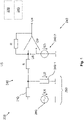
- FIG. 1 3 and 4 parts of a heating system 200 according to the invention for a food processor 1 according to the invention are shown schematically. Furthermore, the serve Figures 1 to 5 for representing a detection device 240 according to the invention and for visualizing a method according to the invention.
- a detection device 240 can have a current measuring device 242 .
- the current measuring device 242 is used to detect an electric current which flows through a heating element 210, in particular a thick-film heater 210, in a load circuit 250 of a heating system 200. According to Ohm's law, this current is linked to an electrical resistance of the heating element 210 and, in particular, is also dependent, and possibly at least for a partial temperature range, is proportional to a temperature of the heating element 210.
- the current measurement (possibly together with a voltage measurement) can thus be used to Heating control can be used, e.g. a control of an energy supply of the heating element 210 by a voltage source 260.
- an in figure 1 U1 marked supply voltage (in particular as an AC voltage) used and / or changed according to the heating control by a control device 220 to a heating of a medium 20 z. B. in a mixing vessel 2 of a food processor 1 to perform.
- an input voltage U2 is shown across the shunt resistor 242.1, which can be amplified by an operational amplifier OP (with a differential voltage U5). If necessary, this is also connected to an offset voltage U3 of a corresponding voltage source 242.2 in order to to obtain the output voltage U4.
- Further resistors R which can also have different resistance values, are optionally provided for the circuit.
- the shunt resistor 242.1 which can be integrated in series with the heating element 210 in the load circuit 250, is used to measure the current.
- a voltage difference U5 which is dependent on the input voltage U2 across the shunt resistor 242.1, is amplified by means of at least one operational amplifier OP, so that an evaluation device 243, in particular an analog-to-digital converter (ADC) of this evaluation device 243, e.g. B. a microprocessor, this can be measured with sufficient accuracy.
- ADC analog-to-digital converter
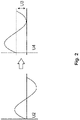
- the operational amplifier OP can be connected to the offset voltage U3, which raises the measurement potential. This is in figure 2 also shown in more detail (the increase is represented there by an arrow). In this way, a current value of a current in the heating element 210 can be determined very reliably using the voltage value of the output voltage U4.
- FIG 3 shows that the detection device 240 can also have a voltage measuring device 241 in order to determine an electrical voltage at the heating element 210 .
- This can include a voltage divider (shown here with an input L, two resistors R and a ground potential GND) in order to provide an input voltage that is not explicitly emphasized as the measurement voltage.
- the circuit shown also includes an active rectifier to compensate for a voltage drop across the in figure 3 shown diodes D, so that voltages below the blocking voltage of the diodes D (z. B. below 0.7 V) can be rectified and measured. This makes it possible to provide a voltage value for controlling the heating element very reliably and with high accuracy.
- the voltage value determined in the circuit shown can be used together with the current value measured by the current measuring device 242 in order to determine a resistance value of a resistor of the heating element 219 .
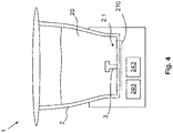
- a food processor 1 is shown schematically, which comprises a mixing vessel 2 into which a medium 20 (with at least one foodstuff) can be filled.
- the mixing vessel 2 can be detachably connected to a receptacle in the food processor 1 are, and have an agitator 3.
- a heating element 210 of a heating system 200 can be integrated in a mixing vessel base 2.1 in order to heat the medium 20.
- An evaluation device 243 and a detection device 240 can also be provided for heating control.
- FIG 5 1 is schematically shown a change characteristic C (with resistance values of a resistor R of the heating element 210 over time t).
- the dashed line shows the determined resistance values of a detected resistance of the heating element 210, based on which a temperature of the heating element 210 or of the medium 20 can be determined. This is compared according to a further curve with a course of a temperature value measured by a separate sensor.
- a heating-up phase 280 can be clearly seen in both curves, whereas the further progression after the heating-up phase 280 differs.
- the formation of a so-called hot spot can only be seen in the dashed curve (thus also according to the temperature determined according to the invention via the resistance of the heating element 210).
- the mixing vessel 2 was tilted so that the medium was only partially in heat-transferring contact with the heating element 210 .
- a similar effect can B. caused by an inhomogeneous medium due to the prepared food.
Landscapes
- Engineering & Computer Science (AREA)
- Food Science & Technology (AREA)
- Mechanical Engineering (AREA)
- Control Of Resistance Heating (AREA)
- Electric Ovens (AREA)
Priority Applications (1)
| Application Number | Priority Date | Filing Date | Title |
|---|---|---|---|
| EP22182127.5A EP4088631A1 (fr) | 2018-01-17 | 2018-01-17 | Procédé permettant de faire fonctionner un élément chauffant |
Applications Claiming Priority (2)
| Application Number | Priority Date | Filing Date | Title |
|---|---|---|---|
| EP22182127.5A EP4088631A1 (fr) | 2018-01-17 | 2018-01-17 | Procédé permettant de faire fonctionner un élément chauffant |
| EP18152116.2A EP3513698B1 (fr) | 2018-01-17 | 2018-01-17 | Procédé de fonctionnement d'un élément chauffant |
Related Parent Applications (1)
| Application Number | Title | Priority Date | Filing Date |
|---|---|---|---|
| EP18152116.2A Division EP3513698B1 (fr) | 2018-01-17 | 2018-01-17 | Procédé de fonctionnement d'un élément chauffant |
Publications (1)
| Publication Number | Publication Date |
|---|---|
| EP4088631A1 true EP4088631A1 (fr) | 2022-11-16 |
Family
ID=61022133
Family Applications (2)
| Application Number | Title | Priority Date | Filing Date |
|---|---|---|---|
| EP18152116.2A Active EP3513698B1 (fr) | 2018-01-17 | 2018-01-17 | Procédé de fonctionnement d'un élément chauffant |
| EP22182127.5A Pending EP4088631A1 (fr) | 2018-01-17 | 2018-01-17 | Procédé permettant de faire fonctionner un élément chauffant |
Family Applications Before (1)
| Application Number | Title | Priority Date | Filing Date |
|---|---|---|---|
| EP18152116.2A Active EP3513698B1 (fr) | 2018-01-17 | 2018-01-17 | Procédé de fonctionnement d'un élément chauffant |
Country Status (5)
| Country | Link |
|---|---|
| US (2) | US11510285B2 (fr) |
| EP (2) | EP3513698B1 (fr) |
| CN (1) | CN110049581B (fr) |
| ES (1) | ES2927247T3 (fr) |
| PL (1) | PL3513698T3 (fr) |
Families Citing this family (4)
| Publication number | Priority date | Publication date | Assignee | Title |
|---|---|---|---|---|
| EP4190212A1 (fr) | 2019-10-15 | 2023-06-07 | Vorwerk & Co. Interholding GmbH | Robot de cuisine et procédé de fonctionnement d'un système de chauffage |
| GB2596791B (en) * | 2020-06-30 | 2024-05-29 | Dyson Technology Ltd | Resistive liquid heater |
| GB2596793B (en) * | 2020-06-30 | 2024-10-16 | Dyson Technology Ltd | Resistive liquid heater |
| CN114073412B (zh) * | 2020-07-31 | 2023-05-09 | 浙江绍兴苏泊尔生活电器有限公司 | 温度检测电路、方法及烹饪器具 |
Citations (4)
| Publication number | Priority date | Publication date | Assignee | Title |
|---|---|---|---|---|
| US3789190A (en) * | 1972-10-17 | 1974-01-29 | A J Matlen | Temperature regulation for electrical heater |
| DE202006020208U1 (de) * | 2006-12-04 | 2008-01-03 | BSH Bosch und Siemens Hausgeräte GmbH | Messvorrichtung |
| WO2008046852A1 (fr) * | 2006-10-19 | 2008-04-24 | BSH Bosch und Siemens Hausgeräte GmbH | Procédé pour la protection d'un élément chauffant ainsi que dispositif de chauffage |
| DE102015101299A1 (de) * | 2015-01-29 | 2016-08-04 | Vorwerk & Co. Interholding Gmbh | Elektrisches Küchengerät |
Family Cites Families (11)
| Publication number | Priority date | Publication date | Assignee | Title |
|---|---|---|---|---|
| KR100784314B1 (ko) * | 2006-12-27 | 2007-12-13 | 웅진쿠첸 주식회사 | Ct 전압의 가변 출력 제어 장치 |
| US7994762B2 (en) * | 2007-12-11 | 2011-08-09 | Analog Devices, Inc. | DC to DC converter |
| NL2001806C2 (en) * | 2008-07-15 | 2010-01-18 | Otter Controls Ltd | Heating element and method for operating such a heating element. |
| EP2146546A1 (fr) * | 2008-07-17 | 2010-01-20 | Microlife Intellectual Property GmbH | Circuit de contrôle de fil de chauffage et procédé de fonctionnement d'un élément chauffant |
| DE102010017335A1 (de) * | 2010-06-11 | 2011-12-15 | Vorwerk & Co. Interholding Gmbh | Küchenmaschine mit einem Rührgefäß sowie Verfahren zum Betreiben einer solchen Küchenmaschine |
| DE102010038361A1 (de) * | 2010-07-23 | 2012-01-26 | Robert Bosch Gmbh | Verfahren zur Messung der Temperatur eines Mediums und Temperatursensor |
| US8921747B2 (en) * | 2011-03-14 | 2014-12-30 | Electrolux Home Products, Inc. | Electric heating appliance with AC-line filter with low leakage current |
| EP2500724B1 (fr) * | 2011-03-17 | 2014-04-30 | Electrolux Home Products Corporation N.V. | Procédé pour obtenir des informations sur des aliments dans ou pour un processus de cuisson |
| CN104456654B (zh) * | 2013-09-13 | 2017-01-11 | 美的集团股份有限公司 | 电磁炉及其控制方法 |
| US10165894B2 (en) * | 2016-07-10 | 2019-01-01 | Peigen Jiang | Automated cooker |
| CN107145182B (zh) * | 2017-05-19 | 2018-11-06 | 北京东方计量测试研究所 | 输入电压型模拟电阻器及电阻控制方法 |
-
2018
- 2018-01-17 PL PL18152116.2T patent/PL3513698T3/pl unknown
- 2018-01-17 ES ES18152116T patent/ES2927247T3/es active Active
- 2018-01-17 EP EP18152116.2A patent/EP3513698B1/fr active Active
- 2018-01-17 EP EP22182127.5A patent/EP4088631A1/fr active Pending
-
2019
- 2019-01-16 CN CN201910039278.2A patent/CN110049581B/zh active Active
- 2019-01-17 US US16/250,996 patent/US11510285B2/en active Active
-
2022
- 2022-11-09 US US18/054,122 patent/US11903096B2/en active Active
Patent Citations (4)
| Publication number | Priority date | Publication date | Assignee | Title |
|---|---|---|---|---|
| US3789190A (en) * | 1972-10-17 | 1974-01-29 | A J Matlen | Temperature regulation for electrical heater |
| WO2008046852A1 (fr) * | 2006-10-19 | 2008-04-24 | BSH Bosch und Siemens Hausgeräte GmbH | Procédé pour la protection d'un élément chauffant ainsi que dispositif de chauffage |
| DE202006020208U1 (de) * | 2006-12-04 | 2008-01-03 | BSH Bosch und Siemens Hausgeräte GmbH | Messvorrichtung |
| DE102015101299A1 (de) * | 2015-01-29 | 2016-08-04 | Vorwerk & Co. Interholding Gmbh | Elektrisches Küchengerät |
Also Published As
| Publication number | Publication date |
|---|---|
| US11510285B2 (en) | 2022-11-22 |
| US20230116252A1 (en) | 2023-04-13 |
| EP3513698A1 (fr) | 2019-07-24 |
| EP3513698B1 (fr) | 2022-07-13 |
| US20190223258A1 (en) | 2019-07-18 |
| ES2927247T3 (es) | 2022-11-03 |
| CN110049581A (zh) | 2019-07-23 |
| US11903096B2 (en) | 2024-02-13 |
| CN110049581B (zh) | 2022-04-12 |
| PL3513698T3 (pl) | 2022-11-21 |
Similar Documents
| Publication | Publication Date | Title |
|---|---|---|
| EP3513698B1 (fr) | Procédé de fonctionnement d'un élément chauffant | |
| EP2661944B1 (fr) | Appareil de cuisson à induction destiné à une cuisson par commande de température | |
| DE3811925C1 (fr) | ||
| DE102008038783B4 (de) | Küchenmaschine mit einem Rührgefäß sowie Verfahren hierzu | |
| EP3468436B1 (fr) | Procédé pour faire fonctionner un robot ménager | |
| DE69811353T2 (de) | Erhitzungsgefäss und verfahren zum regulieren des erhitzungselementes eines solchen gefässes. | |
| DE112016000542T5 (de) | Nahrungsmittelzubereitungssteuerungs-system | |
| DE19648397A1 (de) | Verfahren und Vorrichtung zum Erkennen des Kochpunktes von Kochgut | |
| EP3013120B2 (fr) | Plaque de cuisson | |
| DE2949890C2 (fr) | ||
| DE3104926C2 (de) | Steuereinrichtung für Koch-, Brat- oder Backvorgänge mit einem Speisethermometer | |
| DE102017214753A1 (de) | Haushalts-Gargerät | |
| DE102015101707B4 (de) | Kochsystem und Verfahren zum Betreiben eines Kochsystems | |
| DE102005023468A1 (de) | Gargerät mit Temperaturerfassungsvorrichtung | |
| EP0806887B1 (fr) | Procédé et dispositif pour reconnaítre le stade de cuisson d'aliments à cuire | |
| DE102014103480B4 (de) | Gargerät und Verfahren zum Betreiben eines Gargerätes | |
| DE112007001158B4 (de) | Vorrichtung und Verfahren zur Steuerung und/oder Regelung einer Heizleistung eines Heizelements einer Kochmulde | |
| EP3001163A1 (fr) | Dispositif d'appareil de cuisson | |
| EP3115758B1 (fr) | Capteur de cuisson amovible | |
| DE102018212441A1 (de) | Auftaumatte, Haushaltsgerät mit einer Auftaumatte, Verfahren zum Auftauen und Verfahren zum Zubereiten von Lebensmitteln | |
| EP1768461B1 (fr) | Méthode pour générer, traiter et évaluer un signal en correlation avec la température, et dispositif correspondant | |
| EP4119909B1 (fr) | Thermomètre alimentaire et procédé de préparation des aliments | |
| EP2639512B1 (fr) | Appareil ménager avec une sonde lambda ou procédé de fonctionnement d'un appareil ménager avec une sonde lambda | |
| EP3250001B1 (fr) | Appareil de cuisson ménager | |
| DE19643714C2 (de) | Vorrichtung zum Regeln des Garvorgangs von zu garendem Gut |
Legal Events
| Date | Code | Title | Description |
|---|---|---|---|
| PUAI | Public reference made under article 153(3) epc to a published international application that has entered the european phase |
Free format text: ORIGINAL CODE: 0009012 |
|
| STAA | Information on the status of an ep patent application or granted ep patent |
Free format text: STATUS: THE APPLICATION HAS BEEN PUBLISHED |
|
| AC | Divisional application: reference to earlier application |
Ref document number: 3513698 Country of ref document: EP Kind code of ref document: P |
|
| AK | Designated contracting states |
Kind code of ref document: A1 Designated state(s): AL AT BE BG CH CY CZ DE DK EE ES FI FR GB GR HR HU IE IS IT LI LT LU LV MC MK MT NL NO PL PT RO RS SE SI SK SM TR |
|
| STAA | Information on the status of an ep patent application or granted ep patent |
Free format text: STATUS: REQUEST FOR EXAMINATION WAS MADE |
|
| 17P | Request for examination filed |
Effective date: 20221128 |
|
| RBV | Designated contracting states (corrected) |
Designated state(s): AL AT BE BG CH CY CZ DE DK EE ES FI FR GB GR HR HU IE IS IT LI LT LU LV MC MK MT NL NO PL PT RO RS SE SI SK SM TR |
|
| STAA | Information on the status of an ep patent application or granted ep patent |
Free format text: STATUS: EXAMINATION IS IN PROGRESS |
|
| 17Q | First examination report despatched |
Effective date: 20250212 |