EP4088933B1 - Dispositif d'impression à jet d'encre et procédé de fabrication associé - Google Patents
Dispositif d'impression à jet d'encre et procédé de fabrication associé Download PDFInfo
- Publication number
- EP4088933B1 EP4088933B1 EP20912797.6A EP20912797A EP4088933B1 EP 4088933 B1 EP4088933 B1 EP 4088933B1 EP 20912797 A EP20912797 A EP 20912797A EP 4088933 B1 EP4088933 B1 EP 4088933B1
- Authority
- EP
- European Patent Office
- Prior art keywords
- nozzle
- ink
- pressure
- recording device
- inkjet recording
- Prior art date
- Legal status (The legal status is an assumption and is not a legal conclusion. Google has not performed a legal analysis and makes no representation as to the accuracy of the status listed.)
- Active
Links
Images

Classifications
-
- B—PERFORMING OPERATIONS; TRANSPORTING
- B41—PRINTING; LINING MACHINES; TYPEWRITERS; STAMPS
- B41J—TYPEWRITERS; SELECTIVE PRINTING MECHANISMS, i.e. MECHANISMS PRINTING OTHERWISE THAN FROM A FORME; CORRECTION OF TYPOGRAPHICAL ERRORS
- B41J2/00—Typewriters or selective printing mechanisms characterised by the printing or marking process for which they are designed
- B41J2/005—Typewriters or selective printing mechanisms characterised by the printing or marking process for which they are designed characterised by bringing liquid or particles selectively into contact with a printing material
- B41J2/01—Ink jet
- B41J2/17—Ink jet characterised by ink handling
- B41J2/18—Ink recirculation systems
-
- B—PERFORMING OPERATIONS; TRANSPORTING
- B41—PRINTING; LINING MACHINES; TYPEWRITERS; STAMPS
- B41J—TYPEWRITERS; SELECTIVE PRINTING MECHANISMS, i.e. MECHANISMS PRINTING OTHERWISE THAN FROM A FORME; CORRECTION OF TYPOGRAPHICAL ERRORS
- B41J2/00—Typewriters or selective printing mechanisms characterised by the printing or marking process for which they are designed
- B41J2/005—Typewriters or selective printing mechanisms characterised by the printing or marking process for which they are designed characterised by bringing liquid or particles selectively into contact with a printing material
- B41J2/01—Ink jet
- B41J2/015—Ink jet characterised by the jet generation process
- B41J2/04—Ink jet characterised by the jet generation process generating single droplets or particles on demand
- B41J2/045—Ink jet characterised by the jet generation process generating single droplets or particles on demand by pressure, e.g. electromechanical transducers
- B41J2/04501—Control methods or devices therefor, e.g. driver circuits, control circuits
- B41J2/04533—Control methods or devices therefor, e.g. driver circuits, control circuits controlling a head having several actuators per chamber
-
- B—PERFORMING OPERATIONS; TRANSPORTING
- B41—PRINTING; LINING MACHINES; TYPEWRITERS; STAMPS
- B41J—TYPEWRITERS; SELECTIVE PRINTING MECHANISMS, i.e. MECHANISMS PRINTING OTHERWISE THAN FROM A FORME; CORRECTION OF TYPOGRAPHICAL ERRORS
- B41J2/00—Typewriters or selective printing mechanisms characterised by the printing or marking process for which they are designed
- B41J2/005—Typewriters or selective printing mechanisms characterised by the printing or marking process for which they are designed characterised by bringing liquid or particles selectively into contact with a printing material
- B41J2/01—Ink jet
- B41J2/135—Nozzles
- B41J2/14—Structure thereof only for on-demand ink jet heads
- B41J2/14451—Structure of ink jet print heads discharging by lowering surface tension of meniscus
-
- B—PERFORMING OPERATIONS; TRANSPORTING
- B41—PRINTING; LINING MACHINES; TYPEWRITERS; STAMPS
- B41J—TYPEWRITERS; SELECTIVE PRINTING MECHANISMS, i.e. MECHANISMS PRINTING OTHERWISE THAN FROM A FORME; CORRECTION OF TYPOGRAPHICAL ERRORS
- B41J2/00—Typewriters or selective printing mechanisms characterised by the printing or marking process for which they are designed
- B41J2/005—Typewriters or selective printing mechanisms characterised by the printing or marking process for which they are designed characterised by bringing liquid or particles selectively into contact with a printing material
- B41J2/01—Ink jet
- B41J2/17—Ink jet characterised by ink handling
- B41J2/175—Ink supply systems ; Circuit parts therefor
-
- B—PERFORMING OPERATIONS; TRANSPORTING
- B41—PRINTING; LINING MACHINES; TYPEWRITERS; STAMPS
- B41J—TYPEWRITERS; SELECTIVE PRINTING MECHANISMS, i.e. MECHANISMS PRINTING OTHERWISE THAN FROM A FORME; CORRECTION OF TYPOGRAPHICAL ERRORS
- B41J2/00—Typewriters or selective printing mechanisms characterised by the printing or marking process for which they are designed
- B41J2/005—Typewriters or selective printing mechanisms characterised by the printing or marking process for which they are designed characterised by bringing liquid or particles selectively into contact with a printing material
- B41J2/01—Ink jet
- B41J2/135—Nozzles
- B41J2/14—Structure thereof only for on-demand ink jet heads
- B41J2002/14338—Multiple pressure elements per ink chamber
Definitions
- the present invention relates to an inkjet recording device and a manufacturing method thereof.
- Patent Document 1 the pressure of ink in the vicinity of the opening of a nozzle is maintained at an appropriate pressure as follows. That is, an appropriate pressure (Pn) of the ink in the vicinity of the opening of the nozzle is made at the atmospheric pressure or lower by maintaining a relation of a pressure source (P1) on an upstream side, a pressure source (P2) on a downstream side, and the appropriate pressure (Pn) in accordance with a disclosed relation formula that uses a ratio of flow path resistances on an upstream side and a downstream side of a branch point to the nozzle in an ink flow path.
- Patent Document 2 discloses an inkjet device with a control device which changes at least one of energies per unit volume of first and second pressure sources.
- Patent Document 1 the relation formula of P1, P2, and Pn disclosed in Patent Document 1 is established only in a flow path structure having no branch in an ink flow path from a pressure source (P1) on an upstream side to a pressure source (P2) on a downstream side, as illustrated in FIG. 4 .
- the relation formula of P1, P2, and Pn disclosed in Patent Document 1 does not hold in a flow path structure in which a pressure source (P1) on an upstream side and a pressure source (P2) on a downstream side are connected by an ink flow path that branches into a flow path (flow path resistances R4 and R5) passing through a nozzle "N” and a flow path (flow path resistance R3) bypassing the nozzle "N", as illustrated in FIG. 5 .
- Patent Document 1 requires obtaining a relation formula of P1, P2, and Pn for each of inkjet heads having different flow path structures.
- the present invention has been made in view of the above-described problem in the conventional technique, and an object of the present invention is to enable easily maintaining an appropriate ink pressure in the vicinity of an opening of a nozzle, irrespective of a flow path structure, in an inkjet recording device.
- a first aspect of the present invention for solving the problem described above provides an inkjet recording device including at least one inkjet head, a first pressure source, a second pressure source, and a controller.
- the inkjet head has a pressure chamber that communicates with a nozzle and is configured to eject ink from the nozzle.
- the ink communicates with the pressure chamber.
- the first pressure source is configured to adjust energy per unit volume of the ink so that the ink generates "energy per unit volume" P1(Pa), relative to static ink at the atmospheric pressure at a position having a height of an opening of the nozzle.
- the second pressure source is configured to adjust energy per unit volume of the ink so that the ink generates "energy per unit volume" P2(Pa), relative to static ink at the atmospheric pressure at the position having the height of the opening of the nozzle.
- the first pressure source, the pressure chamber, and the second pressure source are connected in this order by a flow path.
- a limit value of P1 at which the ink overflows from the nozzle during non-circulation due to the differential pressure (P1 - P2) being 0(Pa) is P11
- a limit value of P1 at which the ink overflows from the nozzle during circulation due to the differential pressure (P1 - P2) being any value other than 0 is P12
- a pressure loss occurring at the time of ejecting the ink from the nozzle is ⁇ Pb
- the diameter of the nozzle is "d”
- the surface tension of the ink is ⁇
- Pn is a value less than 0(Pa) and greater than a value obtained from -(4 ⁇ /d - a(P1 - P2) - ⁇ Pb).
- a limit value of P1 at which air bubbles are caught from the nozzle at the time of non-ejection during circulation is P13
- a limit value of P1 at which air bubbles are caught from the nozzle at the time of ejection during circulation is P14
- a fifth aspect of the present invention provides a method for manufacturing an inkjet recording device.
- the inkjet recording device includes at least one inkjet head, a first pressure source, and a second pressure source.
- the inkjet head has a pressure chamber that communicates with a nozzle and is configured to eject ink from the nozzle.
- the ink communicates with the pressure chamber.
- the first pressure source is configured to adjust energy per unit volume of the ink so that the ink generates "energy per unit volume" P1(Pa), relative to static ink at the atmospheric pressure at a position having a height of an opening of the nozzle.
- the second pressure source is configured to adjust energy per unit volume of the ink so that the ink generates "energy per unit volume" P2(Pa), relative to static ink at the atmospheric pressure at the position having the height of the opening of the nozzle.
- the first pressure source, the pressure chamber, and the second pressure source are connected in this order by a flow path.
- the method includes assuming that a pressure loss occurring from the first pressure source to the nozzle due to a circulation flow rate is ⁇ Pa, calculating a constant of proportionality "a" of a differential pressure (P1 - P2) and ⁇ Pa.
- the method for manufacturing the inkjet recording device also includes, assuming that a limit value of P1 at which the ink overflows from the nozzle during non-circulation due to the differential pressure (P1 - P2) being 0(Pa) is P11, and a limit value of P1 at which the ink overflows from the nozzle during circulation due to the differential pressure (P1 - P2) being any value other than 0 is P12,
- the method for manufacturing the inkjet recording device further includes, assuming that a pressure loss occurring at the time of ejecting the ink from the nozzle is ⁇ Pb, the diameter of the nozzle is "d", and the surface tension of the ink is ⁇ , setting Pn at a value less than 0(Pa) and greater than a value obtained from -(4 ⁇ /d - a(P1 - P2) - ⁇ Pb).
- the method for manufacturing the inkjet recording device further includes, assuming that a limit value of P1 at which air bubbles are caught from the nozzle at the time of non-ejection during circulation is P13, and a limit value of P1 at which air bubbles are caught from the nozzle at the time of ejection during circulation is P14,
- the present invention enables easily maintaining an appropriate ink pressure in the vicinity of an opening of a nozzle, irrespective of a flow path structure, in an inkjet recording device.
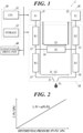
- an inkjet recording device 1 of this embodiment includes an inkjet head 10, an ink supply unit 20, a controller 30, and a conveyance drive unit 40.
- the inkjet head 10 includes a nozzle "N” and a pressure chamber 11 that communicates with the nozzle "N".
- the inkjet head 10 performs operation such as recording operation for recording an image, etc., on a recording medium by ejecting ink from the nozzle "N".
- the ink communicates with the pressure chamber 11 and is ejected by the action of a drive element, such as a piezoelectric element.
- a drive element such as a piezoelectric element.
- At least one inkjet head 10 is provided, but a plurality of inkjet heads 10 may be provided.
- the pressure that is generated in the vicinity of the opening of the nozzle "N" is represented as "Pn".
- the conveyance drive unit 40 moves a target recording medium on which an image is to be recorded by the inkjet head 10, relative to the nozzle "N" of the inkjet head 10.
- the ink supply unit 20 includes a first pressure source 21 and a second pressure source 22.
- the first pressure source 21 communicates with a first flow path 12 and adjusts energy per unit volume of ink so that the ink will generate "energy per unit volume" P1(Pa), relative to static ink at the atmospheric pressure at a position having the height of the opening of the nozzle "N".
- the second pressure source 22 communicates with a second flow path 13 and adjusts energy per unit volume of ink so that the ink will generate "energy per unit volume" P2(Pa), relative to static ink at the atmospheric pressure at a position having the height of the opening of the nozzle "N".
- the first pressure source 21 and the second pressure source 22 include ink chambers that are positioned at a predetermined height relative to the position having the height of the opening of the nozzle "N".
- the first pressure source 21 and the second pressure source 22 also include components such as an ink tank, a pump, a control valve, and a sensor, for controlling inflow and outflow of ink to the ink chamber and controlling pressure applied to a liquid surface in the ink chamber.
- the controller 30 includes a central processing unit (CPU) 31 and a storage 32 and collectively controls various operations of the inkjet recording device 1.
- the operations of the inkjet recording device 1 to be controlled include supply and circulation of ink, image recording operation, and maintenance operation of the inkjet head 10.
- the CPU 31 executes a control process by performing various arithmetic calculations.
- the storage 32 includes, for example, a random access memory (RAM) and a nonvolatile memory.
- the RAM provides a working memory space to the CPU 31 and stores temporary data.
- the nonvolatile memory stores and holds various control programs and setting data.
- the nonvolatile memory is, for example, a flash memory, and may include a hard disk drive (HDD).
- the flow path structure illustrated in FIG. 1 is an example and has the following configuration.
- the first pressure source 21 is connected to the pressure chamber 11 via the first flow path 12 and a fourth flow path 15.
- the pressure chamber 11 is connected to the second pressure source 22 via a fifth flow path 16 and a second flow path 13.
- the connection point between the first flow path 12 and the fourth flow path 15 and the connection point between the second flow path 13 and the fifth flow path 16 are connected by a third flow path 14 without passing the pressure chamber 11.
- each of the first flow path 12 and the second flow path 13 includes a head outside flow path that connects the head 10 and the pressure source (the same applies to the case in FIGs. 4 and 5 ).
- these flow path resistances R1 to R5 are not used, and the flow path structure is not limited to that described above.
- the present invention can be applied to various flow path structures in addition to the flow path structure illustrated in FIG. 4 .
- the controller 30 controls the pressures P1 and P2 as described below.
- the controller 30 variably controls the values P1 and P2 to make them different values, in accordance with the formula (3).
- the controller 30 variably controls the values P1 and P2 that satisfy the relation of the formula (3), between values P1 and P2 for a high flow speed due to a high differential pressure (P1 - P2) and values P1 and P2 for a low flow speed due to a low differential pressure (P1 - P2), while Pn is in an appropriate range.
- the ⁇ Pa has the following relation.
- FIG. 2 illustrates a graph showing the proportional relationship between the differential pressure (P1 - P2) and the pressure loss ⁇ Pa.
- the P11 and P12 are determined by varying the values P1 and P2 while maintaining the differential pressure (P1 - P2) at any value.
- the pressure losses ⁇ Pa respectively corresponding to a plurality of differential pressures (P1 - P2) are calculated from the formula (4), and the constant of proportionality "a" is calculated from a correlation of these plurality of pairs of the differential pressure (P1 - P2) and ⁇ Pa.
- ink is ejected from the nozzle "N" during circulation when the differential pressure (P1 - P2) is any value other than 0.
- the appropriate pressure Pn is a value less than 0(Pa) and greater than a value obtained from ⁇ 4 ⁇ /d ⁇ a P1 ⁇ P2 ⁇ ⁇ Pb
- the P13 and P14 are determined by varying the values P1 and P2 while maintaining the differential pressure (P1 - P2) at any value other than 0.
- the values of P1 and P2 are varied while maintaining the differential pressure (P1 - P2) at any value other than 0, to increase the degree of intake of the outside air from the nozzle "N” in conjunction with reaction of ejection operation. Then, a limit of occurrence of catching air bubbles from the nozzle "N” comes.
- the value of P1 at this time is used as P14.
- the ⁇ Pb is calculated from the formula (6).
- the controller 30 controls pressure in accordance with the range of the appropriate pressure Pn, which is thus determined, and the formula (3). As a result, a meniscus that is formed at the opening of the nozzle "N" is suitably maintained.
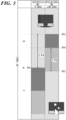
- the vertical axis illustrated in FIG. 3 shows a magnitude of P1.
- the P1 is assumed to be of an ink supply side.
- the vertical bar B1 on the right side of the vertical axis shows a pressure range of each state and a boundary (limit value) of the pressure range in the condition in which the differential pressure (P1 - P2) is 0(kPa).
- the vertical bar B2 on the most right side shows a pressure range of each state and a boundary (limit value) of the pressure range in the condition in which the differential pressure (P1 - P2) is ⁇ Pd(kPa). Note that ⁇ Pd ⁇ 0.
- ink can overflow from the nozzle "N".
- ink can overflow from the nozzle "N”.
- the difference between P12 and P11 corresponds to the pressure loss ⁇ Pa that occurs from the first pressure source 21 to the nozzle "N" due to the circulation flow rate.
- the pressure loss ⁇ Pa can be calculated from the difference between the pressures P11 and P12 at the same phenomenon in which ink overflows from the nozzle "N", in the bars B1 and B2.
- the pressure value P13 in the bar B2 corresponds to a limit value (static meniscus braking pressure), and air bubbles are caught if P1 falls below this limit value while ink is not ejected.
- the pressure value P14 in the bar B2 corresponds to a limit value (dynamic meniscus braking pressure), and air bubbles are caught at the time of ejecting ink if P1 falls below this limit value.
- the difference between P14 and P13 corresponds to the pressure loss ⁇ Pb that occurs at the time of ejecting ink from the nozzle "N".
- P1 in the range of P12 to P14 in order to prevent overflow of ink from the nozzle "N” and to prevent intake of air bubbles although ink is ejected, in image recording operation.
- P1 in the range of P12 to P14 in order to prevent overflow of ink from the nozzle "N” and to prevent intake of air bubbles although ink is ejected, in image recording operation.
- a meniscus that is formed at the opening of the nozzle "N” is maintained by the pressure 4 ⁇ /d due to the surface tension, although the pressure losses ⁇ Pa and ⁇ Pb occur.
- the appropriate pressure Pn is less 0(Pa) and greater than the value obtained from the formula (5).
- the formula (3) is used after the constant of proportionality "a” and the appropriate pressure Pn are calculated as described above, and design is performed so that the relation of the formula (3) will be established.
- the constant of proportionality "a” does not depend on physical properties of ink on the condition that the flow path structure is the same. In consideration of this, the constant of proportionality "a” should be examined at least once with respect to the same type of inkjet heads having the same flow path structure.
- the pressure chart illustrated in FIG. 3 differs depending on the setting of the differential pressure (P1 - P2) during image recording operation and on physical properties of ink, and therefore, the appropriate pressure Pn is calculated for each of these conditions.
- An inkjet recording device including a controller that has a control function for variably controlling P1, P2, and Pn while maintaining the relation of the formula (3), may be manufactured, or an inkjet recording device including an ink supply unit that moves so that the relation of the formula (3) will be established during operation, may be manufactured.
- this embodiment enables easily maintaining an appropriate ink pressure in the vicinity of an opening of a nozzle, irrespective of a flow path structure, in an inkjet recording device.
- the present invention can be used in inkjet recording devices.
Landscapes
- Ink Jet (AREA)
- Particle Formation And Scattering Control In Inkjet Printers (AREA)
Claims (8)
- Dispositif d'enregistrement à jet d'encre (1) comprenant :au moins une tête à jet d'encre (10) comportant une chambre de pression (11) qui communique avec une buse (N) et qui est configurée pour éjecter de l'encre de la buse, l'encre communiquant avec la chambre de pression ;une première source de pression (21) configurée pour ajuster de l'énergie par unité de volume de l'encre de sorte que l'encre génère "énergie par unité de volume" P1(Pa), par rapport à de l'encre statique à une pression atmosphérique à une position ayant une hauteur d'une ouverture de la buse ;une deuxième source de pression (22) configurée pour ajuster de l'énergie par unité de volume de l'encre de sorte que l'encre génère "énergie par unité de volume" P2(Pa), par rapport à de l'encre statique à une pression atmosphérique à la position ayant la hauteur de l'ouverture de la buse ; etun contrôleur (30), caractérisé en ce quela première source de pression, la chambre de pression et la deuxième source de pression sont reliées dans cet ordre par une voie d'écoulement,en supposant qu'une perte de pression se produisant de la première source de pression à la buse en raison d'un débit d'écoulement de circulation est ΔPa, qu'une constante de proportionnalité d'une pression différentielle (P1 - P2) et ΔPa est "a", et qu'une pression appropriée qui est générée dans la vicinité de l'ouverture de la buse est Pn, le contrôleur est configuré pour contrôler la pression de manière qu'une relation P2 = {Pn - (1 - a) P1} / a est établie.
- Dispositif d'enregistrement à jet d'encre selon la revendication 1, dans lequel, en supposant qu'une valeur limite de P1 à laquelle l'encre déborde de la buse pendant la non-circulation en raison de la pression différentielle (P1 - P2) étant 0(Pa) est P11, et qu'une valeur limite de P1 à laquelle l'encre déborde de la buse pendant la circulation en raison de la pression différentielle (P1 - P2) étant toute valeur autre que 0 est P12, une relation ΔPa = |P12 - P11| est établie.
- Dispositif d'enregistrement à jet d'encre selon la revendication 1 ou 2, dans lequel, en supposant qu'une perte de pression se produisant au moment d'éjection de l'encre de la buse est ΔPb, qu'un diamètre de la buse est "d" et qu'une tension de surface de l'encre est σ, Pn is est une valeur inférieure à 0(Pa) et supérieure à une valeur obtenue à partir de-(4σ/d - a(P1 - P2) - ΔPb).
- Dispositif d'enregistrement à jet d'encre selon la revendication 3, dans lequel, en supposant qu'une valeur limite de P1 à laquelle des bulles d'air sont capturées de la buse au moment de non-éjection pendant la circulation est P13, et qu'une valeur limite de P1 à laquelle des bulles d'air sont capturées de la buse au moment d'éjection pendant la circulation est P14, une relation ΔPb = IP14 - P13| est établie.
- Procédé de fabrication d'un dispositif d'enregistrement à jet d'encre (1),
le dispositif d'enregistrement à jet d'encre comprenant :au moins une tête à jet d'encre (10) ayant une chambre de pression (11) qui communique avec une buse (N) et étant configurée pour éjecter de l'encre de la buse, l'encre communiquant avec la chambre de pression ;une première source de pression (21) configurée pour ajuster de l'énergie par unité de volume de l'encre de sorte que l'encre génère "énergie par unité de volume" P1(Pa), par rapport à l'encre statique à une pression atmosphérique à une position ayant une hauteur d'une ouverture de la buse ; etune seconde source de pression (22) configurée pour ajuster de l'énergie par unité de volume de l'encre de sorte que l'encre génère "énergie par unité de volume" P2(Pa), par rapport à l'encre statique à une pression atmosphérique à la position ayant la hauteur de l'ouverture de la buse, caractérisée en ce quela première source de pression, la chambre de pression et la deuxième source de pression étant reliées dans cet ordre par une voie d'écoulement,le procédé comprend :supposer qu'une perte de pression se produisant de la première source de pression à la buse en raison d'un débit d'écoulement de circulation est ΔPa, calculer une constante de proportionnalité "a" d'une pression différentielle (P1 - P2) et ΔPa ; etsupposer qu'une pression appropriée qui est générée dans la vicinité de l'ouverture de la buse est Pn,concevoir de manière qu'une relation P2 = {Pn - (1 - a) P1} / a est établie. - Le procédé de fabrication du dispositif d'enregistrement à jet d'encre selon la revendication 5, comprenant en outre :supposer qu'une valeur limite de P1 à laquelle l'encre déborde de la buse pendant la non-circulation en raison de la pression différentielle (P1 - P2) étant 0(Pa) est P11, et qu'une valeur limite de P1 à laquelle l'encre déborde de la buse pendant la circulation en raison de la pression différentielle (P1 - P2) étant toute valeur autre que 0 est P12,déterminer P11 et P12 en faisant varier les valeurs P1 et P2 tout en maintenant la pression différentielle (P1 - P2) à une valeur quelconque ;calculer ΔPa à partir d'une relation ΔPa = |P12 - P11| ; etcalculer "a" à partir d'une corrélation entre la pression différentielle (P1 - P2) et ΔPa.
- La méthode de fabrication du dispositif d'enregistrement à jet d'encre selon la revendication 5 ou 6, comprenant en outre,supposer qu'une perte de pression se produisant au moment d'éjection de l'encre de la buse est ΔPb, qu'un diamètre de la buse est "d", et qu'une tension de surface de l'encre est σ,fixer Pn à une valeur inférieure à 0(Pa) et supérieure à une valeur obtenue à partir de -(4σ/d - a(P1 - P2) - ΔPb).
- Le procédé de fabrication du dispositif d'enregistrement à jet d'encre selon la revendication 7, comprenant en outre :supposer qu'une valeur limite de P1 à laquelle des bulles d'air sont capturées de la buse au moment de non-éjection pendant la circulation est P13, et qu'une valeur limite de P1 à laquelle les bulles d'air sont capturées de la buse au moment d'éjection pendant la circulation est P14,déterminer P13 et P14 en faisant varier les valeurs P1 et P2 tout en maintenant la pression différentielle (P1 - P2) à toute valeur autre que 0 ; etcalculer ΔPb à partir d'une relation ΔPb = |P14 - P13|.
Applications Claiming Priority (1)
| Application Number | Priority Date | Filing Date | Title |
|---|---|---|---|
| PCT/JP2020/000650 WO2021140646A1 (fr) | 2020-01-10 | 2020-01-10 | Dispositif d'impression à jet d'encre et procédé de fabrication associé |
Publications (3)
| Publication Number | Publication Date |
|---|---|
| EP4088933A1 EP4088933A1 (fr) | 2022-11-16 |
| EP4088933A4 EP4088933A4 (fr) | 2022-12-14 |
| EP4088933B1 true EP4088933B1 (fr) | 2025-02-19 |
Family
ID=76787794
Family Applications (1)
| Application Number | Title | Priority Date | Filing Date |
|---|---|---|---|
| EP20912797.6A Active EP4088933B1 (fr) | 2020-01-10 | 2020-01-10 | Dispositif d'impression à jet d'encre et procédé de fabrication associé |
Country Status (5)
| Country | Link |
|---|---|
| US (1) | US11975533B2 (fr) |
| EP (1) | EP4088933B1 (fr) |
| JP (1) | JP7484936B2 (fr) |
| CN (1) | CN114929481B (fr) |
| WO (1) | WO2021140646A1 (fr) |
Families Citing this family (2)
| Publication number | Priority date | Publication date | Assignee | Title |
|---|---|---|---|---|
| WO2026079340A1 (fr) * | 2024-10-07 | 2026-04-16 | コニカミノルタ株式会社 | Dispositif d'impression à jet d'encre et procédé de détection d'anomalie dans une partie de trajet d'écoulement d'une tête à jet d'encre |
| WO2026079339A1 (fr) * | 2024-10-07 | 2026-04-16 | コニカミノルタ株式会社 | Dispositif d'impression à jet d'encre et procédé de détection d'anomalie de partie de trajet d'écoulement de tête à jet d'encre |
Family Cites Families (12)
| Publication number | Priority date | Publication date | Assignee | Title |
|---|---|---|---|---|
| JP3408060B2 (ja) * | 1995-09-22 | 2003-05-19 | キヤノン株式会社 | 液体吐出方法および装置とこれらに用いられる液体吐出ヘッド |
| JP3419220B2 (ja) * | 1996-10-15 | 2003-06-23 | セイコーエプソン株式会社 | インクジェット式記録装置 |
| JP2001088279A (ja) * | 1999-09-20 | 2001-04-03 | Fuji Photo Film Co Ltd | 画像形成方法および装置 |
| KR100657950B1 (ko) * | 2005-02-05 | 2006-12-14 | 삼성전자주식회사 | 잉크 공급 장치와 이를 구비한 잉크젯 프린트헤드 패키지 |
| US7597434B2 (en) * | 2006-04-27 | 2009-10-06 | Toshiba Tec Kabushiki Kaisha | Ink-jet apparatus and method of the same |
| JP5728148B2 (ja) | 2006-04-27 | 2015-06-03 | 東芝テック株式会社 | インクジェット装置およびその制御方法 |
| US7850290B2 (en) * | 2006-12-28 | 2010-12-14 | Toshiba Tec Kabushiki Kaisha | Ink jet recording apparatus, ink supplying mechanism and ink supplying method |
| US8262209B2 (en) * | 2008-05-28 | 2012-09-11 | Toshiba Tec Kabushiki Kaisha | Circulating type ink supply system |
| US8876243B2 (en) * | 2010-09-13 | 2014-11-04 | Toshiba Tec Kabushiki Kaisha | Inkjet recording device and inkjet recording method |
| US9895897B2 (en) | 2013-08-27 | 2018-02-20 | Hewlett-Packard Development Company, L.P. | Selectively provide pressure differences between reservoirs to cause printing fluid movement |
| JP6286387B2 (ja) | 2015-04-27 | 2018-02-28 | 株式会社東芝 | インクジェット装置 |
| US10792930B2 (en) * | 2017-09-29 | 2020-10-06 | Canon Kabushiki Kaisha | Liquid ejection apparatus and liquid ejection head |
-
2020
- 2020-01-10 EP EP20912797.6A patent/EP4088933B1/fr active Active
- 2020-01-10 WO PCT/JP2020/000650 patent/WO2021140646A1/fr not_active Ceased
- 2020-01-10 US US17/792,002 patent/US11975533B2/en active Active
- 2020-01-10 CN CN202080092331.6A patent/CN114929481B/zh active Active
- 2020-01-10 JP JP2021569689A patent/JP7484936B2/ja active Active
Also Published As
| Publication number | Publication date |
|---|---|
| EP4088933A4 (fr) | 2022-12-14 |
| CN114929481A (zh) | 2022-08-19 |
| JP7484936B2 (ja) | 2024-05-16 |
| WO2021140646A1 (fr) | 2021-07-15 |
| CN114929481B (zh) | 2023-08-08 |
| US11975533B2 (en) | 2024-05-07 |
| EP4088933A1 (fr) | 2022-11-16 |
| JPWO2021140646A1 (fr) | 2021-07-15 |
| US20230040662A1 (en) | 2023-02-09 |
Similar Documents
| Publication | Publication Date | Title |
|---|---|---|
| EP4088933B1 (fr) | Dispositif d'impression à jet d'encre et procédé de fabrication associé | |
| JP5153369B2 (ja) | 画像形成装置 | |
| JP6996164B2 (ja) | 液体を吐出する装置 | |
| JP6450942B2 (ja) | インクジェット装置とインクジェット方法 | |
| JP2019014174A5 (fr) | ||
| US20170043589A1 (en) | Method for damping pressure peaks in a line for ink of an inkjet printer | |
| KR20190029447A (ko) | 잉크젯 헤드와 그것을 이용한 잉크젯 장치와 디바이스의 제조 방법 | |
| US20150191021A1 (en) | Liquid discharge apparatus and liquid supply path state detection method | |
| US10232632B2 (en) | Liquid ejection apparatus and liquid ejection head | |
| EP3213919A1 (fr) | Atténuation des effets de la diaphonie dans une tête d'impression à jet d'encre | |
| JP6672002B2 (ja) | 液体吐出装置および制御方法 | |
| JP6702748B2 (ja) | 記録装置、及び、液体吐出ヘッド | |
| US11654678B2 (en) | Nozzle characteristics | |
| CN115835965B (zh) | 液滴排出装置 | |
| CN112041098B (zh) | 冷却装置用于冷却金属物料的应用 | |
| US10906324B2 (en) | Continuous inkjet printers | |
| US20200016892A1 (en) | Fluid supply control | |
| CN115366536A (zh) | 基板处理控制方法、基板处理设备、方法及相关的存储在计算机可读介质中的计算机程序 | |
| US12491720B2 (en) | Monitoring printing fluids | |
| EP4501467A1 (fr) | Dispositif de revêtement et procédé de revêtement | |
| JP2008168533A (ja) | 液体吐出方法および液体吐出装置 | |
| US11305569B2 (en) | Regulating deposition characteristics | |
| JP2015150776A (ja) | インク供給装置及びインクジェット装置 | |
| WO2024085902A1 (fr) | Dispositifs de distribution de fluide d'impression | |
| DE10211559B4 (de) | Piezo-resistive thermische Erfassungsvorrichtung |
Legal Events
| Date | Code | Title | Description |
|---|---|---|---|
| STAA | Information on the status of an ep patent application or granted ep patent |
Free format text: STATUS: THE INTERNATIONAL PUBLICATION HAS BEEN MADE |
|
| PUAI | Public reference made under article 153(3) epc to a published international application that has entered the european phase |
Free format text: ORIGINAL CODE: 0009012 |
|
| STAA | Information on the status of an ep patent application or granted ep patent |
Free format text: STATUS: REQUEST FOR EXAMINATION WAS MADE |
|
| 17P | Request for examination filed |
Effective date: 20220707 |
|
| AK | Designated contracting states |
Kind code of ref document: A1 Designated state(s): AL AT BE BG CH CY CZ DE DK EE ES FI FR GB GR HR HU IE IS IT LI LT LU LV MC MK MT NL NO PL PT RO RS SE SI SK SM TR |
|
| A4 | Supplementary search report drawn up and despatched |
Effective date: 20221116 |
|
| RIC1 | Information provided on ipc code assigned before grant |
Ipc: B41J 2/18 20060101ALI20221110BHEP Ipc: B41J 2/175 20060101ALI20221110BHEP Ipc: B41J 2/045 20060101AFI20221110BHEP |
|
| DAV | Request for validation of the european patent (deleted) | ||
| DAX | Request for extension of the european patent (deleted) | ||
| P01 | Opt-out of the competence of the unified patent court (upc) registered |
Effective date: 20230510 |
|
| GRAP | Despatch of communication of intention to grant a patent |
Free format text: ORIGINAL CODE: EPIDOSNIGR1 |
|
| STAA | Information on the status of an ep patent application or granted ep patent |
Free format text: STATUS: GRANT OF PATENT IS INTENDED |
|
| INTG | Intention to grant announced |
Effective date: 20240920 |
|
| GRAS | Grant fee paid |
Free format text: ORIGINAL CODE: EPIDOSNIGR3 |
|
| GRAA | (expected) grant |
Free format text: ORIGINAL CODE: 0009210 |
|
| STAA | Information on the status of an ep patent application or granted ep patent |
Free format text: STATUS: THE PATENT HAS BEEN GRANTED |
|
| AK | Designated contracting states |
Kind code of ref document: B1 Designated state(s): AL AT BE BG CH CY CZ DE DK EE ES FI FR GB GR HR HU IE IS IT LI LT LU LV MC MK MT NL NO PL PT RO RS SE SI SK SM TR |
|
| REG | Reference to a national code |
Ref country code: GB Ref legal event code: FG4D |
|
| REG | Reference to a national code |
Ref country code: CH Ref legal event code: EP |
|
| REG | Reference to a national code |
Ref country code: IE Ref legal event code: FG4D |
|
| REG | Reference to a national code |
Ref country code: DE Ref legal event code: R096 Ref document number: 602020046578 Country of ref document: DE |
|
| REG | Reference to a national code |
Ref country code: NL Ref legal event code: MP Effective date: 20250219 |
|
| PG25 | Lapsed in a contracting state [announced via postgrant information from national office to epo] |
Ref country code: RS Free format text: LAPSE BECAUSE OF FAILURE TO SUBMIT A TRANSLATION OF THE DESCRIPTION OR TO PAY THE FEE WITHIN THE PRESCRIBED TIME-LIMIT Effective date: 20250519 |
|
| PG25 | Lapsed in a contracting state [announced via postgrant information from national office to epo] |
Ref country code: FI Free format text: LAPSE BECAUSE OF FAILURE TO SUBMIT A TRANSLATION OF THE DESCRIPTION OR TO PAY THE FEE WITHIN THE PRESCRIBED TIME-LIMIT Effective date: 20250219 |
|
| PG25 | Lapsed in a contracting state [announced via postgrant information from national office to epo] |
Ref country code: PL Free format text: LAPSE BECAUSE OF FAILURE TO SUBMIT A TRANSLATION OF THE DESCRIPTION OR TO PAY THE FEE WITHIN THE PRESCRIBED TIME-LIMIT Effective date: 20250219 |
|
| PG25 | Lapsed in a contracting state [announced via postgrant information from national office to epo] |
Ref country code: ES Free format text: LAPSE BECAUSE OF FAILURE TO SUBMIT A TRANSLATION OF THE DESCRIPTION OR TO PAY THE FEE WITHIN THE PRESCRIBED TIME-LIMIT Effective date: 20250219 |
|
| REG | Reference to a national code |
Ref country code: LT Ref legal event code: MG9D |
|
| PG25 | Lapsed in a contracting state [announced via postgrant information from national office to epo] |
Ref country code: NO Free format text: LAPSE BECAUSE OF FAILURE TO SUBMIT A TRANSLATION OF THE DESCRIPTION OR TO PAY THE FEE WITHIN THE PRESCRIBED TIME-LIMIT Effective date: 20250519 Ref country code: IS Free format text: LAPSE BECAUSE OF FAILURE TO SUBMIT A TRANSLATION OF THE DESCRIPTION OR TO PAY THE FEE WITHIN THE PRESCRIBED TIME-LIMIT Effective date: 20250619 |
|
| PG25 | Lapsed in a contracting state [announced via postgrant information from national office to epo] |
Ref country code: NL Free format text: LAPSE BECAUSE OF FAILURE TO SUBMIT A TRANSLATION OF THE DESCRIPTION OR TO PAY THE FEE WITHIN THE PRESCRIBED TIME-LIMIT Effective date: 20250219 |
|
| PG25 | Lapsed in a contracting state [announced via postgrant information from national office to epo] |
Ref country code: HR Free format text: LAPSE BECAUSE OF FAILURE TO SUBMIT A TRANSLATION OF THE DESCRIPTION OR TO PAY THE FEE WITHIN THE PRESCRIBED TIME-LIMIT Effective date: 20250219 |
|
| PG25 | Lapsed in a contracting state [announced via postgrant information from national office to epo] |
Ref country code: LV Free format text: LAPSE BECAUSE OF FAILURE TO SUBMIT A TRANSLATION OF THE DESCRIPTION OR TO PAY THE FEE WITHIN THE PRESCRIBED TIME-LIMIT Effective date: 20250219 Ref country code: PT Free format text: LAPSE BECAUSE OF FAILURE TO SUBMIT A TRANSLATION OF THE DESCRIPTION OR TO PAY THE FEE WITHIN THE PRESCRIBED TIME-LIMIT Effective date: 20250620 |
|
| PG25 | Lapsed in a contracting state [announced via postgrant information from national office to epo] |
Ref country code: BG Free format text: LAPSE BECAUSE OF FAILURE TO SUBMIT A TRANSLATION OF THE DESCRIPTION OR TO PAY THE FEE WITHIN THE PRESCRIBED TIME-LIMIT Effective date: 20250219 Ref country code: GR Free format text: LAPSE BECAUSE OF FAILURE TO SUBMIT A TRANSLATION OF THE DESCRIPTION OR TO PAY THE FEE WITHIN THE PRESCRIBED TIME-LIMIT Effective date: 20250520 |
|
| REG | Reference to a national code |
Ref country code: AT Ref legal event code: MK05 Ref document number: 1767942 Country of ref document: AT Kind code of ref document: T Effective date: 20250219 |
|
| PG25 | Lapsed in a contracting state [announced via postgrant information from national office to epo] |
Ref country code: SE Free format text: LAPSE BECAUSE OF FAILURE TO SUBMIT A TRANSLATION OF THE DESCRIPTION OR TO PAY THE FEE WITHIN THE PRESCRIBED TIME-LIMIT Effective date: 20250219 |
|
| PG25 | Lapsed in a contracting state [announced via postgrant information from national office to epo] |
Ref country code: SM Free format text: LAPSE BECAUSE OF FAILURE TO SUBMIT A TRANSLATION OF THE DESCRIPTION OR TO PAY THE FEE WITHIN THE PRESCRIBED TIME-LIMIT Effective date: 20250219 |
|
| PG25 | Lapsed in a contracting state [announced via postgrant information from national office to epo] |
Ref country code: DK Free format text: LAPSE BECAUSE OF FAILURE TO SUBMIT A TRANSLATION OF THE DESCRIPTION OR TO PAY THE FEE WITHIN THE PRESCRIBED TIME-LIMIT Effective date: 20250219 |
|
| PG25 | Lapsed in a contracting state [announced via postgrant information from national office to epo] |
Ref country code: IT Free format text: LAPSE BECAUSE OF FAILURE TO SUBMIT A TRANSLATION OF THE DESCRIPTION OR TO PAY THE FEE WITHIN THE PRESCRIBED TIME-LIMIT Effective date: 20250219 |
|
| PG25 | Lapsed in a contracting state [announced via postgrant information from national office to epo] |
Ref country code: AT Free format text: LAPSE BECAUSE OF FAILURE TO SUBMIT A TRANSLATION OF THE DESCRIPTION OR TO PAY THE FEE WITHIN THE PRESCRIBED TIME-LIMIT Effective date: 20250219 |
|
| PG25 | Lapsed in a contracting state [announced via postgrant information from national office to epo] |
Ref country code: EE Free format text: LAPSE BECAUSE OF FAILURE TO SUBMIT A TRANSLATION OF THE DESCRIPTION OR TO PAY THE FEE WITHIN THE PRESCRIBED TIME-LIMIT Effective date: 20250219 Ref country code: CZ Free format text: LAPSE BECAUSE OF FAILURE TO SUBMIT A TRANSLATION OF THE DESCRIPTION OR TO PAY THE FEE WITHIN THE PRESCRIBED TIME-LIMIT Effective date: 20250219 |
|
| PG25 | Lapsed in a contracting state [announced via postgrant information from national office to epo] |
Ref country code: RO Free format text: LAPSE BECAUSE OF FAILURE TO SUBMIT A TRANSLATION OF THE DESCRIPTION OR TO PAY THE FEE WITHIN THE PRESCRIBED TIME-LIMIT Effective date: 20250219 |
|
| PG25 | Lapsed in a contracting state [announced via postgrant information from national office to epo] |
Ref country code: SK Free format text: LAPSE BECAUSE OF FAILURE TO SUBMIT A TRANSLATION OF THE DESCRIPTION OR TO PAY THE FEE WITHIN THE PRESCRIBED TIME-LIMIT Effective date: 20250219 |
|
| REG | Reference to a national code |
Ref country code: DE Ref legal event code: R097 Ref document number: 602020046578 Country of ref document: DE |
|
| PLBE | No opposition filed within time limit |
Free format text: ORIGINAL CODE: 0009261 |
|
| STAA | Information on the status of an ep patent application or granted ep patent |
Free format text: STATUS: NO OPPOSITION FILED WITHIN TIME LIMIT |
|
| PGFP | Annual fee paid to national office [announced via postgrant information from national office to epo] |
Ref country code: GB Payment date: 20251204 Year of fee payment: 7 |
|
| PGFP | Annual fee paid to national office [announced via postgrant information from national office to epo] |
Ref country code: FR Payment date: 20251208 Year of fee payment: 7 |
|
| 26N | No opposition filed |
Effective date: 20251120 |
|
| PGFP | Annual fee paid to national office [announced via postgrant information from national office to epo] |
Ref country code: DE Payment date: 20251203 Year of fee payment: 7 |