EP4089014A1 - Systèmes et procédés de gestion et de prédiction de la consommation d'énergie pour des lampes ultraviolettes dans un environnement - Google Patents
Systèmes et procédés de gestion et de prédiction de la consommation d'énergie pour des lampes ultraviolettes dans un environnement Download PDFInfo
- Publication number
- EP4089014A1 EP4089014A1 EP22172170.7A EP22172170A EP4089014A1 EP 4089014 A1 EP4089014 A1 EP 4089014A1 EP 22172170 A EP22172170 A EP 22172170A EP 4089014 A1 EP4089014 A1 EP 4089014A1
- Authority
- EP
- European Patent Office
- Prior art keywords
- power
- systems
- power management
- control unit
- sub
- Prior art date
- Legal status (The legal status is an assumption and is not a legal conclusion. Google has not performed a legal analysis and makes no representation as to the accuracy of the status listed.)
- Granted
Links
Images


Classifications
-
- H—ELECTRICITY
- H02—GENERATION; CONVERSION OR DISTRIBUTION OF ELECTRIC POWER
- H02J—ELECTRIC POWER NETWORKS; CIRCUIT ARRANGEMENTS OR SYSTEMS FOR SUPPLYING OR DISTRIBUTING ELECTRIC POWER; SYSTEMS FOR STORING ELECTRIC ENERGY
- H02J13/00—Circuit arrangements for providing remote monitoring or remote control of equipment in a power distribution network
- H02J13/13—Circuit arrangements for providing remote monitoring or remote control of equipment in a power distribution network characterised by the transmission of data to equipment in the power network
- H02J13/1321—Circuit arrangements for providing remote monitoring or remote control of equipment in a power distribution network characterised by the transmission of data to equipment in the power network using a wired telecommunication network or a data transmission bus
-
- A—HUMAN NECESSITIES
- A61—MEDICAL OR VETERINARY SCIENCE; HYGIENE
- A61L—METHODS OR APPARATUS FOR STERILISING MATERIALS OR OBJECTS IN GENERAL; DISINFECTION, STERILISATION OR DEODORISATION OF AIR; CHEMICAL ASPECTS OF BANDAGES, DRESSINGS, ABSORBENT PADS OR SURGICAL ARTICLES; MATERIALS FOR BANDAGES, DRESSINGS, ABSORBENT PADS OR SURGICAL ARTICLES
- A61L9/00—Disinfection, sterilisation or deodorisation of air
- A61L9/16—Disinfection, sterilisation or deodorisation of air using physical phenomena
- A61L9/18—Radiation
- A61L9/20—Ultraviolet radiation
-
- B—PERFORMING OPERATIONS; TRANSPORTING
- B64—AIRCRAFT; AVIATION; COSMONAUTICS
- B64D—EQUIPMENT FOR FITTING IN OR TO AIRCRAFT; FLIGHT SUITS; PARACHUTES; ARRANGEMENT OR MOUNTING OF POWER PLANTS OR PROPULSION TRANSMISSIONS IN AIRCRAFT
- B64D11/00—Passenger or crew accommodation; Flight-deck installations not otherwise provided for
- B64D11/02—Toilet fittings
-
- B—PERFORMING OPERATIONS; TRANSPORTING
- B64—AIRCRAFT; AVIATION; COSMONAUTICS
- B64D—EQUIPMENT FOR FITTING IN OR TO AIRCRAFT; FLIGHT SUITS; PARACHUTES; ARRANGEMENT OR MOUNTING OF POWER PLANTS OR PROPULSION TRANSMISSIONS IN AIRCRAFT
- B64D11/00—Passenger or crew accommodation; Flight-deck installations not otherwise provided for
- B64D11/04—Galleys
-
- B—PERFORMING OPERATIONS; TRANSPORTING
- B64—AIRCRAFT; AVIATION; COSMONAUTICS
- B64F—GROUND OR AIRCRAFT-CARRIER-DECK INSTALLATIONS SPECIALLY ADAPTED FOR USE IN CONNECTION WITH AIRCRAFT; DESIGNING, MANUFACTURING, ASSEMBLING, CLEANING, MAINTAINING OR REPAIRING AIRCRAFT, NOT OTHERWISE PROVIDED FOR; HANDLING, TRANSPORTING, TESTING OR INSPECTING AIRCRAFT COMPONENTS, NOT OTHERWISE PROVIDED FOR
- B64F5/00—Designing, manufacturing, assembling, cleaning, maintaining or repairing aircraft, not otherwise provided for; Handling, transporting, testing or inspecting aircraft components, not otherwise provided for
- B64F5/30—Cleaning aircraft
-
- G—PHYSICS
- G05—CONTROLLING; REGULATING
- G05B—CONTROL OR REGULATING SYSTEMS IN GENERAL; FUNCTIONAL ELEMENTS OF SUCH SYSTEMS; MONITORING OR TESTING ARRANGEMENTS FOR SUCH SYSTEMS OR ELEMENTS
- G05B13/00—Adaptive control systems, i.e. systems automatically adjusting themselves to have a performance which is optimum according to some preassigned criterion
- G05B13/02—Adaptive control systems, i.e. systems automatically adjusting themselves to have a performance which is optimum according to some preassigned criterion electric
- G05B13/0205—Adaptive control systems, i.e. systems automatically adjusting themselves to have a performance which is optimum according to some preassigned criterion electric not using a model or a simulator of the controlled system
- G05B13/026—Adaptive control systems, i.e. systems automatically adjusting themselves to have a performance which is optimum according to some preassigned criterion electric not using a model or a simulator of the controlled system using a predictor
-
- H—ELECTRICITY
- H02—GENERATION; CONVERSION OR DISTRIBUTION OF ELECTRIC POWER
- H02J—ELECTRIC POWER NETWORKS; CIRCUIT ARRANGEMENTS OR SYSTEMS FOR SUPPLYING OR DISTRIBUTING ELECTRIC POWER; SYSTEMS FOR STORING ELECTRIC ENERGY
- H02J13/00—Circuit arrangements for providing remote monitoring or remote control of equipment in a power distribution network
- H02J13/16—Circuit arrangements for providing remote monitoring or remote control of equipment in a power distribution network the power network being controlled at grid-level, e.g. using aggregators
-
- H—ELECTRICITY
- H02—GENERATION; CONVERSION OR DISTRIBUTION OF ELECTRIC POWER
- H02J—ELECTRIC POWER NETWORKS; CIRCUIT ARRANGEMENTS OR SYSTEMS FOR SUPPLYING OR DISTRIBUTING ELECTRIC POWER; SYSTEMS FOR STORING ELECTRIC ENERGY
- H02J3/00—Circuit arrangements for AC mains or AC distribution networks
- H02J3/003—Load forecast, e.g. methods or systems for forecasting future load demand
-
- H—ELECTRICITY
- H02—GENERATION; CONVERSION OR DISTRIBUTION OF ELECTRIC POWER
- H02J—ELECTRIC POWER NETWORKS; CIRCUIT ARRANGEMENTS OR SYSTEMS FOR SUPPLYING OR DISTRIBUTING ELECTRIC POWER; SYSTEMS FOR STORING ELECTRIC ENERGY
- H02J3/00—Circuit arrangements for AC mains or AC distribution networks
- H02J3/04—Arrangements for connecting networks of the same frequency but supplied from different sources
- H02J3/06—Controlling the transfer of power between connected networks; Controlling load sharing between connected networks
-
- H—ELECTRICITY
- H05—ELECTRIC TECHNIQUES NOT OTHERWISE PROVIDED FOR
- H05B—ELECTRIC HEATING; ELECTRIC LIGHT SOURCES NOT OTHERWISE PROVIDED FOR; CIRCUIT ARRANGEMENTS FOR ELECTRIC LIGHT SOURCES, IN GENERAL
- H05B47/00—Circuit arrangements for operating light sources in general, i.e. where the type of light source is not relevant
- H05B47/10—Controlling the light source
-
- A—HUMAN NECESSITIES
- A61—MEDICAL OR VETERINARY SCIENCE; HYGIENE
- A61L—METHODS OR APPARATUS FOR STERILISING MATERIALS OR OBJECTS IN GENERAL; DISINFECTION, STERILISATION OR DEODORISATION OF AIR; CHEMICAL ASPECTS OF BANDAGES, DRESSINGS, ABSORBENT PADS OR SURGICAL ARTICLES; MATERIALS FOR BANDAGES, DRESSINGS, ABSORBENT PADS OR SURGICAL ARTICLES
- A61L2/00—Disinfection or sterilisation of materials or objects, in general; Accessories therefor
- A61L2/02—Disinfection or sterilisation of materials or objects, in general; Accessories therefor using physical processes
- A61L2/08—Radiation
- A61L2/10—Ultraviolet [UV] radiation
-
- A—HUMAN NECESSITIES
- A61—MEDICAL OR VETERINARY SCIENCE; HYGIENE
- A61L—METHODS OR APPARATUS FOR STERILISING MATERIALS OR OBJECTS IN GENERAL; DISINFECTION, STERILISATION OR DEODORISATION OF AIR; CHEMICAL ASPECTS OF BANDAGES, DRESSINGS, ABSORBENT PADS OR SURGICAL ARTICLES; MATERIALS FOR BANDAGES, DRESSINGS, ABSORBENT PADS OR SURGICAL ARTICLES
- A61L2202/00—Aspects relating to methods or apparatus for disinfecting or sterilising materials or objects
- A61L2202/10—Apparatus features
- A61L2202/14—Means for controlling sterilisation processes, data processing, presentation and storage means, e.g. sensors, controllers, programs
-
- H—ELECTRICITY
- H02—GENERATION; CONVERSION OR DISTRIBUTION OF ELECTRIC POWER
- H02J—ELECTRIC POWER NETWORKS; CIRCUIT ARRANGEMENTS OR SYSTEMS FOR SUPPLYING OR DISTRIBUTING ELECTRIC POWER; SYSTEMS FOR STORING ELECTRIC ENERGY
- H02J2103/00—Details of circuit arrangements for mains or AC distribution networks
- H02J2103/30—Simulating, planning, modelling, reliability check or computer assisted design [CAD] of electric power networks
- H02J2103/35—Grid-level management of power transmission or distribution systems, e.g. load flow analysis or active network management
Definitions
- Examples of the present disclosure generally relate to systems and methods for managing and predicting power usage in relation to ultraviolet (UV) lamps, such as may be used to sanitize structures and areas within an environment, such as an internal cabin of a commercial aircraft or other vehicle.
- UV ultraviolet
- UV ultraviolet
- a vehicle such as a commercial aircraft includes numerous powered sub-systems in addition to any potential UV sanitizing systems.
- a UV lamp operating at full capacity draws a particular amount of power.
- the power management system includes a plurality of ultraviolet (UV) light sub-systems within an internal cabin of the vehicle.
- a power management control unit is in communication with the plurality of UV light sub-systems.
- the power management control unit is configured to adaptively control power supplied to the plurality of UV light sub-systems based on power usage data.
- the power supplied to the plurality of UV light sub-systems changes.
- the power usage data includes information regarding adaptable power requirements for the plurality of UV light sub-systems.
- the power management control unit is configured to provide a different amount of power to at least two of the plurality of UV light sub-systems at a given time. That is, an amount of power can be provided to a first UV light sub-system that differs from the amount of power provided to a second UV light sub-system.
- the plurality of UV light sub-systems are within a plurality of different areas of the internal cabin.
- the plurality of different areas comprise one or more of a lavatory, a galley, a passenger area, or a control area.
- the power management system also includes one or more powered sub-systems that differ from the UV light sub-systems.
- the power management control unit is also in communication with the one or more powered sub-systems.
- the power management control unit also adaptively controls power supplied to the one or more powered sub-systems.
- the power management control unit adaptively controls the power supplied to the plurality of UV light sub-systems by one or both of reducing the power supplied to a first one of the plurality of UV light sub-systems or increasing the power supplied to a second one of the plurality of UV light sub-systems.
- a data bus is in communication with the power management control unit.
- the power management control unit receives the power usage data from the data bus.
- one or more presence sensors are within one or more of the plurality of areas.
- the power management control unit is in communication with the one or more presence sensors.
- the power management control unit adaptively controls the power supplied to the plurality of UV light sub-systems based on the power usage data and one or more presence signals received from the one or more presence sensors.
- a predictive power usage control unit is in communication with the power management control unit.
- the predictive power usage control unit receives power management data from the power management control unit.
- Thee predictive power usage control unit is configured to refine the power usage data based on the power management data.
- the predictive power usage control unit is remote from the vehicle.
- the power usage data includes a prioritized list for power essential and nonessential sub-systems.
- the power management method includes communicatively coupling a power management control unit with a plurality of ultraviolet (UV) light sub-systems within an internal cabin of the vehicle; and adaptively controlling, by the power management control unit, power supplied to the plurality of UV light sub-systems based on power usage data, wherein the power supplied to the plurality of UV light sub-systems changes, and wherein the power usage data includes information regarding adaptable power requirements for the plurality of UV light sub-systems.
- UV ultraviolet
- the power management system includes a plurality of ultraviolet (UV) light sub-systems within an internal cabin of the vehicle.
- the UV light sub-systems are configured to be provided power based on power usage data.
- the power usage data includes information regarding adaptable power requirements for the plurality of UV light sub-systems.
- a predictive power usage control unit is configured to receive power management data.
- the predictive power usage control unit is further configured to refine the power usage data based on the power management data.
- examples of the present disclosure provide power management systems and methods for an environment, such as an internal cabin of a vehicle.
- predictive power and data management systems and methods for ultraviolet (UV) sub-systems include UV lamps allow for numerous UV sub-systems within the environment to coordinate power sharing based on need and/or demand.
- Examples of the present disclosure provide systems and methods for eliminating, minimizing, or otherwise reducing improper, ineffective, and inefficient use of power supplied to the UV sub-systems.
- the UV lamp(s) may not need to be operating at full capacity.
- UV lamps within certain areas of an internal cabin need not operate at full capacity as individuals may not be present.
- individuals are not present within a lavatory during takeoff or landing.
- UV disinfection during such phases of travel may not be necessary.
- a UV lamp within the lavatory may still be drawing power, despite not being needed to sanitize a surface during such time.
- the power provided to the UV lamp may be better used in relation to other devices, sub-systems, or the like within the aircraft.
- FIG. 1 illustrates a schematic block diagram of a power management system 100 for a vehicle 102, according to an example of the present disclosure. While shown with respect to a vehicle, the power management system 100 can be used with various different environments, such as enclosed spaces (such as within residential or commercial buildings), open air venues (such as stadiums), and/or the like.
- the environment such as within a vehicle, building, open air stadium, or the like, includes one or more ultraviolet (UV) light sub-systems that are configured to sanitize areas therein.
- UV ultraviolet
- the environment such as an internal cabin 104 of the vehicle 102, includes various areas 106 therein.
- the internal cabin 104 includes a lavatory 106a, a galley 106b, a passenger area 106c (such as where passenger seats are located), a control area 106d (such as a cockpit, flight deck, or the like), and/or the like.
- the internal cabin 104 can include more or less areas 106 than shown.
- One or more of the areas 106 include one or UV light sub-systems 108 that are configured to emit UV light to sanitize components, airflow, or the like therein.
- Each of the UV light sub-systems 108 includes a UV lamp 110, which is configured to emit the UV light to sanitize one or more portions of the respective area 106.
- the UV lamp 110 can be configured to emit UV light within the far UV light spectrum, such as at 222 nm.
- the UV lamp 110 can be configured to emit UV light within the UVC spectrum, such as at 254 nm.
- multiple UV light sub-systems 108 can be in a single area 106. That is, each of the areas 106 can include one or more UV light sub-systems 108. As another example, the internal cabin 104 may include only a single area 106 with a plurality of UV light sub-systems 108.
- the UV lamps 110 can be fixed in position.
- the UV lamps 110 can be secured and fixed to a wall, ceiling, cabinet, or the like.
- the UV lamps 110 can be mobile.
- the UV lamps 110 can be secured to a structure, and configured to pivot, rotate, articulate, and/or the like.
- the UV lamps 110 can be part of portable devices, such as contained within wand assemblies that are coupled to a backpack assembly, a case assembly, a cart assembly, or the like.
- the UV lamps 110 of the areas 106 are connected to a power source 112.
- the power source 112 can be a main or auxiliary source of power within the environment, such as the internal cabin 104 of the vehicle.
- the power source 112 can be a source of alternating current (AC) power, for example.
- AC alternating current
- the power source 112 is also connected to one or more other powered sub-systems 114 of the internal cabin 104.
- the other powered sub-systems 114 include food preparation devices, such as ovens, heaters and air conditioners, audio/video systems (such as in-flight entertainment systems), powered seats, and/or the like.
- the powered sub-systems 114 may be distributed throughout the internal cabin 104, such as within the various different areas 106.
- a power management control unit 116 is in communication with the power source 112, such as through one or more wired or wireless connections.
- the power management control unit 116 is configured to control the power source 112 (or control power output by the power source 112) to provide power to the UV light sub-systems 110 and the powered sub-system(s) 114 within the internal cabin 104.
- the power management control unit 116 is configured to allocate power delivered from the power source 112 to the UV light sub-systems 108 based on need and/or demand.
- each of the UV lamps 110 has a full capacity power draw.
- the power management control unit 116 is configured to apportion power to the UV lamps 110 between no power to the full capacity power draw based on the need and/or the demand for the UV lamp 110 at a particular time and in a particular area 106.
- the power management control unit 116 may reduce the amount of power supplied to the UV lamp 110 of the lavatory 106a, as the need and/or the demand for the UV lamp 110 within the lavatory 106a at that particular time, may be reduced. Accordingly, the power management control unit 116 can re-direct the saved power (that is, the amount of power reduced to the UV lamp 110 of the lavatory 106a) to other UV lamps 110 within other areas 106, such as the galley 106b, the passenger area 106c, or the control area 106d, and/or to one or more other powered sub-systems 114.
- Power usage data 120 such as information regarding the need and/or the demand for power for the UV lamps 110 within different areas 106, the powered sub-systems 114, and/or the like, may be programmed into a memory 118.
- the power management control unit 116 may include the memory 118.
- the power management control unit 116 may be in communication with the memory 118, such as through one or more wired or wireless connections.
- the power usage data 120 may be transmit from a data bus 122 (such as an avionics data bus) of the vehicle 102.
- the power usage data 120 can include information regarding a current phase of flight for a commercial aircraft and power needs and/or demands for the various UV lamp 110 and powered sub-systems 114 during such phase.
- the power management control unit 116 is in communication with the data base 122 through one or more wired or wireless connections.
- the power management control unit 116 Based on the power usage data 120, the power management control unit 116 adaptively controls (for example, selectively allocates, apportions, or otherwise varies) the power delivered to the UV light sub-systems 108 and/or the powered sub-systems 114. In at least one example, the power usage data 120 allows the power management control unit 116 to determine power needs for the UV light sub-systems 108 and the powered sub-systems 114 at any given time for the various areas 106 and manage the power delivered among the various UV light-systems 108 and the powered sub-systems 114.
- one or more of the areas 106 includes a presence sensor 124, which is configured to detect presence of individuals within the areas 106.
- the presence sensors 124 include optical sensors (such as cameras, infrared sensors, or the like), weight sensors (such as electronic scales), thermal sensors, door lock sensors (for example, sensors configured to include when a door is locked and unlocked), and/or the like.
- the presence sensors 124 are in communication with the power management control unit 116, such as through one or more wired or wireless connections.
- the presence sensor 124 can be a smart sensor.
- the presence sensors 124 are in communication with the power management control unit 116 through one or more wired or wireless connections.
- the power management control unit 116 receives presence signals 126 output from the presence sensors 124.
- the presence signals 126 include data indicative of a presence status of the areas 106. Based on the presence signals 126 received from the presence sensors 124, the power management control unit 116 is able to determine a presence status (for example, whether or not an individual is or has been within a particular area) for the areas 106.
- the power management control unit 116 compares the presence status for the areas 106 with the power usage data 120. For example, if an area 106 is not (or has not been) occupied for a particular, predetermined amount of time, the power management control unit 116 determines that power provided to the UV lamp(s) 110 for such area 106 may be reduced, based on the power usage data 120.
- not all of the areas 106 may include a presence sensor. Moreover, none of the areas 106 may include presence sensors. Also, alternatively, the power management control unit 116 may not be in communication with presence sensors 124.
- the power management control unit 116 selectively and adaptively controls an amount of power provided to the UV lamps 110 of the UV light sub-systems 108 of the various areas 106 based on the power usage data 120.
- the power usage data 120 includes information indicative of a need and/or a demand for power for the UV lamps 110 of the various areas 106 at a particular time.
- the particular time may be a phase of flight, a detected event that requires UV disinfection (such as movement by one or more individuals within an area 106, a detected sneeze, cough, or a fluid spill within the area 106, and/or the like), etc.
- the power management control unit 116 apportions power among the UV lamps 110 within the areas 106 (and optionally, the one or more powered sub-systems 114) based on the power usage data 120 regarding the various UV lamps 110 (and optionally, the powered sub-systems 114).
- the power management control unit 116 can transmit power management data 130 regarding power management for the various UV lamps 110 (and optionally the powered sub-systems 114) during a predetermined timeframe (such as one or more flights in a day, a week, a month, etc.).
- the power management data 130 can include information regarding travel between different destinations (such as different airports), time of year, and/or the like.
- the power management data 130 is received by a predictive power usage control unit 140, such as may be remote from the vehicle 102 (for example, at a central monitoring station).
- the predictive power usage control unit 140 can be onboard the vehicle 102.
- the predictive power usage control unit 140 can receive the power management data 130 from the vehicle 102 and various other vehicles.
- the predictive power usage control unit 140 can analyze the power management data 130 to determine when and where power requirements differ, such as between different locations, at different times or year, and/or the like.
- the predictive power usage control unit 140 can then refine the power usage data 120 for a particular trip between different destinations, at different times of year, and/or the like. That is, the predictive power usage control unit 140 is able to aggregate the power management data 130 for various vehicles, for example to further adapt and tailor the power usage data 120 for a particular flight or other such trip (such as if the vehicle 102 is a train or bus).
- the power management system 100 for an environment includes a plurality of ultraviolet (UV) light sub-systems 108 (each having at least one UV lamp 110) within a plurality of different areas 106 of the internal cabin 104.
- the power management control unit 116 is in communication with the plurality of UV light sub-systems 108.
- the power management control unit 116 adaptively controls power supplied to the plurality of UV light sub-systems 108 based on the power usage data 120.
- the power supplied to the plurality of UV light sub-systems 108 changes.
- the power usage data 120 includes information regarding adaptable power requirements for the plurality of UV light sub-systems 108.
- the adaptable power requirements include changing needs for power for the UV light sub-systems 108 over time.
- the power management control unit 116 provides a different amount of power to at least two of the plurality of UV light sub-systems at a given time.
- the power management control unit 116 adaptively controls the power supplied to the plurality of UV light sub-systems 108 by reducing the power supplied to a first one of the plurality of UV light sub-systems 108 and/or increasing the power supplied to a second one of the plurality of UV light sub-systems 108.
- the power management control unit 116 can be in communication with a maintenance control unit through one or more wired or wireless connections.
- the maintenance control unit can be configured to provide maintenance actions in relation to the power management control unit 116.
- the power management control unit 116 can be configured to execute maintenance actions with respect to the UV lamps 110 and/or the presence sensors 124, whether or not a separate maintenance control unit is in communication with the power management control unit 116.
- FIG 2 illustrates a flow chart of a power management method for an environment (such as internal cabin of a vehicle), according to an example of the present disclosure.
- the method beings at 200, at which the power source 112 provides power to the UV lamps 110 within the different areas 106 of the environment.
- the power management control unit 116 determines if the power needs for the UV lamps 110 of the areas 106 differ. In at least one example, the power management control unit 116 determines the differing power needs from the power usage data 120. If the power needs do not differ, the method returns to 200, at which the power supplied from the power source 112 can be uniformly provided to the UV lamps 110 (and/or the powered sub-system(s) 114).
- the power management control unit 116 adapts, at 204, the amount of power delivered to the UV lamps 110 based on the different needs.
- the selective and adaptive power delivery based on the different needs efficiently allocates power among the UV lamps 110 of the different areas 106.
- the method may then proceed from 204 to 206, at which the power management control unit 116 outputs the power management data 130 (representative of power management of the various UV lamps 110 and/or the powered sub-system(s) 114 during a predetermined timeframe) to the predictive power usage control unit 140.
- the predictive power usage control unit 140 may refine the power usage data 120 based on the power management data 130.
- the method may not include 206 and 208.
- control unit central processing unit
- unit unit
- CPU central processing unit
- ASIC application specific integrated circuits
- the power management control unit 116 and the predictive power usage control unit 140 can be or include one or more processors that are configured to control operation thereof, as described herein.
- the power management control unit 116 and the predictive power usage control unit 140 are configured to execute a set of instructions that are stored in one or more data storage units or elements (such as one or more memories), in order to process data.
- the power management control unit 116 and the predictive power usage control unit 140 can include or be coupled to one or more memories.
- the data storage units can also store data or other information as desired or needed.
- the data storage units can be in the form of an information source or a physical memory element within a processing machine.
- the one or more data storage units or elements can comprise volatile memory or nonvolatile memory, or can include both volatile and nonvolatile memory.
- the nonvolatile memory can comprise read only memory (ROM), programmable ROM (PROM), electrically programmable ROM (EPROM), electrically erasable PROM (EEPROM), and/or flash memory and volatile memory can include random access memory (RAM), which can act as external cache memory.
- ROM read only memory
- PROM programmable ROM
- EPROM electrically programmable ROM
- EEPROM electrically erasable PROM
- flash memory can include random access memory (RAM), which can act as external cache memory.
- RAM random access memory
- the set of instructions can include various commands that instruct the power management control unit 116 and the predictive power usage control unit 140 as a processing machine to perform specific operations such as the methods and processes of the various examples of the subject matter described herein.
- the set of instructions can be in the form of a software program.
- the software can be in various forms such as system software or application software. Further, the software can be in the form of a collection of separate programs, a program subset within a larger program or a portion of a program.
- the software can also include modular programming in the form of object-oriented programming.
- the processing of input data by the processing machine can be in response to user commands, or in response to results of previous processing, or in response to a request made by another processing machine.
- the diagrams of examples herein illustrate one or more control or processing units, such as the power management control unit 116 and the predictive power usage control unit 140.
- the processing or control units can represent circuits, circuitry, or portions thereof that can be implemented as hardware with associated instructions (e.g., software stored on a tangible and non-transitory computer readable storage medium, such as a computer hard drive, ROM, RAM, or the like) that perform the operations described herein.
- the hardware can include state machine circuitry hardwired to perform the functions described herein.
- the hardware can include electronic circuits that include and/or are connected to one or more logic-based devices, such as microprocessors, processors, controllers, or the like.
- the power management control unit 116 and the predictive power usage control unit 140 can represent processing circuitry such as one or more of a field programmable gate array (FPGA), application specific integrated circuit (ASIC), microprocessor(s), and/or the like.
- the circuits in various examples can be configured to execute one or more algorithms to perform functions described herein.
- the one or more algorithms can include aspects of examples disclosed herein, whether or not expressly identified in a flowchart or a method.
- the terms "software” and “firmware” are interchangeable, and include any computer program stored in a data storage unit (for example, one or more memories) for execution by a computer, including RAM memory, ROM memory, EPROM memory, EEPROM memory, and non-volatile RAM (NVRAM) memory.
- a data storage unit for example, one or more memories
- NVRAM non-volatile RAM
- the above data storage unit types are exemplary only, and are thus not limiting as to the types of memory usable for storage of a computer program.
- examples of the present disclosure provide systems and methods for dynamically controlling power supply levels of one or more UV sub-systems 108 in a vehicle 102 or another environment based on various aspects such as human behavior, available power, load shedding, flight route data, aircraft condition, external factors, etc., as contained in the power usage data 120. That is, the power usage data 120 includes information regarding the various aspects.
- the UV sub-systems 108 can be installed at various locations within the different areas 106 of the internal cabin 104.
- the areas 106 can include lavatories, a flight deck, cargo areas, crew rest areas, galleys, assembly areas, passenger seat areas, and the like.
- the UV sub-systems 108 may not be operated at 100% or more power capacity at the same time, due to power availability within the internal cabin 104.
- the power management control unit 116 is configured to control power delivery to the various UV sub-systems 108 based on need (such as need for UV disinfection) and available power.
- the power management control unit 116 manages power delivery to the UV sub-systems 108 based on the power usage data 120, which can include information regarding predictions of when and how individual UV sub-systems 108 need to be powered over a particular timeframe.
- the power usage data 120 can include historical and predictive aircraft condition. For example, when a seat belt sign is on (such as during takeoff and landing), there is no need for UV disinfection within the lavatory 106a (and other common passenger areas).
- the power usage data 120 can include information regarding the particular type of vehicle, such as a particular type of aircraft. Because every airplane is different, and load on the airplane changes on ground and during flight, the power management control unit 116 can adaptively manage power to the UV light sub-systems 108 based on a hierarchy, such as location on plane, available power, and/or the like. Such can be known and/or sensed data from each area 106.
- the data bus 122 allows the power management control unit 116 to communicate with various other sub-systems (for example, lighting systems) of the vehicle 102.
- the power management control unit 116 can predict how and when to control power to the UV light sub-systems 108 based on other power loads (for example, if it is known or predicted that microwaves within the galley(s) 106b may be used at once), for a more uniform power distribution for the UV light sub-systems 108.
- the predictions can be dynamic and based on external factors, such as an existing pandemic, flight routes and changes thereof, and/or the like.
- the power management control unit 116 can proactively control the UV light sub-systems 108, such as if they need to catch up on disinfection before reducing power to UV lamps 110 within certain areas 106.
- the power management control unit 116 and/or another control unit in communication with the power management control unit 116 via the data bus 122 can monitor generator load of the vehicle 102.
- the power management control unit 116 can use the generator load to know when power is or is not going to be available for various sub-systems of the vehicle 102.
- one or more UV light subsystems 108 can use some or all of the last remaining portion of the generator load prior to the airplane shedding the last remaining portion. Such can be done proportionately, for instance, by changing the power supplied to one or more UV light sub-systems 108 that may need any available power at a certain time (for example, just after flight crew beverage/food service).
- the power management control unit 116 (or other control unit in communication with the power management control unit 116) can predict what the generator load would be, and then adjust the UV light sub-systems 108 to be within the predicted generator load, which can be performed via a hierarchy within the UV light sub-systems 108 (for example, at a first time, such as during cruise, and after meal service), the UV light sub-system 108 within the lavatory 106a may be at the top of the hierarchy list, and then cabin, galleys, crew rest, flight deck, and the like may follow according the hierarchy.
- the hierarchy which can be stored in the memory 118 and/or part of the power usage data 120, can be dynamic based on a variety of factors regarding flight condition, route, time of day, season, and./or the like. Predictive correlations over time can be observed (for example, lavatory use, galley use, etc.), and controlled accordingly.
- the UV light sub-systems 108 can be configured to negotiate with the power management control unit 116.
- the UV light sub-systems 108 can include control units that negotiate with the power management control unit 116 with respect to supplied power based on known or predictive power loads.
- all of the UV light sub-systems 108 and the powered sub-systems 114 can be in communication with one another through one or more wired or wireless connections.
- the various sub-systems 108 and 114 are able to determine the power needed for each other, and negotiate with the power management control unit 116 accordingly.
- each of the various sub-systems 108 and 114 can negotiate through outputting signals regarding overall power need, a predetermined lower power backup request, and/or the like.
- the power management control unit 116 can assess such negotiations and apportion power based on overall power availability, order of requests, priority for certain areas, and/or the like. Because the power management control unit 116 can predict when various loads and sub-systems will be utilized, the power management control unit 116 can control the various UV light systems 108 accordingly.
- the power usage data 120 may include a prioritized list for powering essential and nonessential sub-systems.
- the prioritized list can be predetermined and fixed.
- the prioritized list can change over time.
- priority can be changed based on certain conditions.
- the power management control unit 116 can adapt a prioritized list of power delivery for various non-essential sub-systems, such as UV light sub-systems 108 within different areas, meal preparation sub-systems, entertainment sub-systems, and/or the like.
- the power usage data 120 can include such information, and allocate power accordingly.
- a UV lamp 108 can be powered below or above 100% preferred capacity, depending on the situation, such as when the power management control unit 116 determines, via a respective presence sensor 124, that an individual is walking into or out of the lavatory 106a, and therefore the lavatory 106a likely needs cleaning.
- the power management control unit 116 can ensure that the UV lamp 110 within the lavatory 106a is overpowered quickly, along with considering a thermal limit or predictive thermal limit (and based on known, prior usage), to attain provide a quick disinfection before the individual arrives at the lavatory 106a.
- Photo sensors within the areas 106 can measure the UV light emitted by the UV lamps 110, and then transmit data to the power management control unit 116 and/or another control unit of the vehicle for analysis by an artificial intelligence/machine learning system.
- Such system can analyze information regarding delays, turn times, flight routes, UV system usage inflight, and/or the like.
- Predictive maintenance can be another aspect of data to capture on or offboard.
- Data for scheduled events can be analyzed by the power management control unit 116 to control UV light systems 108 (and other powered sub-systems 114), such as any number events like seatbelt sign, mealtime, and/or the like.
- the power management system 116 can selectively activate and deactivate UV lamps 110 such as for higher loads after meals (which can be determined based on the oven usage, for example).
- the power management control unit 116 is configured to adaptively control power delivered to the UV light sub-systems 108 and the powered sub-system(s) 114 based on various aspects, characteristics, predictions, and the like.
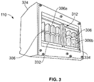
- FIG 3 illustrates a perspective view of a first side (such as a bottom or top) of a UV lamp 110, according to an example of the present disclosure.
- the UV lamp 110 includes a housing 324 that retains a plurality of UV light emitters 306 that are configured to emit UV light through an aperture 312.
- the UV lamp 110 includes a first plurality of UV light emitters 306a and a second plurality of UV light emitters 306b.
- the first plurality of UV light emitters 306a are contained within a first sub-housing 332
- the second plurality of UV light emitters 306b are contained within a second sub-housing 334 that is distinct from the first sub-housing 332.
- Each of the first sub-housing 332 and the second sub-housing 334 can contain more or less UV light emitters 306 than shown.
- the UV lamp 110 can include a single sub-housing that retains all of the UV light emitters 306.
- the UV lamp 110 can include a single UV light emitter 306, instead a plurality of UV light emitters 306.
- the UV lamp 110 shown in Figure 3 is merely an example.
- the UV lamp 110 can be sized and shaped differently than shown in Figure 3 .
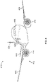
- Figure 4 illustrates a perspective front view of an aircraft 410, according to an example of the present disclosure.
- the aircraft 410 includes a propulsion system 412 that includes engines 414, for example.
- the propulsion system 412 may include more engines 414 than shown.
- the engines 414 are carried by wings 416 of the aircraft 410.
- the engines 414 may be carried by a fuselage 418 and/or an empennage 420.
- the empennage 420 may also support horizontal stabilizers 422 and a vertical stabilizer 424.
- the fuselage 418 of the aircraft 410 defines an internal cabin 430, which includes a flight deck or cockpit, one or more work sections (for example, galleys, personnel carry-on baggage areas, and the like), one or more passenger sections (for example, first class, business class, and coach sections), one or more lavatories, and/or the like.
- the internal cabin 430 is an example of the environment, such as the internal cabin 104 shown in Figure 1 .
- Examples of the present disclosure are used within the internal cabin 430.
- examples of the present disclosure may be used with various other vehicles, such as automobiles, buses, locomotives and train cars, watercraft, and the like.
- examples of the present disclosure may be used with respect to fixed structures, such as commercial and residential buildings.
- FIG. 5A illustrates a top plan view of an internal cabin 430 of an aircraft, according to an example of the present disclosure.
- the internal cabin 430 may be within the fuselage 432 of the aircraft, such as the fuselage 418 of Figure 4 .
- one or more fuselage walls may define the internal cabin 430.
- the internal cabin 430 includes multiple sections, including a front section 433, a first class section 434, a business class section 436, a front galley station 438, an expanded economy or coach section 440, a standard economy of coach section 442, and an aft section 444, which may include multiple lavatories and galley stations.
- the internal cabin 430 may include more or less sections than shown.
- the internal cabin 430 may not include a first class section, and may include more or less galley stations than shown.
- Each of the sections may be separated by a cabin transition area 446, which may include class divider assemblies between aisles 448.
- the internal cabin 430 includes two aisles 450 and 452 that lead to the aft section 444.
- the internal cabin 430 may have less or more aisles than shown.
- the internal cabin 430 may include a single aisle that extends through the center of the internal cabin 430 that leads to the aft section 444.
- the aisles 448, 450, and 452 extend to egress paths or door passageways 460. Exit doors 462 are located at ends of the egress paths 460.
- the egress paths 460 may be perpendicular to the aisles 448, 450, and 452.
- the internal cabin 430 may include more egress paths 460 at different locations than shown. Examples of the present disclosure shown and described with respect to Figures 1-2 may be used within the internal cabin 430.
- Figure 5B illustrates a top plan view of an internal cabin 480 of an aircraft, according to an example of the present disclosure.
- the internal cabin 480 is an example of the internal cabin 430 shown in Figure 4 .
- the internal cabin 480 may be within a fuselage 481 of the aircraft.
- one or more fuselage walls may define the internal cabin 480.
- the internal cabin 480 includes multiple sections, including a main cabin 482 having passenger seats 483, and an aft section 485 behind the main cabin 482. It is to be understood that the internal cabin 480 may include more or less sections than shown.
- the internal cabin 480 may include a single aisle 484 that leads to the aft section 485.
- the single aisle 484 may extend through the center of the internal cabin 480 that leads to the aft section 485.
- the single aisle 484 may be coaxially aligned with a central longitudinal plane of the internal cabin 480.
- the aisle 484 extends to an egress path or door passageway 490. Exit doors 492 are located at ends of the egress path 490.
- the egress path 490 may be perpendicular to the aisle 484.
- the internal cabin 480 may include more egress paths than shown. Examples of the present disclosure shown and described with respect to Figures 1-2 may be used within the internal cabin 480.
- Figure 6 illustrates a perspective interior view of an internal cabin 500 of an aircraft, according to an example of the present disclosure.
- the internal cabin 500 includes outboard walls 502 connected to a ceiling 504. Windows 506 may be formed within the outboard walls 502.
- a floor 508 supports rows of seats 510. As shown in Figure 10, a row 512 may include two seats 510 on either side of an aisle 513. However, the row 512 may include more or less seats 510 than shown. Additionally, the internal cabin 500 may include more aisles than shown.
- PSUs 514 are secured between an outboard wall 502 and the ceiling 504 on either side of the aisle 513.
- the PSUs 514 extend between a front end and rear end of the internal cabin 500.
- a PSU 514 may be positioned over each seat 510 within a row 512.
- Each PSU 514 may include a housing 516 that generally contains vents, reading lights, an oxygen bag drop panel, an attendant request button, and other such controls over each seat 510 (or groups of seats) within a row 512.
- Overhead stowage bin assemblies 518 are secured to the ceiling 504 and/or the outboard wall 502 above and inboard from the PSU 514 on either side of the aisle 513.
- the overhead stowage bin assemblies 518 are secured over the seats 510.
- the overhead stowage bin assemblies 518 extend between the front and rear end of the internal cabin 500.
- Each stowage bin assembly 518 may include a pivot bin or bucket 520 pivotally secured to a strongback (hidden from view in Figure 6 ).
- the overhead stowage bin assemblies 518 may be positioned above and inboard from lower surfaces of the PSUs 514.
- the overhead stowage bin assemblies 518 are configured to be pivoted open in order to receive passenger carry-on baggage and personal items, for example.
- the internal cabin 500 is an example of an environment, such as the internal cabin 104 shown in Figure 1 .
- examples of the present disclosure provide systems and methods for managing power among UV lamps and other powered sub-systems of a vehicle. Further, examples of the present disclosure provide systems and methods for efficiently and effectively apportioning power to various powered sub-systems and UV lamps of a vehicle.
- a structure, limitation, or element that is "configured to” perform a task or operation is particularly structurally formed, constructed, or adapted in a manner corresponding to the task or operation.
- an object that is merely capable of being modified to perform the task or operation is not “configured to” perform the task or operation as used herein.
Landscapes
- Engineering & Computer Science (AREA)
- Health & Medical Sciences (AREA)
- Aviation & Aerospace Engineering (AREA)
- Power Engineering (AREA)
- Public Health (AREA)
- Veterinary Medicine (AREA)
- Epidemiology (AREA)
- Life Sciences & Earth Sciences (AREA)
- Animal Behavior & Ethology (AREA)
- General Health & Medical Sciences (AREA)
- Computer Vision & Pattern Recognition (AREA)
- Manufacturing & Machinery (AREA)
- Artificial Intelligence (AREA)
- Transportation (AREA)
- Evolutionary Computation (AREA)
- Medical Informatics (AREA)
- Software Systems (AREA)
- Physics & Mathematics (AREA)
- General Physics & Mathematics (AREA)
- Automation & Control Theory (AREA)
- Circuit Arrangement For Electric Light Sources In General (AREA)
- Apparatus For Disinfection Or Sterilisation (AREA)
- Arrangements Of Lighting Devices For Vehicle Interiors, Mounting And Supporting Thereof, Circuits Therefore (AREA)
Applications Claiming Priority (1)
| Application Number | Priority Date | Filing Date | Title |
|---|---|---|---|
| US202163186839P | 2021-05-11 | 2021-05-11 |
Publications (2)
| Publication Number | Publication Date |
|---|---|
| EP4089014A1 true EP4089014A1 (fr) | 2022-11-16 |
| EP4089014B1 EP4089014B1 (fr) | 2025-09-10 |
Family
ID=81585759
Family Applications (1)
| Application Number | Title | Priority Date | Filing Date |
|---|---|---|---|
| EP22172170.7A Active EP4089014B1 (fr) | 2021-05-11 | 2022-05-06 | Systèmes et procédés de gestion et de prédiction de la consommation d'énergie pour des lampes ultraviolettes dans un environnement |
Country Status (4)
| Country | Link |
|---|---|
| US (1) | US12311083B2 (fr) |
| EP (1) | EP4089014B1 (fr) |
| JP (1) | JP2022174733A (fr) |
| CN (1) | CN115333229A (fr) |
Citations (4)
| Publication number | Priority date | Publication date | Assignee | Title |
|---|---|---|---|---|
| EP3315142A1 (fr) * | 2015-06-26 | 2018-05-02 | Seoul Viosys Co. Ltd. | Appareil de stérilisation |
| US20180371733A1 (en) * | 2017-06-26 | 2018-12-27 | The Boeing Company | Disinfection Systems and Methods for Operating a Light System |
| US20190030195A1 (en) * | 2017-07-28 | 2019-01-31 | Airbus Sas | Aircraft cabin disinfection system |
| EP3659919A1 (fr) * | 2018-11-28 | 2020-06-03 | The Boeing Company | Systèmes et procédés de détection d'occupation de toilettes |
Family Cites Families (2)
| Publication number | Priority date | Publication date | Assignee | Title |
|---|---|---|---|---|
| JP6706877B2 (ja) * | 2012-09-12 | 2020-06-10 | ザ・ボーイング・カンパニーThe Boeing Company | 電力管理制御システム |
| US10130727B1 (en) | 2017-06-26 | 2018-11-20 | The Boeing Company | Systems and methods for operating a light system |
-
2022
- 2022-03-24 US US17/703,186 patent/US12311083B2/en active Active
- 2022-05-06 EP EP22172170.7A patent/EP4089014B1/fr active Active
- 2022-05-10 JP JP2022077366A patent/JP2022174733A/ja active Pending
- 2022-05-10 CN CN202210503355.7A patent/CN115333229A/zh active Pending
Patent Citations (4)
| Publication number | Priority date | Publication date | Assignee | Title |
|---|---|---|---|---|
| EP3315142A1 (fr) * | 2015-06-26 | 2018-05-02 | Seoul Viosys Co. Ltd. | Appareil de stérilisation |
| US20180371733A1 (en) * | 2017-06-26 | 2018-12-27 | The Boeing Company | Disinfection Systems and Methods for Operating a Light System |
| US20190030195A1 (en) * | 2017-07-28 | 2019-01-31 | Airbus Sas | Aircraft cabin disinfection system |
| EP3659919A1 (fr) * | 2018-11-28 | 2020-06-03 | The Boeing Company | Systèmes et procédés de détection d'occupation de toilettes |
Also Published As
| Publication number | Publication date |
|---|---|
| US20220362434A1 (en) | 2022-11-17 |
| JP2022174733A (ja) | 2022-11-24 |
| EP4089014B1 (fr) | 2025-09-10 |
| CN115333229A (zh) | 2022-11-11 |
| US12311083B2 (en) | 2025-05-27 |
Similar Documents
| Publication | Publication Date | Title |
|---|---|---|
| EP2572985B1 (fr) | Procédé et système pour l'embarquement dual d'aéronefs | |
| US10672208B2 (en) | Touch-free operable stowage bin assemblies | |
| US10906458B2 (en) | Vehicles including electronic stowage bin control systems | |
| US10793277B2 (en) | Electronic stowage bin control systems and methods | |
| Schultz et al. | Boarding on the critical path of the turnaround | |
| US10647429B2 (en) | Vehicle stowage bin assemblies having weight sensors | |
| Zhu et al. | Cooperative scheduling optimization for ground-handling vehicles by considering flights’ uncertainty | |
| US10864849B2 (en) | Illuminated stowage bin assemblies within vehicles | |
| US10822087B2 (en) | Carpet display systems and methods | |
| ZA200410375B (en) | Method of allocating seats to customers in a computer reservation system | |
| US20180374019A1 (en) | Flight schedule determining systems and methods | |
| EP4101475A1 (fr) | Systèmes et procédés de désinfection des parties d'un espace clos et d'attribution de ressources de désinfection dans l'espace clos | |
| Fricke et al. | Improving aircraft turn around reliability | |
| CN119831200A (zh) | 一种停机位分配方法及装置 | |
| US12311083B2 (en) | Systems and methods for managing and predicting power usage for ultraviolet lamps within an environment | |
| JP2013086794A (ja) | 自己構成型客室管理システム | |
| CN114444826B (zh) | 货运航班停机位的分配方法、装置、设备和可读存储介质 | |
| CN117575260A (zh) | 一种在机场自动生成航班保障任务计划的方法及系统 | |
| BR102018004695B1 (pt) | Sistema de controle de compartimento de armazenamento para um veículo, veículo e método para operar um sistema de controle de compartimento de armazenamento |
Legal Events
| Date | Code | Title | Description |
|---|---|---|---|
| PUAI | Public reference made under article 153(3) epc to a published international application that has entered the european phase |
Free format text: ORIGINAL CODE: 0009012 |
|
| STAA | Information on the status of an ep patent application or granted ep patent |
Free format text: STATUS: THE APPLICATION HAS BEEN PUBLISHED |
|
| AK | Designated contracting states |
Kind code of ref document: A1 Designated state(s): AL AT BE BG CH CY CZ DE DK EE ES FI FR GB GR HR HU IE IS IT LI LT LU LV MC MK MT NL NO PL PT RO RS SE SI SK SM TR |
|
| RAP3 | Party data changed (applicant data changed or rights of an application transferred) |
Owner name: THE BOEING COMPANY |
|
| STAA | Information on the status of an ep patent application or granted ep patent |
Free format text: STATUS: REQUEST FOR EXAMINATION WAS MADE |
|
| 17P | Request for examination filed |
Effective date: 20230516 |
|
| RBV | Designated contracting states (corrected) |
Designated state(s): AL AT BE BG CH CY CZ DE DK EE ES FI FR GB GR HR HU IE IS IT LI LT LU LV MC MK MT NL NO PL PT RO RS SE SI SK SM TR |
|
| STAA | Information on the status of an ep patent application or granted ep patent |
Free format text: STATUS: EXAMINATION IS IN PROGRESS |
|
| 17Q | First examination report despatched |
Effective date: 20240304 |
|
| GRAP | Despatch of communication of intention to grant a patent |
Free format text: ORIGINAL CODE: EPIDOSNIGR1 |
|
| STAA | Information on the status of an ep patent application or granted ep patent |
Free format text: STATUS: GRANT OF PATENT IS INTENDED |
|
| INTG | Intention to grant announced |
Effective date: 20250415 |
|
| RIN1 | Information on inventor provided before grant (corrected) |
Inventor name: KING, TERESA A. Inventor name: CALLAHAN, KEVIN S. Inventor name: CHILDRESS, JAMIE J. |
|
| GRAS | Grant fee paid |
Free format text: ORIGINAL CODE: EPIDOSNIGR3 |
|
| GRAA | (expected) grant |
Free format text: ORIGINAL CODE: 0009210 |
|
| STAA | Information on the status of an ep patent application or granted ep patent |
Free format text: STATUS: THE PATENT HAS BEEN GRANTED |
|
| P01 | Opt-out of the competence of the unified patent court (upc) registered |
Free format text: CASE NUMBER: UPC_APP_0428_4089014/2025 Effective date: 20250716 |
|
| AK | Designated contracting states |
Kind code of ref document: B1 Designated state(s): AL AT BE BG CH CY CZ DE DK EE ES FI FR GB GR HR HU IE IS IT LI LT LU LV MC MK MT NL NO PL PT RO RS SE SI SK SM TR |
|
| REG | Reference to a national code |
Ref country code: GB Ref legal event code: FG4D |
|
| REG | Reference to a national code |
Ref country code: CH Ref legal event code: EP |
|
| REG | Reference to a national code |
Ref country code: DE Ref legal event code: R096 Ref document number: 602022021037 Country of ref document: DE |
|
| REG | Reference to a national code |
Ref country code: IE Ref legal event code: FG4D |
|
| PG25 | Lapsed in a contracting state [announced via postgrant information from national office to epo] |
Ref country code: NO Free format text: LAPSE BECAUSE OF FAILURE TO SUBMIT A TRANSLATION OF THE DESCRIPTION OR TO PAY THE FEE WITHIN THE PRESCRIBED TIME-LIMIT Effective date: 20251210 |
|
| REG | Reference to a national code |
Ref country code: LT Ref legal event code: MG9D |
|
| PG25 | Lapsed in a contracting state [announced via postgrant information from national office to epo] |
Ref country code: FI Free format text: LAPSE BECAUSE OF FAILURE TO SUBMIT A TRANSLATION OF THE DESCRIPTION OR TO PAY THE FEE WITHIN THE PRESCRIBED TIME-LIMIT Effective date: 20250910 |
|
| REG | Reference to a national code |
Ref country code: NL Ref legal event code: MP Effective date: 20250910 |
|
| PG25 | Lapsed in a contracting state [announced via postgrant information from national office to epo] |
Ref country code: HR Free format text: LAPSE BECAUSE OF FAILURE TO SUBMIT A TRANSLATION OF THE DESCRIPTION OR TO PAY THE FEE WITHIN THE PRESCRIBED TIME-LIMIT Effective date: 20250910 |
|
| PG25 | Lapsed in a contracting state [announced via postgrant information from national office to epo] |
Ref country code: GR Free format text: LAPSE BECAUSE OF FAILURE TO SUBMIT A TRANSLATION OF THE DESCRIPTION OR TO PAY THE FEE WITHIN THE PRESCRIBED TIME-LIMIT Effective date: 20251211 |
|
| PG25 | Lapsed in a contracting state [announced via postgrant information from national office to epo] |
Ref country code: SE Free format text: LAPSE BECAUSE OF FAILURE TO SUBMIT A TRANSLATION OF THE DESCRIPTION OR TO PAY THE FEE WITHIN THE PRESCRIBED TIME-LIMIT Effective date: 20250910 |
|
| PG25 | Lapsed in a contracting state [announced via postgrant information from national office to epo] |
Ref country code: LV Free format text: LAPSE BECAUSE OF FAILURE TO SUBMIT A TRANSLATION OF THE DESCRIPTION OR TO PAY THE FEE WITHIN THE PRESCRIBED TIME-LIMIT Effective date: 20250910 |
|
| PG25 | Lapsed in a contracting state [announced via postgrant information from national office to epo] |
Ref country code: PL Free format text: LAPSE BECAUSE OF FAILURE TO SUBMIT A TRANSLATION OF THE DESCRIPTION OR TO PAY THE FEE WITHIN THE PRESCRIBED TIME-LIMIT Effective date: 20250910 Ref country code: BG Free format text: LAPSE BECAUSE OF FAILURE TO SUBMIT A TRANSLATION OF THE DESCRIPTION OR TO PAY THE FEE WITHIN THE PRESCRIBED TIME-LIMIT Effective date: 20250910 |
|
| PG25 | Lapsed in a contracting state [announced via postgrant information from national office to epo] |
Ref country code: RS Free format text: LAPSE BECAUSE OF FAILURE TO SUBMIT A TRANSLATION OF THE DESCRIPTION OR TO PAY THE FEE WITHIN THE PRESCRIBED TIME-LIMIT Effective date: 20251210 |
|
| PG25 | Lapsed in a contracting state [announced via postgrant information from national office to epo] |
Ref country code: ES Free format text: LAPSE BECAUSE OF FAILURE TO SUBMIT A TRANSLATION OF THE DESCRIPTION OR TO PAY THE FEE WITHIN THE PRESCRIBED TIME-LIMIT Effective date: 20250910 |
|
| REG | Reference to a national code |
Ref country code: AT Ref legal event code: MK05 Ref document number: 1835666 Country of ref document: AT Kind code of ref document: T Effective date: 20250910 |
|
| PG25 | Lapsed in a contracting state [announced via postgrant information from national office to epo] |
Ref country code: NL Free format text: LAPSE BECAUSE OF FAILURE TO SUBMIT A TRANSLATION OF THE DESCRIPTION OR TO PAY THE FEE WITHIN THE PRESCRIBED TIME-LIMIT Effective date: 20250910 |
|
| PG25 | Lapsed in a contracting state [announced via postgrant information from national office to epo] |
Ref country code: SM Free format text: LAPSE BECAUSE OF FAILURE TO SUBMIT A TRANSLATION OF THE DESCRIPTION OR TO PAY THE FEE WITHIN THE PRESCRIBED TIME-LIMIT Effective date: 20250910 |
|
| PG25 | Lapsed in a contracting state [announced via postgrant information from national office to epo] |
Ref country code: AT Free format text: LAPSE BECAUSE OF FAILURE TO SUBMIT A TRANSLATION OF THE DESCRIPTION OR TO PAY THE FEE WITHIN THE PRESCRIBED TIME-LIMIT Effective date: 20250910 |
|
| PG25 | Lapsed in a contracting state [announced via postgrant information from national office to epo] |
Ref country code: IT Free format text: LAPSE BECAUSE OF FAILURE TO SUBMIT A TRANSLATION OF THE DESCRIPTION OR TO PAY THE FEE WITHIN THE PRESCRIBED TIME-LIMIT Effective date: 20250910 |
|
| PG25 | Lapsed in a contracting state [announced via postgrant information from national office to epo] |
Ref country code: IS Free format text: LAPSE BECAUSE OF FAILURE TO SUBMIT A TRANSLATION OF THE DESCRIPTION OR TO PAY THE FEE WITHIN THE PRESCRIBED TIME-LIMIT Effective date: 20260110 |
|
| PG25 | Lapsed in a contracting state [announced via postgrant information from national office to epo] |
Ref country code: CZ Free format text: LAPSE BECAUSE OF FAILURE TO SUBMIT A TRANSLATION OF THE DESCRIPTION OR TO PAY THE FEE WITHIN THE PRESCRIBED TIME-LIMIT Effective date: 20250910 Ref country code: PT Free format text: LAPSE BECAUSE OF FAILURE TO SUBMIT A TRANSLATION OF THE DESCRIPTION OR TO PAY THE FEE WITHIN THE PRESCRIBED TIME-LIMIT Effective date: 20260112 |
|
| PG25 | Lapsed in a contracting state [announced via postgrant information from national office to epo] |
Ref country code: SK Free format text: LAPSE BECAUSE OF FAILURE TO SUBMIT A TRANSLATION OF THE DESCRIPTION OR TO PAY THE FEE WITHIN THE PRESCRIBED TIME-LIMIT Effective date: 20250910 Ref country code: EE Free format text: LAPSE BECAUSE OF FAILURE TO SUBMIT A TRANSLATION OF THE DESCRIPTION OR TO PAY THE FEE WITHIN THE PRESCRIBED TIME-LIMIT Effective date: 20250910 |