EP4089016B1 - Avions avec systèmes d'humidification et procédés pour humidifier un intérieur d'avion - Google Patents
Avions avec systèmes d'humidification et procédés pour humidifier un intérieur d'avion Download PDFInfo
- Publication number
- EP4089016B1 EP4089016B1 EP22172395.0A EP22172395A EP4089016B1 EP 4089016 B1 EP4089016 B1 EP 4089016B1 EP 22172395 A EP22172395 A EP 22172395A EP 4089016 B1 EP4089016 B1 EP 4089016B1
- Authority
- EP
- European Patent Office
- Prior art keywords
- air
- interior
- vehicle
- water
- air stream
- Prior art date
- Legal status (The legal status is an assumption and is not a legal conclusion. Google has not performed a legal analysis and makes no representation as to the accuracy of the status listed.)
- Active
Links
Images


Classifications
-
- B—PERFORMING OPERATIONS; TRANSPORTING
- B64—AIRCRAFT; AVIATION; COSMONAUTICS
- B64D—EQUIPMENT FOR FITTING IN OR TO AIRCRAFT; FLIGHT SUITS; PARACHUTES; ARRANGEMENT OR MOUNTING OF POWER PLANTS OR PROPULSION TRANSMISSIONS IN AIRCRAFT
- B64D13/00—Arrangements or adaptations of air-treatment apparatus for aircraft crew or passengers, or freight space
- B64D13/06—Arrangements or adaptations of air-treatment apparatus for aircraft crew or passengers, or freight space the air being conditioned
-
- B—PERFORMING OPERATIONS; TRANSPORTING
- B64—AIRCRAFT; AVIATION; COSMONAUTICS
- B64D—EQUIPMENT FOR FITTING IN OR TO AIRCRAFT; FLIGHT SUITS; PARACHUTES; ARRANGEMENT OR MOUNTING OF POWER PLANTS OR PROPULSION TRANSMISSIONS IN AIRCRAFT
- B64D13/00—Arrangements or adaptations of air-treatment apparatus for aircraft crew or passengers, or freight space
- B64D13/06—Arrangements or adaptations of air-treatment apparatus for aircraft crew or passengers, or freight space the air being conditioned
- B64D13/08—Arrangements or adaptations of air-treatment apparatus for aircraft crew or passengers, or freight space the air being conditioned the air being heated or cooled
-
- F—MECHANICAL ENGINEERING; LIGHTING; HEATING; WEAPONS; BLASTING
- F02—COMBUSTION ENGINES; HOT-GAS OR COMBUSTION-PRODUCT ENGINE PLANTS
- F02C—GAS-TURBINE PLANTS; AIR INTAKES FOR JET-PROPULSION PLANTS; CONTROLLING FUEL SUPPLY IN AIR-BREATHING JET-PROPULSION PLANTS
- F02C6/00—Plural gas-turbine plants; Combinations of gas-turbine plants with other apparatus; Adaptations of gas-turbine plants for special use
- F02C6/04—Gas-turbine plants providing heated or pressurised working fluid for other apparatus, e.g. without mechanical power output
- F02C6/06—Gas-turbine plants providing heated or pressurised working fluid for other apparatus, e.g. without mechanical power output providing compressed gas
- F02C6/08—Gas-turbine plants providing heated or pressurised working fluid for other apparatus, e.g. without mechanical power output providing compressed gas the gas being bled from the gas-turbine compressor
-
- B—PERFORMING OPERATIONS; TRANSPORTING
- B64—AIRCRAFT; AVIATION; COSMONAUTICS
- B64D—EQUIPMENT FOR FITTING IN OR TO AIRCRAFT; FLIGHT SUITS; PARACHUTES; ARRANGEMENT OR MOUNTING OF POWER PLANTS OR PROPULSION TRANSMISSIONS IN AIRCRAFT
- B64D13/00—Arrangements or adaptations of air-treatment apparatus for aircraft crew or passengers, or freight space
- B64D13/06—Arrangements or adaptations of air-treatment apparatus for aircraft crew or passengers, or freight space the air being conditioned
- B64D2013/0603—Environmental Control Systems
- B64D2013/0655—Environmental Control Systems with zone or personal climate controls
-
- B—PERFORMING OPERATIONS; TRANSPORTING
- B64—AIRCRAFT; AVIATION; COSMONAUTICS
- B64D—EQUIPMENT FOR FITTING IN OR TO AIRCRAFT; FLIGHT SUITS; PARACHUTES; ARRANGEMENT OR MOUNTING OF POWER PLANTS OR PROPULSION TRANSMISSIONS IN AIRCRAFT
- B64D13/00—Arrangements or adaptations of air-treatment apparatus for aircraft crew or passengers, or freight space
- B64D13/06—Arrangements or adaptations of air-treatment apparatus for aircraft crew or passengers, or freight space the air being conditioned
- B64D2013/0603—Environmental Control Systems
- B64D2013/0662—Environmental Control Systems with humidity control
Definitions
- the technical field relates generally to humidification systems for vehicles, and more particularly relates to humidification systems that recover water from the air of vehicle interiors and that humidify air supplied to the vehicle interiors with at least a portion of the recovered water.
- Vehicles such as aircraft generally utilize either a combination of recycled cabin air and exterior air, or exterior air exclusively to maintain cabin air quality when the aircraft is in operation.
- aircraft often maintain high altitudes for extended periods of time and collect exterior air from such ambient environments throughout a substantial portion of the flight.
- ambient air has substantially low moisture content.
- the moisture content of the cabin air becomes and/or remains relatively low.
- Low moisture content in cabin air increases the potential for viral spread and decreases the comfort level for passengers and crew aboard the aircraft.
- US 4 461 155 A discloses an aircraft cabin humidification system for humidifying an air mass within said cabin, said system comprising: replacement means for ventilating said cabin with a ram air stream; means for exhausting at least a portion of said air from said cabin; removal means for at least partially removing moisture from said air exhausted from said cabin; recycle means for recycling at least a portion of said moisture from said exhausted air; and humidification means for humidifying said cabin by adding at least a portion of said recycled moisture to said cabin.
- a vehicle a humidification system for a vehicle having an interior containing interior air, and a method for humidifying an interior of a vehicle are provided herein.
- a vehicle according to claim 1 is provided.
- the exemplary embodiments taught herein provide a vehicle, for example, an aircraft or the like.
- the vehicle includes a vehicle structure, such as, for example, an aircraft structure, fuselage, or the like, at least partially surrounding an interior containing interior air.
- the vehicle further includes a humidification system in fluid communication with a first air stream and the interior.
- the vehicle includes an engine that is coupled to the vehicle structure and the vehicle is configured to extract bleed air from the engine as extracted bleed air that forms at least a portion of the first air stream.
- the humidification system includes a humidifier that is configured to humidify the first air stream to form a humidified air stream. The humidified air stream is introduced into the interior.
- the humidification system further includes a water recovery zone that is in fluid communication with the interior to receive the interior air.
- zone refers to an area(s) including one or more equipment items and/or one or more sub-zones.
- Equipment items can include one or more heat exchangers, separators, reservoirs, tanks, vessels, heaters, coolers/chillers, pipes, ducts, pumps, compressors, valves, controllers, and the like. Additionally, an equipment item can further include one or more zones or sub-zones.
- the water recovery zone is configured to condense and separate water from the interior air.
- the humidifier is further configured to receive the condensed and separated water from the water recovery zone for humidifying the first air stream.
- the vehicle provides humidified air to the interior of the vehicle.
- a water recovery zone that is in fluid communication with the interior to receive the interior air and that is configured to condense and separate water from the interior air, water is recovered from the interior air.
- configuring the humidifier to receive the condensed and separated water to humidify the first air stream provides recycled utilization of the water, thereby reducing or eliminating the need for carrying additional water aboard the vehicle for humidifying the interior of the vehicle.
- the total water weight necessary for humidifying the interior is reduced or eliminated compared to other approaches, thereby saving weight and reducing fuel consumption to operate the vehicle.
- the humidity level of the interior air is improved (e.g., increased), thereby decreasing the potential for viral spread and increasing the comfort level for passengers and crew aboard the vehicle.
- FIG. 1 illustrates a schematic view of a vehicle 10 including an air conditioning system 12 with a humidification system 14 in accordance with an exemplary embodiment.
- the vehicle 10 includes a vehicle structure 16 at least partially surrounding an interior 18 of the vehicle 10 and containing interior air 20.
- the vehicle 10 is an aircraft and the vehicle structure 16 is an aircraft structure such as, for example, a fuselage.
- the interior 18 may include one or more interior areas 22 such as a cabin area, a lavatory area, a cockpit area, and/or the like.
- the vehicle 10 includes an engine 24 coupled to the vehicle structure 16 and in fluid communication with the air conditioning system 12. As illustrated, the vehicle 10 includes a singular engine 24, but it is to be understood that various alternate embodiments of the vehicle 10 include a plurality of engines such as two, three, or more engines.
- the engine 24 is, for example, a turbine engine such as, for example, a turbofan engine.
- the engine 24 includes one or more compressors 26 and takes in ambient air 28 and pressurizes and combusts at least a portion of the ambient air 28 with fuel in a burner to drive one or more turbines to produce thrust 30 that propels the vehicle 10 in a general forward direction 32.
- bleed air is extracted from the engine 24 via line 34 and/or line 42 and fluidly communicated to the air conditioning system 12 via lines 36, 38, and 39.
- the bleed air may be extracted from any of various compressor stage ports of the compressor(s) 26 of the engine 24.
- bleed air extracted via line 34 corresponds to a lower compressor stage while bleed air extracted via line 42 corresponds to a higher compressor stage.
- the bleed air is at increased pressure and temperature compared to the ambient air 28.
- Bleed air extracted via line 42 and/or bleed air extracted via line 34 is routed to a heat exchanger 46 via line 36.
- a control valve 48 regulates the pressure of bleed air to the heat exchanger 46 via line 36.
- the regulated pressure from the control valve 48 to line 36 is in the range of 241-414 kPa (35-60 psig).
- the heat exchanger 46 may be operably coupled to a control valve 54 that regulates the flow rate of engine fan air through the heat exchanger 46 with the exchanged fan air being exhausted overboard. Additionally, and in accordance with an exemplary embodiment, the heat exchanger 46 may include additional valves, controls, and or sensors to assist in regulating the temperature and pressure of the extracted bleed air for fluid communication to the air conditioning system 12.
- the environmental control system 56 includes an ozone converter, heat exchanger(s), control valve(s), control sensor(s), and/or refrigeration cycle(s) that are cooperatively configured to purify, cool and depressurize the extracted bleed air advanced to the environmental control system 56 via line 38 to form purified, cooled, depressurized air that is passed along to the manifold 60 via line 68.
- the purified, cooled, depressurized air advanced to the manifold 60 via line 68 is purified, cooled, and depressurized by the environmental control system 56 to a temperature of from about -4.4°C (24°F) to about 2.8°C (37°F) and to a pressure of about 103.4 kPa (15 psia) provided to the manifold 60.
- the environmental control system 56 is configured to receive ambient air 28 via line 70 for cooling and/or depressurizing the extracted bleed air. The ambient air 28 advanced to the environmental control system 56 via line 70 is then exhausted back out of the vehicle 10 via line 72.
- the vehicle 10 further includes a vehicle exhaust duct 64 that is disposed in the interior 18 and that is configured to receive a portion of the interior air 20 from the interior 18.
- the vehicle exhaust duct 64 is in fluid communication with the valve 66 via lines 90 and 92.
- the valve 66 is in fluid communication with the interior 18 through the exhaust duct 64.
- the valve 66 is configured to exhaust a portion of the interior air 20 out of the vehicle, for example, to control pressure of the interior air 20 remaining in the interior 18.
- the heat exchanger 96 is further configured to receive ambient air 28 via line 104 for cooling the portion of the interior air 20 supplied to the heat exchanger via line 94.
- the portion of the interior air 20 supplied to the heat exchanger 96 via line 94 is cooled by indirect heat exchange with the ambient air 20 supplied to the heat exchanger 96 via line 94.
- line 104 includes a control valve 106 that regulates the flow rate of ambient air 20 fluidly communicated to the heat exchanger 96 for cooling.
- the heat exchanger 96 is in fluid communication with the valve 66 via line 108 and the valve 66 is configured to exhaust the ambient air 20 back out of the vehicle 10 after indirect heat exchange with the portion of the interior air 20 communicated to the heat exchanger 96 via line 94.
- the heat exchanger 96 is also in fluid communication with the water separator 98 to supply the water separator 98 with the cooled air stream via line 110.
- the water separator 98 is configured to receive the cooled air stream via line 110 and condense and separate water from the cooled air stream and form a cooled, dehumidified air stream.
- the water separator 98 is a centrifugal water separator or the like.
- the water condensed and separated from the cooled air stream is fluidly communicated to the water reservoir 100 via line 112 and the cooled, dehumidified air stream is fluidly communicated to the valve 66 via line 114.
- the valve 66 exhausts the cooled, dehumidified air stream back out of the vehicle 10.
- the water reservoir 100 is configured to receive the condensed and separated water from the water separator 98 via line 112. Additionally, the water reservoir 100 is configured to hold the condensed and separated water and, optionally, to hold additional water if needed.
- the water reservoir 100 includes an ultraviolet (UV) light source that is configured to generate UV light for treating the water in the water reservoir 100.
- the UV light source may be disposed adjacent to and/or in direct contact with the water in the water reservoir 100 and/or in line 83 for treating the water in the water reservoir 100.
- the UV light acts as a disinfection treatment that kills and/or inactivates microorganisms that may be present in the water prior to delivery to pump 102.
- the water reservoir 100 is in fluid communication with the pump 102 via line 116 to provide water to the pump 102.
- the pump 102 advances water to the humidifier 82 via line 118.
- the pump 102 provides the humidifier 82 with pressurized water for forming the humidified air stream discussed above.
- a vehicle 210 is similar configured to the vehicle 10 including an air conditioning system 212 with a humidification system 14 but with the exception that the vehicle 210 has multiple engines 24 and 224.
- the engine 224 is similarly configured to the engine 24 discussed above and bleed air is extracted from the engine 224 either via line 234 or via line 242 and is advanced to the vehicle 210 and air conditioning system via lines 236, 238, and 239.
- a check valve 240 moderates the flow of the extracted bleed air when extracted via line 234 and a control valve 244 moderates the flow of the extracted bleed air when extracted via line 242.
- the check valve 240 also prevents reverse flow between the higher compressor stage and the lower compressor stage.
- bleed air from the higher compressor stage may be routed from the engine 224 via line 242 that includes the control valve 244 for regulating the flow rate of bleed air from the engine 224 for operating cases where lower stage extraction via line 234 would be insufficient for bleed air system demand.
- Bleed air extracted via line 242 and/or bleed air extracted via line 234 is routed to a heat exchanger 246 via line 236.
- a control valve 48 regulates the pressure of bleed air to the heat exchanger 246 via line 236.
- the regulated pressure from the control valve 248 to line 236 is in the range of 241-414 kPa (35-60 psig).
- the heat exchanger 246 is a single pass cross flow heat exchanger 246.
- the heat exchanger 246 provides the air conditioning system 212 with the extracted bleed air at a regulated temperature.
- the extracted bleed air communicated via line 236 to the heat exchanger 246 is cooled by the heat exchanger 246 to a temperature of about 204.4°C (400°F) and a pressure of about 275.8-414 kPa (40-60 psig) and is then communicated to the air conditioning system via line 238.
- the engine 224 includes a fan 250 and engine fan air is extracted via line 252 and fluidly communicated to the heat exchanger 246 for cooling the extracted bleed air.
- the heat exchanger may further include a control valve 254 that regulates the flow rate of engine fan air through the heat exchanger 246. Fan air from control valve 254 is then exhausted out of the vehicle 210 to the ambient environment. Additionally, and in accordance with an exemplary embodiment, the heat exchanger may include additional valves, controls, and or sensors to assist in regulating the temperature and pressure of the extracted bleed air for fluid communication to the air conditioning system 212.
- the air conditioning system 212 is similarly configured to the air conditioning system 12 but with the exception that the air conditioning system 212 further includes an additional environmental control system 256.
- the extracted bleed air is fluidly communicated from the engine 224 to the air conditioning system via lines 234, 236, 238, and 239.
- a portion of the extracted bleed air communicated from the heat exchanger 246 via line 238 is received by the environmental control system 256 and another portion of the extracted bleed air communicated from the heat exchanger 246 is received by the manifold 58 via line 239.
- the environmental control system 256 includes an ozone converter, heat exchanger(s), control valve(s), control sensor(s), and/or refrigeration cycle(s) that are cooperatively configured to purify, cool and depressurize the extracted bleed air communicated to the environmental control system 256 via line 238 to form purified, cooled, depressurized air that is communicated to the manifold 60 via line 268.
- the purified cooled, depressurized air communicated to the manifold 60 via line 268 is cooled and depressurized by the environmental control system 256 to a temperature of from about -4.4°C (24°F) to about 2.8 °C (37°F) and to a pressure of about 103.4 kPa (15 psia).
- the environmental control system 256 is configured to receive ambient air 28 via line 270 for cooling the extracted bleed air. The ambient air 28 communicated to the environmental control system 256 via line 270 is then exhausted back out of the vehicle 210 via line 272.
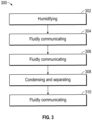
- a method 300 for humidifying an interior of a vehicle in accordance with an exemplary embodiment includes humidifying (STEP 302) a first air stream with a humidifier to form a humidified air stream.
- the humidified air stream is fluidly communicated (STEP 304) to interior of the vehicle.
- the interior air is fluidly communicated (STEP 306) to a water recovery zone.
- Water is condensed and separated (STEP 308) from the interior air with the water recovery zone.
- the water is fluidly communicated (STEP 310) from the water recovery zone to the humidifier.
Landscapes
- Engineering & Computer Science (AREA)
- Health & Medical Sciences (AREA)
- General Health & Medical Sciences (AREA)
- Pulmonology (AREA)
- Aviation & Aerospace Engineering (AREA)
- Chemical & Material Sciences (AREA)
- Combustion & Propulsion (AREA)
- Mechanical Engineering (AREA)
- General Engineering & Computer Science (AREA)
- Air-Conditioning For Vehicles (AREA)
- Air Humidification (AREA)
Claims (12)
- Véhicule (10) comprenant :une structure de véhicule (16) entourant au moins partiellement un intérieur (18), l'intérieur contenant de l'air intérieur (20) ; et,un système d'humidification (14) configuré pour être en communication fluidique avec un premier flux d'air et l'intérieur (18), le système d'humidification comprenant :un humidificateur (82) configuré pour humidifier le premier flux d'air afin de former un flux d'air humidifié qui est en communication fluidique avec l'intérieur ; etune zone de récupération d'eau (83) configurée pour recevoir l'air intérieur et pour condenser et séparer l'eau de l'air intérieur, la zone de récupération d'eau étant configurée pour être en communication fluidique avec l'humidificateur et pour fournir l'eau à l'humidificateur,ledit véhicule comprenant en outre une soupape (66) qui est en communication fluidique avec l'intérieur et qui est configurée pour évacuer une première partie de l'air intérieur hors du véhicule afin de réguler la pression de l'air intérieur restant dans l'intérieur ;et la zone de récupération d'eau (83) comprenant un échangeur de chaleur (96) configuré pour recevoir l'air intérieur et l'air ambiant de l'extérieur du véhicule, l'échangeur de chaleur étant en outre configuré pour refroidir une seconde partie de l'air intérieur afin de former un flux d'air refroidi par échange de chaleur indirect entre la seconde partie de l'air intérieur et l'air ambiant.
- Véhicule selon la revendication 1, dans lequel la soupape (66) est en communication fluidique avec l'échangeur de chaleur (96) pour évacuer l'air ambiant hors du véhicule après échange indirect de chaleur avec l'air intérieur.
- Véhicule selon la revendication 2, dans lequel la zone de récupération d'eau (83) comprend en outre un séparateur d'eau (98) configuré pour recevoir le flux d'air refroidi et condenser et séparer l'eau du flux d'air refroidi et former un flux d'air refroidi déshumidifié.
- Véhicule selon la revendication 3, dans lequel la soupape (66) est en communication fluidique avec le séparateur d'eau (98) pour recevoir le flux d'air refroidi et déshumidifié et est configurée pour évacuer le flux d'air refroidi et déshumidifié hors du véhicule.
- Véhicule selon la revendication 3 ou la revendication 4, dans lequel la zone de récupération d'eau (83) comprend en outre un réservoir d'eau (100) qui est en communication fluidique avec le séparateur d'eau (98) et avec l'humidificateur (82), le réservoir d'eau étant configuré pour recevoir l'eau provenant du séparateur d'eau et pour retenir l'eau.
- Véhicule selon la revendication 5, dans lequel le réservoir d'eau (100) comprend en outre une source de lumière ultraviolette (UV) qui est configurée pour générer une lumière ultraviolette pour traiter l'eau qui est communiquée au réservoir d'eau, et/ou dans lequel la zone de récupération d'eau (83) comprend en outre une première pompe (102) configurée pour faire avancer l'eau du réservoir d'eau vers l'humidificateur.
- Véhicule selon l'une quelconque des revendications 1 à 6, comprenant en outre un conduit d'échappement de véhicule (64) qui est disposé à l'intérieur et qui est configuré pour recevoir la première partie de l'air intérieur de l'intérieur pour une communication fluidique avec la soupape.
- Véhicule selon l'une quelconque des revendications 1 à 7, dans lequel l'humidificateur (82) est en outre configuré pour au moins une des actions suivantes : vaporisation, pulvérisation, atomisation, évaporation et vapeur d'eau pour humidifier le premier flux d'air.
- Véhicule selon l'une quelconque des revendications 1 à 8, comprenant en outre un conduit d'alimentation de véhicule (62) qui est disposé à l'intérieur et qui est configuré pour introduire le flux d'air humidifié dans l'air intérieur.
- Véhicule selon l'une quelconque des revendications 1 à 9, comprenant en outre un moteur (24) qui est couplé à la structure du véhicule, et le véhicule étant configuré pour extraire de l'air de prélèvement du moteur en tant qu'air de prélèvement extrait qui forme au moins une partie du premier flux d'air.
- Véhicule selon la revendication 10, comprenant en outre un premier collecteur (58) disposé à l'intérieur et en communication fluidique avec le moteur (24) pour recevoir une première partie de l'air de prélèvement extrait, et comprenant en outre facultativement un système de contrôle environnemental qui est en communication fluidique avec le moteur pour recevoir une seconde partie de l'air de prélèvement extrait, et dans lequel le système de contrôle environnemental est configuré pour purifier, refroidir et dépressuriser la seconde partie de l'air de prélèvement extrait pour former de l'air dépressurisé au refroidi purifié.
- Procédé pour humidifier l'intérieur d'un véhicule (10) qui comprend une structure de véhicule (16) entourant au moins partiellement ledit intérieur (18) et dans lequel l'intérieur contient de l'air intérieur (20), le procédé comprenant les étapes consistant à :humidifier un premier flux d'air avec un humidificateur (82) pour former un flux d'air humidifié ;mettre en communication fluidique le flux d'air humidifié avec l'intérieur (18) du véhicule ;mettre en communication fluidique l'air intérieur (20) avec une zone de récupération d'eau (83) ;condenser et séparer l'eau de l'air intérieur de la zone de récupération d'eau ; etmettre en communication fluidique l'eau de la zone de récupération d'eau avec l'humidificateur, le procédé comprenant en outre les étapes consistant à :évacuer par une soupape (66) une première partie de l'air intérieur hors du véhicule afin de réguler la pression de l'air intérieur restant à l'intérieur ; etrefroidir une seconde partie de l'air intérieur reçu par un échangeur de chaleur (96) disposé dans la zone de récupération d'eau pour former un flux d'air refroidi par échange thermique indirect entre ladite seconde partie de l'air intérieur et l'air ambiant reçu par l'échangeur de chaleur de l'extérieur du véhicule.
Applications Claiming Priority (1)
| Application Number | Priority Date | Filing Date | Title |
|---|---|---|---|
| US17/302,725 US20220363397A1 (en) | 2021-05-11 | 2021-05-11 | Vehicles, humidification systems for a vehicle, and methods for humidifying an interior of a vehicle |
Publications (2)
| Publication Number | Publication Date |
|---|---|
| EP4089016A1 EP4089016A1 (fr) | 2022-11-16 |
| EP4089016B1 true EP4089016B1 (fr) | 2025-03-12 |
Family
ID=81597753
Family Applications (1)
| Application Number | Title | Priority Date | Filing Date |
|---|---|---|---|
| EP22172395.0A Active EP4089016B1 (fr) | 2021-05-11 | 2022-05-09 | Avions avec systèmes d'humidification et procédés pour humidifier un intérieur d'avion |
Country Status (3)
| Country | Link |
|---|---|
| US (1) | US20220363397A1 (fr) |
| EP (1) | EP4089016B1 (fr) |
| CN (1) | CN115320856A (fr) |
Family Cites Families (8)
| Publication number | Priority date | Publication date | Assignee | Title |
|---|---|---|---|---|
| US2017027A (en) * | 1931-08-19 | 1935-10-08 | Henry O Forrest | Method of air conditioning |
| US4461155A (en) * | 1979-09-10 | 1984-07-24 | Bertil Werjefelt | Aircraft cabin ventilation system |
| US5791982A (en) * | 1997-04-16 | 1998-08-11 | Alliedsignal Inc. | System for improving the well-being of humans in a commercial aircraft |
| DE102008036425B4 (de) * | 2008-08-05 | 2010-09-23 | Airbus Deutschland Gmbh | System zur gezielten lokalen Luftbefeuchtung |
| JP2012240526A (ja) * | 2011-05-18 | 2012-12-10 | Shimadzu Corp | 航空機用空調装置 |
| US9926080B2 (en) * | 2015-02-11 | 2018-03-27 | Hamilton Sundstrand Corporation | Environmental control system utilizing parallel RAM heat exchangers with air cycle machine speed compensation |
| US10479510B2 (en) * | 2016-10-12 | 2019-11-19 | The Boeing Company | Modular environmental control chamber |
| US11939065B2 (en) * | 2020-07-30 | 2024-03-26 | Hamilton Sundstrand Corporation | Aircraft environmental control system |
-
2021
- 2021-05-11 US US17/302,725 patent/US20220363397A1/en not_active Abandoned
-
2022
- 2022-04-15 CN CN202210398386.0A patent/CN115320856A/zh active Pending
- 2022-05-09 EP EP22172395.0A patent/EP4089016B1/fr active Active
Also Published As
| Publication number | Publication date |
|---|---|
| EP4089016A1 (fr) | 2022-11-16 |
| CN115320856A (zh) | 2022-11-11 |
| US20220363397A1 (en) | 2022-11-17 |
Similar Documents
| Publication | Publication Date | Title |
|---|---|---|
| EP3168154B1 (fr) | Système de conditionnement d'air pour aéronef avec une turbine d'échappement d'air de cabine | |
| US9487300B2 (en) | Aircraft air conditioning system comprising a separate refrigeration cycle | |
| US7779644B2 (en) | Air cycle machine for an aircraft environmental control system | |
| US10858113B2 (en) | Aircraft air conditioning system and method for operating such an aircraft air conditioning system | |
| US6401473B1 (en) | Aircraft air conditioning system and method | |
| US7757502B2 (en) | RAM fan system for an aircraft environmental control system | |
| CN107054664B (zh) | 带环境空气供应的飞机空调系统及飞机空调系统操作方法 | |
| EP2322430B1 (fr) | Système de climatisation | |
| US10516175B2 (en) | Fuel cell system, a fire fighting system, and an aircraft | |
| US20100323601A1 (en) | Air conditioning system for aircraft cabins | |
| US6375849B1 (en) | Integrated environmental control system and humidification system | |
| US20120285184A1 (en) | Environmental control system with closed loop pressure cycle | |
| US20040172963A1 (en) | Air conditioning system | |
| CN101918274B (zh) | 通过加热和蒸发冷却对飞机座舱区域单独进行温度控制 | |
| CN105438481A (zh) | 飞机空调系统和操作飞机空调系统的方法 | |
| EP3025963B1 (fr) | Système de conditionnement d'air environnemental | |
| US7922118B2 (en) | System for producing process air | |
| EP4089016B1 (fr) | Avions avec systèmes d'humidification et procédés pour humidifier un intérieur d'avion | |
| JP4114277B2 (ja) | 航空機用空気調和装置 | |
| US11949133B1 (en) | Liquid water from fuel cell exhaust for cabin humidity control | |
| EP4151530B1 (fr) | Véhicule, système de contrôle environnemental et procédé de fonctionnement d'un système de contrôle environnemental | |
| US11542015B2 (en) | Aircraft environmental control system |
Legal Events
| Date | Code | Title | Description |
|---|---|---|---|
| PUAI | Public reference made under article 153(3) epc to a published international application that has entered the european phase |
Free format text: ORIGINAL CODE: 0009012 |
|
| STAA | Information on the status of an ep patent application or granted ep patent |
Free format text: STATUS: REQUEST FOR EXAMINATION WAS MADE |
|
| 17P | Request for examination filed |
Effective date: 20220509 |
|
| AK | Designated contracting states |
Kind code of ref document: A1 Designated state(s): AL AT BE BG CH CY CZ DE DK EE ES FI FR GB GR HR HU IE IS IT LI LT LU LV MC MK MT NL NO PL PT RO RS SE SI SK SM TR |
|
| P01 | Opt-out of the competence of the unified patent court (upc) registered |
Effective date: 20230519 |
|
| GRAP | Despatch of communication of intention to grant a patent |
Free format text: ORIGINAL CODE: EPIDOSNIGR1 |
|
| STAA | Information on the status of an ep patent application or granted ep patent |
Free format text: STATUS: GRANT OF PATENT IS INTENDED |
|
| INTG | Intention to grant announced |
Effective date: 20241014 |
|
| GRAS | Grant fee paid |
Free format text: ORIGINAL CODE: EPIDOSNIGR3 |
|
| GRAA | (expected) grant |
Free format text: ORIGINAL CODE: 0009210 |
|
| STAA | Information on the status of an ep patent application or granted ep patent |
Free format text: STATUS: THE PATENT HAS BEEN GRANTED |
|
| AK | Designated contracting states |
Kind code of ref document: B1 Designated state(s): AL AT BE BG CH CY CZ DE DK EE ES FI FR GB GR HR HU IE IS IT LI LT LU LV MC MK MT NL NO PL PT RO RS SE SI SK SM TR |
|
| REG | Reference to a national code |
Ref country code: GB Ref legal event code: FG4D |
|
| REG | Reference to a national code |
Ref country code: CH Ref legal event code: EP |
|
| REG | Reference to a national code |
Ref country code: DE Ref legal event code: R096 Ref document number: 602022011607 Country of ref document: DE |
|
| REG | Reference to a national code |
Ref country code: IE Ref legal event code: FG4D |
|
| PG25 | Lapsed in a contracting state [announced via postgrant information from national office to epo] |
Ref country code: RS Free format text: LAPSE BECAUSE OF FAILURE TO SUBMIT A TRANSLATION OF THE DESCRIPTION OR TO PAY THE FEE WITHIN THE PRESCRIBED TIME-LIMIT Effective date: 20250612 |
|
| PG25 | Lapsed in a contracting state [announced via postgrant information from national office to epo] |
Ref country code: FI Free format text: LAPSE BECAUSE OF FAILURE TO SUBMIT A TRANSLATION OF THE DESCRIPTION OR TO PAY THE FEE WITHIN THE PRESCRIBED TIME-LIMIT Effective date: 20250312 |
|
| PGFP | Annual fee paid to national office [announced via postgrant information from national office to epo] |
Ref country code: DE Payment date: 20250403 Year of fee payment: 4 |
|
| PG25 | Lapsed in a contracting state [announced via postgrant information from national office to epo] |
Ref country code: ES Free format text: LAPSE BECAUSE OF FAILURE TO SUBMIT A TRANSLATION OF THE DESCRIPTION OR TO PAY THE FEE WITHIN THE PRESCRIBED TIME-LIMIT Effective date: 20250312 |
|
| REG | Reference to a national code |
Ref country code: LT Ref legal event code: MG9D |
|
| PG25 | Lapsed in a contracting state [announced via postgrant information from national office to epo] |
Ref country code: NO Free format text: LAPSE BECAUSE OF FAILURE TO SUBMIT A TRANSLATION OF THE DESCRIPTION OR TO PAY THE FEE WITHIN THE PRESCRIBED TIME-LIMIT Effective date: 20250612 |
|
| PG25 | Lapsed in a contracting state [announced via postgrant information from national office to epo] |
Ref country code: HR Free format text: LAPSE BECAUSE OF FAILURE TO SUBMIT A TRANSLATION OF THE DESCRIPTION OR TO PAY THE FEE WITHIN THE PRESCRIBED TIME-LIMIT Effective date: 20250312 |
|
| REG | Reference to a national code |
Ref country code: NL Ref legal event code: MP Effective date: 20250312 |
|
| PG25 | Lapsed in a contracting state [announced via postgrant information from national office to epo] |
Ref country code: LV Free format text: LAPSE BECAUSE OF FAILURE TO SUBMIT A TRANSLATION OF THE DESCRIPTION OR TO PAY THE FEE WITHIN THE PRESCRIBED TIME-LIMIT Effective date: 20250312 |
|
| PG25 | Lapsed in a contracting state [announced via postgrant information from national office to epo] |
Ref country code: BG Free format text: LAPSE BECAUSE OF FAILURE TO SUBMIT A TRANSLATION OF THE DESCRIPTION OR TO PAY THE FEE WITHIN THE PRESCRIBED TIME-LIMIT Effective date: 20250312 Ref country code: GR Free format text: LAPSE BECAUSE OF FAILURE TO SUBMIT A TRANSLATION OF THE DESCRIPTION OR TO PAY THE FEE WITHIN THE PRESCRIBED TIME-LIMIT Effective date: 20250613 |
|
| REG | Reference to a national code |
Ref country code: AT Ref legal event code: MK05 Ref document number: 1774850 Country of ref document: AT Kind code of ref document: T Effective date: 20250312 |
|
| PG25 | Lapsed in a contracting state [announced via postgrant information from national office to epo] |
Ref country code: NL Free format text: LAPSE BECAUSE OF FAILURE TO SUBMIT A TRANSLATION OF THE DESCRIPTION OR TO PAY THE FEE WITHIN THE PRESCRIBED TIME-LIMIT Effective date: 20250312 |
|
| PG25 | Lapsed in a contracting state [announced via postgrant information from national office to epo] |
Ref country code: SE Free format text: LAPSE BECAUSE OF FAILURE TO SUBMIT A TRANSLATION OF THE DESCRIPTION OR TO PAY THE FEE WITHIN THE PRESCRIBED TIME-LIMIT Effective date: 20250312 |
|
| PG25 | Lapsed in a contracting state [announced via postgrant information from national office to epo] |
Ref country code: SM Free format text: LAPSE BECAUSE OF FAILURE TO SUBMIT A TRANSLATION OF THE DESCRIPTION OR TO PAY THE FEE WITHIN THE PRESCRIBED TIME-LIMIT Effective date: 20250312 |
|
| PG25 | Lapsed in a contracting state [announced via postgrant information from national office to epo] |
Ref country code: PT Free format text: LAPSE BECAUSE OF FAILURE TO SUBMIT A TRANSLATION OF THE DESCRIPTION OR TO PAY THE FEE WITHIN THE PRESCRIBED TIME-LIMIT Effective date: 20250714 |
|
| PG25 | Lapsed in a contracting state [announced via postgrant information from national office to epo] |
Ref country code: IT Free format text: LAPSE BECAUSE OF FAILURE TO SUBMIT A TRANSLATION OF THE DESCRIPTION OR TO PAY THE FEE WITHIN THE PRESCRIBED TIME-LIMIT Effective date: 20250312 Ref country code: PL Free format text: LAPSE BECAUSE OF FAILURE TO SUBMIT A TRANSLATION OF THE DESCRIPTION OR TO PAY THE FEE WITHIN THE PRESCRIBED TIME-LIMIT Effective date: 20250312 |
|
| PG25 | Lapsed in a contracting state [announced via postgrant information from national office to epo] |
Ref country code: AT Free format text: LAPSE BECAUSE OF FAILURE TO SUBMIT A TRANSLATION OF THE DESCRIPTION OR TO PAY THE FEE WITHIN THE PRESCRIBED TIME-LIMIT Effective date: 20250312 |
|
| PG25 | Lapsed in a contracting state [announced via postgrant information from national office to epo] |
Ref country code: CZ Free format text: LAPSE BECAUSE OF FAILURE TO SUBMIT A TRANSLATION OF THE DESCRIPTION OR TO PAY THE FEE WITHIN THE PRESCRIBED TIME-LIMIT Effective date: 20250312 Ref country code: EE Free format text: LAPSE BECAUSE OF FAILURE TO SUBMIT A TRANSLATION OF THE DESCRIPTION OR TO PAY THE FEE WITHIN THE PRESCRIBED TIME-LIMIT Effective date: 20250312 |
|
| PG25 | Lapsed in a contracting state [announced via postgrant information from national office to epo] |
Ref country code: RO Free format text: LAPSE BECAUSE OF FAILURE TO SUBMIT A TRANSLATION OF THE DESCRIPTION OR TO PAY THE FEE WITHIN THE PRESCRIBED TIME-LIMIT Effective date: 20250312 |
|
| PG25 | Lapsed in a contracting state [announced via postgrant information from national office to epo] |
Ref country code: SK Free format text: LAPSE BECAUSE OF FAILURE TO SUBMIT A TRANSLATION OF THE DESCRIPTION OR TO PAY THE FEE WITHIN THE PRESCRIBED TIME-LIMIT Effective date: 20250312 |
|
| PG25 | Lapsed in a contracting state [announced via postgrant information from national office to epo] |
Ref country code: IS Free format text: LAPSE BECAUSE OF FAILURE TO SUBMIT A TRANSLATION OF THE DESCRIPTION OR TO PAY THE FEE WITHIN THE PRESCRIBED TIME-LIMIT Effective date: 20250712 |
|
| REG | Reference to a national code |
Ref country code: DE Ref legal event code: R097 Ref document number: 602022011607 Country of ref document: DE |
|
| REG | Reference to a national code |
Ref country code: CH Ref legal event code: H13 Free format text: ST27 STATUS EVENT CODE: U-0-0-H10-H13 (AS PROVIDED BY THE NATIONAL OFFICE) Effective date: 20251223 |
|
| PG25 | Lapsed in a contracting state [announced via postgrant information from national office to epo] |
Ref country code: DK Free format text: LAPSE BECAUSE OF FAILURE TO SUBMIT A TRANSLATION OF THE DESCRIPTION OR TO PAY THE FEE WITHIN THE PRESCRIBED TIME-LIMIT Effective date: 20250312 |
|
| PG25 | Lapsed in a contracting state [announced via postgrant information from national office to epo] |
Ref country code: LU Free format text: LAPSE BECAUSE OF NON-PAYMENT OF DUE FEES Effective date: 20250509 |
|
| PLBE | No opposition filed within time limit |
Free format text: ORIGINAL CODE: 0009261 |
|
| STAA | Information on the status of an ep patent application or granted ep patent |
Free format text: STATUS: NO OPPOSITION FILED WITHIN TIME LIMIT |
|
| PG25 | Lapsed in a contracting state [announced via postgrant information from national office to epo] |
Ref country code: CH Free format text: LAPSE BECAUSE OF NON-PAYMENT OF DUE FEES Effective date: 20250531 |
|
| REG | Reference to a national code |
Ref country code: CH Ref legal event code: L10 Free format text: ST27 STATUS EVENT CODE: U-0-0-L10-L00 (AS PROVIDED BY THE NATIONAL OFFICE) Effective date: 20260121 |
|
| REG | Reference to a national code |
Ref country code: BE Ref legal event code: MM Effective date: 20250531 |
|
| PG25 | Lapsed in a contracting state [announced via postgrant information from national office to epo] |
Ref country code: MC Free format text: LAPSE BECAUSE OF FAILURE TO SUBMIT A TRANSLATION OF THE DESCRIPTION OR TO PAY THE FEE WITHIN THE PRESCRIBED TIME-LIMIT Effective date: 20250312 |
|
| 26N | No opposition filed |
Effective date: 20251215 |
|
| PG25 | Lapsed in a contracting state [announced via postgrant information from national office to epo] |
Ref country code: IE Free format text: LAPSE BECAUSE OF NON-PAYMENT OF DUE FEES Effective date: 20250509 |
|
| PG25 | Lapsed in a contracting state [announced via postgrant information from national office to epo] |
Ref country code: BE Free format text: LAPSE BECAUSE OF NON-PAYMENT OF DUE FEES Effective date: 20250531 |
|
| PG25 | Lapsed in a contracting state [announced via postgrant information from national office to epo] |
Ref country code: FR Free format text: LAPSE BECAUSE OF NON-PAYMENT OF DUE FEES Effective date: 20250512 |