EP4089260A1 - Support de fixation de porte - Google Patents
Support de fixation de porte Download PDFInfo
- Publication number
- EP4089260A1 EP4089260A1 EP22173130.0A EP22173130A EP4089260A1 EP 4089260 A1 EP4089260 A1 EP 4089260A1 EP 22173130 A EP22173130 A EP 22173130A EP 4089260 A1 EP4089260 A1 EP 4089260A1
- Authority
- EP
- European Patent Office
- Prior art keywords
- fixing
- door
- end portion
- mounting bracket
- side portions
- Prior art date
- Legal status (The legal status is an assumption and is not a legal conclusion. Google has not performed a legal analysis and makes no representation as to the accuracy of the status listed.)
- Withdrawn
Links
- 238000005192 partition Methods 0.000 claims abstract description 21
- 239000002184 metal Substances 0.000 claims description 14
- 238000009434 installation Methods 0.000 claims description 6
- 238000010276 construction Methods 0.000 abstract description 8
- 238000005253 cladding Methods 0.000 abstract description 2
- 239000000463 material Substances 0.000 description 13
- 238000012856 packing Methods 0.000 description 7
- 238000000034 method Methods 0.000 description 3
- 239000007787 solid Substances 0.000 description 3
- 239000002023 wood Substances 0.000 description 3
- 238000005553 drilling Methods 0.000 description 2
- 238000009435 building construction Methods 0.000 description 1
- 238000005266 casting Methods 0.000 description 1
- 238000009432 framing Methods 0.000 description 1
- 238000003466 welding Methods 0.000 description 1
Images


Classifications
-
- E—FIXED CONSTRUCTIONS
- E06—DOORS, WINDOWS, SHUTTERS, OR ROLLER BLINDS IN GENERAL; LADDERS
- E06B—FIXED OR MOVABLE CLOSURES FOR OPENINGS IN BUILDINGS, VEHICLES, FENCES OR LIKE ENCLOSURES IN GENERAL, e.g. DOORS, WINDOWS, BLINDS, GATES
- E06B1/00—Border constructions of openings in walls, floors, or ceilings; Frames to be rigidly mounted in such openings
- E06B1/56—Fastening frames to the border of openings or to similar contiguous frames
- E06B1/60—Fastening frames to the border of openings or to similar contiguous frames by mechanical means, e.g. anchoring means
- E06B1/6015—Anchoring means
- E06B1/6023—Anchoring means completely hidden between the frame and the border of the opening, at least part of the means being previously fixed to the wall
-
- E—FIXED CONSTRUCTIONS
- E04—BUILDING
- E04B—GENERAL BUILDING CONSTRUCTIONS; WALLS, e.g. PARTITIONS; ROOFS; FLOORS; CEILINGS; INSULATION OR OTHER PROTECTION OF BUILDINGS
- E04B2/00—Walls, e.g. partitions, for buildings; Wall construction with regard to insulation; Connections specially adapted to walls
- E04B2/74—Removable non-load-bearing partitions; Partitions with a free upper edge
- E04B2/7407—Removable non-load-bearing partitions; Partitions with a free upper edge assembled using frames with infill panels or coverings only; made-up of panels and a support structure incorporating posts
- E04B2/7409—Removable non-load-bearing partitions; Partitions with a free upper edge assembled using frames with infill panels or coverings only; made-up of panels and a support structure incorporating posts special measures for sound or thermal insulation, including fire protection
- E04B2/7411—Details for fire protection
-
- E—FIXED CONSTRUCTIONS
- E04—BUILDING
- E04B—GENERAL BUILDING CONSTRUCTIONS; WALLS, e.g. PARTITIONS; ROOFS; FLOORS; CEILINGS; INSULATION OR OTHER PROTECTION OF BUILDINGS
- E04B2/00—Walls, e.g. partitions, for buildings; Wall construction with regard to insulation; Connections specially adapted to walls
- E04B2/74—Removable non-load-bearing partitions; Partitions with a free upper edge
- E04B2/7407—Removable non-load-bearing partitions; Partitions with a free upper edge assembled using frames with infill panels or coverings only; made-up of panels and a support structure incorporating posts
- E04B2/7453—Removable non-load-bearing partitions; Partitions with a free upper edge assembled using frames with infill panels or coverings only; made-up of panels and a support structure incorporating posts with panels and support posts, extending from floor to ceiling
- E04B2/7457—Removable non-load-bearing partitions; Partitions with a free upper edge assembled using frames with infill panels or coverings only; made-up of panels and a support structure incorporating posts with panels and support posts, extending from floor to ceiling with wallboards attached to the outer faces of the posts, parallel to the partition
-
- E—FIXED CONSTRUCTIONS
- E06—DOORS, WINDOWS, SHUTTERS, OR ROLLER BLINDS IN GENERAL; LADDERS
- E06B—FIXED OR MOVABLE CLOSURES FOR OPENINGS IN BUILDINGS, VEHICLES, FENCES OR LIKE ENCLOSURES IN GENERAL, e.g. DOORS, WINDOWS, BLINDS, GATES
- E06B1/00—Border constructions of openings in walls, floors, or ceilings; Frames to be rigidly mounted in such openings
- E06B1/04—Frames for doors, windows, or the like to be fixed in openings
- E06B1/52—Frames specially adapted for doors
-
- E—FIXED CONSTRUCTIONS
- E06—DOORS, WINDOWS, SHUTTERS, OR ROLLER BLINDS IN GENERAL; LADDERS
- E06B—FIXED OR MOVABLE CLOSURES FOR OPENINGS IN BUILDINGS, VEHICLES, FENCES OR LIKE ENCLOSURES IN GENERAL, e.g. DOORS, WINDOWS, BLINDS, GATES
- E06B1/00—Border constructions of openings in walls, floors, or ceilings; Frames to be rigidly mounted in such openings
- E06B1/56—Fastening frames to the border of openings or to similar contiguous frames
- E06B1/60—Fastening frames to the border of openings or to similar contiguous frames by mechanical means, e.g. anchoring means
- E06B1/6015—Anchoring means
- E06B1/6038—Anchoring means specially adapted for being embedded in the wall
Definitions
- the present invention relates to door fixing arrangements. More particularly, the present invention relates to door fixing arrangements that reduce the presence of gaps between a door and a wall to which the door is mounted to avoid the need to provide fire-proof cladding in between a door and the wall to which it is mounted.
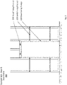
- doors 110 need to be mounted within walls 120 (the walls typically made of masonry or stud and plasterboard, but in the example shown the wall is made from metal stud and plasterboard).
- the structure 200 of a typical building provides a wooden frame into which the door 110 can be mounted and on to which the walls 120 can be fixed.
- Such an arrangement 200 would include door lining fixings 210 (on to which a door 110 can be mounted) and other structural fixings such as head fixing brackets 230 and jamb fixing brackets 220.
- FIG. 3 To fix a door 110 to a door lining 210, a known door hinge and mounting bracket arrangement 300 is shown in Figure 3 and will now be described in more detail below.
- a door 310 is mounted to hinge 320 using screws (not shown) provided through one plate of the hinge 320 into the door 310.
- the second plate of the hinge 320 is attached to a timber door lining 340 using a screw 335 which is fixed through the timber door lining 340, some non-combustible packers 370 a metal partition stud 370 and into a wood fixing portion 380.
- Further screws 335 may be provided to fix the timber door lining 340 through the non-combustible packers 370, the metal partition stud 370 to the wood fixing portion 380.
- a stop 330 is typically provided adjacent to the door 310 and also fixed to the timber door lining 340.
- architrave 350 (usually made from materials such as timber or MDF) is provided to cover the wall-facing sides of the timber door lining 340 and the edges of the plasterboard 360 that are adjacent to the timber door lining 340.
- Further metal partition studs 370 are provided along the wall.
- aspects and/or embodiments seek to provide an adjustable fixing bracket for fixing linings to walls or partitions and specifically a bracket that can remove the need for using non-combustible packers when fixing doors to door linings in construction.
- a mounting bracket for a wall comprising an end portion and a pair of side portions, wherein: the end portion comprises at least one substantially flat plate having a plurality of fixing points, each fixing point for receiving a fastening member; the side portions each comprising at least one substantially flat plate and at least one fixing point, each fixing point for receiving a fastening member, and the side portions formed substantially perpendicular to the end portion and each side portion being substantially parallel to the other side portion.
- the mounting bracket of this aspect and/or embodiments can be adjusted at any point during installation, as the fixings are only covered at plastering or tacking stages of construction.
- this bracket can require no further packing materials, thus needing no testing in line with mixing various fire products and the resultant suitability when acting together with such packing materials. Additionally, as no further packing can be required to secure the lining, it follows that no further fire products are required to protect the packing materials.
- the end portion is operable to be mounted to a door lining.
- the side portions are operable to be mounted to one or more metal stud partitions.
- the bracket can require no predetermined stud locations to be fixed in place and can work in substantially any manufacturer setup approved detailing.
- Specific configurations of holes for fastening members can be provided in different embodiments of the bracket, or self-drilling screws can be used at the fixing points and no holes need be provided in the end and/or side portions.
- the side portions are operable to allow fixing to the door lining and plasterboard to be mounted to the wall without some components of the wall or door lining preventing installation of other components of the wall or door lining.
- Plasterboard can be mounted to the wall and the side portions can be fixed to the door lining without clashes between components of the wall and/or door lining. Clashes occur when components installed by one type of trade prevent other components being installed by another type of trade, and it is therefore preferred to avoid clashes if possible.
- the side portions are formed with the end portion to provide a plurality of lips on the end portion.
- the side portions meet the end portion substantially away from the edge of the end portion to form the plurality of lips on the end portion.
- the end portion is formed having lips on one side of each join with each side portion, forming two lips.
- the plurality of lips comprises at least one of the plurality of fixing points for receiving a fastening member.
- each of the plurality of lips comprises at least one of the plurality of fixing points for receiving a fastening member.
- lips By providing lips, fixing can be more easily achieved when installing the bracket as the fixing points are accessible from the surface of the bracket that is exposed during installation.
- One of the lips can be used for fixing, or both lips can be used for fixing the bracket.
- the side portions each comprise a plurality of fixing points, each fixing point for receiving a fastening member.
- Metal stud partitions in construction require multiple fixing points within approved details as fixing into the jamb stud alone is not suitable within metal partition systems due to the resultant twist and movement in differing materials.
- multiple fixing points in the bracket multiple fixing points can be provided when installing the bracket.
- any or any combination of the fixing points comprise holes.
- the fixing points can be provided as holes into which screws and/or other fasteners can be received.
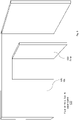
- Bracket 400 there is shown a bracket 400 according to an embodiment.
- the bracket 400 is a T-shaped framing member which allows the fixing of linings to walls or partitions with a substantially high degree of accuracy as typically needed in construction detailing, including fire details and minimal gap requirements in accordance with manufacturer guidelines.
- the bracket 400 is provided having an end portion 430 and two side portions 410, each side portion 410 in the T-shaped arrangement with the end portion 430.
- the configuration of the portions is such that the two side portions 410 extend perpendicular from the end portion and parallel to each other.
- the end portion 430 and the two side portions 410 are all flat plates, in this embodiment made from metal, formed by welding the plates together. In other embodiments, alternative materials can be used. In other embodiments, the part may be formed by casting or other process and formed as a single part.
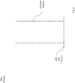
- the end face 510 (of the end portion 430) is provided with screw holes 520 at either side of the face 510, for mounting when installed.
- bracket side portion face 600 there is shown a bracket side portion face 600 according to an embodiment which will now be described in more detail.
- the side face 610 (of each of the side portions 410) has at least one screw hole 620 provided along its face, for mounting when installed.
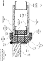
- FIG. 7 there is shown a cross-section view of a door hinge and mounting bracket arrangement 700 according to an embodiment which will now be described in more detail below.
- the wall construction uses stud partitions.
- a door 710 is mounted to a hinge 720.
- the hinge 720 is provided having two hinge plates able to move relative to each other around an axis defined where the two plates are joined.
- One hinge plate is mounted to the door 710 using screws (not shown).
- the other hinge plate is mounted to one side of the timber door lining 740.
- the bracket 730 is mounted to the other side of the timber door lining 740 using screws 760a.
- the bracket 730 is also mounted to two metal partition studs 770 at two positions along the wall using screws 760b, 760c on each side of the wall.
- the bracket 730 can be attached to the solid wall at various positions as appropriate instead of to the metal stud partitions and/or any wood fixing 790.
- the timber door lining can also have a stop 735 mounted on it adjacent to the door 710 and an architrave 750 to cover the side of the timber door lining 740 and the edge of the plasterboard 780.
- the fixing bracket 730 is fixed to the lining 740 prior to installation to the wall or partition by screws.
- the bracket 730 can be fixed at any suitable location along the long legs (i.e. side portions 410) of the bracket 730.
- the bracket 730 is fixed via the predrilled holes (i.e. screw holes 620) along the legs to the timber 790 within the jamb lining, the bracket can then be screwed through at any location to the next stud 770 for rigidity, using self-drilling screws into metal, or timber screws into timber.
- the bracket 730 of this embodiment thus requires no predetermined stud locations to be fixed in place and will work in substantially any manufacturer setup approved detailing.
- the fixing can be adjusted at any point during installation, as the fixings are only covered at the plastering or tacking stages of construction.
- the bracket 730 can also require no further packing materials, thus not need (fire safety) testing and/or certification of mixed fire products and the resultant suitability when acting together. As the bracket 730 does not need further packing to secure the lining, this can mean that no further fire products are required to protect packing material.
- the fixing bracket 730 can be manufactured at various typical wall or partition sizes and yet remain the same in fixing and design detailing, whether fixing the jamb or head of the lining to partitions or walls.
- Any feature in one aspect may be applied to other aspects, in any appropriate combination.
- method aspects may be applied to system aspects, and vice versa.
- any, some and/or all features in one aspect can be applied to any, some and/or all features in any other aspect, in any appropriate combination.
Landscapes
- Engineering & Computer Science (AREA)
- Mechanical Engineering (AREA)
- Civil Engineering (AREA)
- Structural Engineering (AREA)
- Special Wing (AREA)
Applications Claiming Priority (1)
| Application Number | Priority Date | Filing Date | Title |
|---|---|---|---|
| GB202106775 | 2021-05-12 |
Publications (1)
| Publication Number | Publication Date |
|---|---|
| EP4089260A1 true EP4089260A1 (fr) | 2022-11-16 |
Family
ID=81653704
Family Applications (1)
| Application Number | Title | Priority Date | Filing Date |
|---|---|---|---|
| EP22173130.0A Withdrawn EP4089260A1 (fr) | 2021-05-12 | 2022-05-12 | Support de fixation de porte |
Country Status (1)
| Country | Link |
|---|---|
| EP (1) | EP4089260A1 (fr) |
Citations (4)
| Publication number | Priority date | Publication date | Assignee | Title |
|---|---|---|---|---|
| DE2501043A1 (de) * | 1975-01-13 | 1976-07-15 | Adolf Holp | Vorrichtung zur nicht sichtbaren befestigung eines tuerfutters am mauerwerk |
| EP1396602A1 (fr) * | 2002-09-04 | 2004-03-10 | MDF Profiles Limited | Moyen de fixation et procédé |
| EP3130737B1 (fr) * | 2015-08-10 | 2019-03-20 | Jeld Wen Türen GmbH | Système de paroi doté d'une ouverture de porte |
| US10871025B2 (en) * | 2018-09-21 | 2020-12-22 | Express Products, Inc. | Two in one door hanger bracket |
-
2022
- 2022-05-12 EP EP22173130.0A patent/EP4089260A1/fr not_active Withdrawn
Patent Citations (4)
| Publication number | Priority date | Publication date | Assignee | Title |
|---|---|---|---|---|
| DE2501043A1 (de) * | 1975-01-13 | 1976-07-15 | Adolf Holp | Vorrichtung zur nicht sichtbaren befestigung eines tuerfutters am mauerwerk |
| EP1396602A1 (fr) * | 2002-09-04 | 2004-03-10 | MDF Profiles Limited | Moyen de fixation et procédé |
| EP3130737B1 (fr) * | 2015-08-10 | 2019-03-20 | Jeld Wen Türen GmbH | Système de paroi doté d'une ouverture de porte |
| US10871025B2 (en) * | 2018-09-21 | 2020-12-22 | Express Products, Inc. | Two in one door hanger bracket |
Similar Documents
| Publication | Publication Date | Title |
|---|---|---|
| US6176053B1 (en) | Wall track assembly and method for installing the same | |
| US5848512A (en) | Structural member for wall assembly | |
| US10184242B2 (en) | Hanger for fire separation wall | |
| US5279091A (en) | Building enclosure assemblies | |
| CA2970646C (fr) | Support robuste destine a un mur de separation incendie | |
| US8615942B2 (en) | Metal header frame for a building wall | |
| US11898348B2 (en) | Curtain wall L-bracket and clip assembly | |
| US12546106B2 (en) | Drywall hanger | |
| US11193271B2 (en) | Process for producing a recess in the base region of a wall construction, corresponding wall construction and system and construction element therefor | |
| US20220243455A1 (en) | Drywall Spacing Joist Hanger | |
| KR20200049806A (ko) | 표준 체결구를 수용하는 탄성 벽판 설치 채널 | |
| US10724233B2 (en) | Curtain wall saddle-bracket and clip assembly | |
| US8650818B1 (en) | Mounting apparatus for door jambs and window frames | |
| EP4089260A1 (fr) | Support de fixation de porte | |
| US20210108410A1 (en) | Fasteners and wall assemblies | |
| US20240376704A1 (en) | Drywall Spacing Joist Hanger | |
| EP0011358B1 (fr) | Procédé pour attacher des panneaux à des poutres en acier | |
| WO2010089590A1 (fr) | Ensemble cadre de porte et procédé d'installation de portes | |
| JP6633320B2 (ja) | 支持具および天井構造 | |
| JP7693376B2 (ja) | 枠部材の施工方法及び引き戸ユニット | |
| GB2637784A (en) | Frame for an access panel or door | |
| AU2015100667B4 (en) | Alu-Eave. Aluminium composite sheet eave lining system for standard residential eaves. | |
| JPS62206140A (ja) | 新規な中空間仕切壁及びその組立方法 | |
| KR20240125687A (ko) | 내부 코너부에서 월보드를 고정하기 위한 월보드 고정 장치 | |
| AU2012201796A1 (en) | Improved Corner Member |
Legal Events
| Date | Code | Title | Description |
|---|---|---|---|
| PUAI | Public reference made under article 153(3) epc to a published international application that has entered the european phase |
Free format text: ORIGINAL CODE: 0009012 |
|
| STAA | Information on the status of an ep patent application or granted ep patent |
Free format text: STATUS: REQUEST FOR EXAMINATION WAS MADE |
|
| 17P | Request for examination filed |
Effective date: 20220512 |
|
| AK | Designated contracting states |
Kind code of ref document: A1 Designated state(s): AL AT BE BG CH CY CZ DE DK EE ES FI FR GB GR HR HU IE IS IT LI LT LU LV MC MK MT NL NO PL PT RO RS SE SI SK SM TR |
|
| STAA | Information on the status of an ep patent application or granted ep patent |
Free format text: STATUS: THE APPLICATION IS DEEMED TO BE WITHDRAWN |
|
| 18D | Application deemed to be withdrawn |
Effective date: 20230517 |