EP4089302A1 - Verfahren zur unterstützung des gangeinlegens von stillstandsschaltgetrieben - Google Patents
Verfahren zur unterstützung des gangeinlegens von stillstandsschaltgetrieben Download PDFInfo
- Publication number
- EP4089302A1 EP4089302A1 EP22169637.0A EP22169637A EP4089302A1 EP 4089302 A1 EP4089302 A1 EP 4089302A1 EP 22169637 A EP22169637 A EP 22169637A EP 4089302 A1 EP4089302 A1 EP 4089302A1
- Authority
- EP
- European Patent Office
- Prior art keywords
- pressure
- hydraulic pump
- cylinder chamber
- actuating
- working line
- Prior art date
- Legal status (The legal status is an assumption and is not a legal conclusion. Google has not performed a legal analysis and makes no representation as to the accuracy of the status listed.)
- Granted
Links
Images

Classifications
-
- F—MECHANICAL ENGINEERING; LIGHTING; HEATING; WEAPONS; BLASTING
- F16—ENGINEERING ELEMENTS AND UNITS; GENERAL MEASURES FOR PRODUCING AND MAINTAINING EFFECTIVE FUNCTIONING OF MACHINES OR INSTALLATIONS; THERMAL INSULATION IN GENERAL
- F16H—GEARING
- F16H61/00—Control functions within control units of change-speed- or reversing-gearings for conveying rotary motion ; Control of exclusively fluid gearing, friction gearing, gearings with endless flexible members or other particular types of gearing
- F16H61/38—Control of exclusively fluid gearing
- F16H61/40—Control of exclusively fluid gearing hydrostatic
- F16H61/42—Control of exclusively fluid gearing hydrostatic involving adjustment of a pump or motor with adjustable output or capacity
- F16H61/431—Pump capacity control by electro-hydraulic control means, e.g. using solenoid valves
-
- F—MECHANICAL ENGINEERING; LIGHTING; HEATING; WEAPONS; BLASTING
- F04—POSITIVE - DISPLACEMENT MACHINES FOR LIQUIDS; PUMPS FOR LIQUIDS OR ELASTIC FLUIDS
- F04B—POSITIVE-DISPLACEMENT MACHINES FOR LIQUIDS; PUMPS
- F04B49/00—Control, e.g. of pump delivery, or pump pressure of, or safety measures for, machines, pumps, or pumping installations, not otherwise provided for, or of interest apart from, groups F04B1/00 - F04B47/00
- F04B49/002—Hydraulic systems to change the pump delivery
-
- F—MECHANICAL ENGINEERING; LIGHTING; HEATING; WEAPONS; BLASTING
- F16—ENGINEERING ELEMENTS AND UNITS; GENERAL MEASURES FOR PRODUCING AND MAINTAINING EFFECTIVE FUNCTIONING OF MACHINES OR INSTALLATIONS; THERMAL INSULATION IN GENERAL
- F16H—GEARING
- F16H61/00—Control functions within control units of change-speed- or reversing-gearings for conveying rotary motion ; Control of exclusively fluid gearing, friction gearing, gearings with endless flexible members or other particular types of gearing
- F16H61/38—Control of exclusively fluid gearing
- F16H61/40—Control of exclusively fluid gearing hydrostatic
- F16H61/4008—Control of circuit pressure
- F16H61/4017—Control of high pressure, e.g. avoiding excess pressure by a relief valve
-
- F—MECHANICAL ENGINEERING; LIGHTING; HEATING; WEAPONS; BLASTING
- F16—ENGINEERING ELEMENTS AND UNITS; GENERAL MEASURES FOR PRODUCING AND MAINTAINING EFFECTIVE FUNCTIONING OF MACHINES OR INSTALLATIONS; THERMAL INSULATION IN GENERAL
- F16H—GEARING
- F16H61/00—Control functions within control units of change-speed- or reversing-gearings for conveying rotary motion ; Control of exclusively fluid gearing, friction gearing, gearings with endless flexible members or other particular types of gearing
- F16H61/38—Control of exclusively fluid gearing
- F16H61/40—Control of exclusively fluid gearing hydrostatic
- F16H61/46—Automatic regulation in accordance with output requirements
- F16H61/47—Automatic regulation in accordance with output requirements for achieving a target output speed
-
- F—MECHANICAL ENGINEERING; LIGHTING; HEATING; WEAPONS; BLASTING
- F16—ENGINEERING ELEMENTS AND UNITS; GENERAL MEASURES FOR PRODUCING AND MAINTAINING EFFECTIVE FUNCTIONING OF MACHINES OR INSTALLATIONS; THERMAL INSULATION IN GENERAL
- F16H—GEARING
- F16H61/00—Control functions within control units of change-speed- or reversing-gearings for conveying rotary motion ; Control of exclusively fluid gearing, friction gearing, gearings with endless flexible members or other particular types of gearing
- F16H61/04—Smoothing ratio shift
- F16H2061/047—Smoothing ratio shift by preventing or solving a tooth butt situation upon engagement failure due to misalignment of teeth
-
- F—MECHANICAL ENGINEERING; LIGHTING; HEATING; WEAPONS; BLASTING
- F16—ENGINEERING ELEMENTS AND UNITS; GENERAL MEASURES FOR PRODUCING AND MAINTAINING EFFECTIVE FUNCTIONING OF MACHINES OR INSTALLATIONS; THERMAL INSULATION IN GENERAL
- F16H—GEARING
- F16H61/00—Control functions within control units of change-speed- or reversing-gearings for conveying rotary motion ; Control of exclusively fluid gearing, friction gearing, gearings with endless flexible members or other particular types of gearing
- F16H61/04—Smoothing ratio shift
- F16H2061/0474—Smoothing ratio shift by smoothing engagement or release of positive clutches; Methods or means for shock free engagement of dog clutches
-
- F—MECHANICAL ENGINEERING; LIGHTING; HEATING; WEAPONS; BLASTING
- F16—ENGINEERING ELEMENTS AND UNITS; GENERAL MEASURES FOR PRODUCING AND MAINTAINING EFFECTIVE FUNCTIONING OF MACHINES OR INSTALLATIONS; THERMAL INSULATION IN GENERAL
- F16H—GEARING
- F16H2200/00—Transmissions for multiple ratios
- F16H2200/003—Transmissions for multiple ratios characterised by the number of forward speeds
- F16H2200/0034—Transmissions for multiple ratios characterised by the number of forward speeds the gear ratios comprising two forward speeds
-
- F—MECHANICAL ENGINEERING; LIGHTING; HEATING; WEAPONS; BLASTING
- F16—ENGINEERING ELEMENTS AND UNITS; GENERAL MEASURES FOR PRODUCING AND MAINTAINING EFFECTIVE FUNCTIONING OF MACHINES OR INSTALLATIONS; THERMAL INSULATION IN GENERAL
- F16H—GEARING
- F16H3/00—Toothed gearings for conveying rotary motion with variable gear ratio or for reversing rotary motion
- F16H3/02—Toothed gearings for conveying rotary motion with variable gear ratio or for reversing rotary motion without gears having orbital motion
- F16H3/08—Toothed gearings for conveying rotary motion with variable gear ratio or for reversing rotary motion without gears having orbital motion exclusively or essentially with continuously meshing gears, that can be disengaged from their shafts
- F16H3/087—Toothed gearings for conveying rotary motion with variable gear ratio or for reversing rotary motion without gears having orbital motion exclusively or essentially with continuously meshing gears, that can be disengaged from their shafts characterised by the disposition of the gears
- F16H3/089—Toothed gearings for conveying rotary motion with variable gear ratio or for reversing rotary motion without gears having orbital motion exclusively or essentially with continuously meshing gears, that can be disengaged from their shafts characterised by the disposition of the gears all of the meshing gears being supported by a pair of parallel shafts, one being the input shaft and the other the output shaft, there being no countershaft involved
-
- F—MECHANICAL ENGINEERING; LIGHTING; HEATING; WEAPONS; BLASTING
- F16—ENGINEERING ELEMENTS AND UNITS; GENERAL MEASURES FOR PRODUCING AND MAINTAINING EFFECTIVE FUNCTIONING OF MACHINES OR INSTALLATIONS; THERMAL INSULATION IN GENERAL
- F16H—GEARING
- F16H47/00—Combinations of mechanical gearing with fluid clutches or fluid gearing
- F16H47/02—Combinations of mechanical gearing with fluid clutches or fluid gearing the fluid gearing being of the volumetric type
Definitions
- the invention relates to a method for supporting the gear engagement of a standstill gearbox of a travel drive, which comprises a hydraulic pump and a hydraulic motor.
- Hydrostatic travel drives for mobile work machines are known in which a hydraulic pump and one or more hydraulic motors are connected to one another in a closed hydraulic circuit.
- the hydraulic pump is driven by an internal combustion engine - e.g. a diesel engine - and the hydraulic motors finally drive the mobile working machine - e.g. via a respective wheel.
- the delivery volume of the hydraulic pump of such travel drives is adjustable. This can e.g. B. at a constant speed of the internal combustion engine, the volume flow conveyed by the hydraulic pump can be changed in a closed circuit and thus an output speed of the hydraulic motors or the wheels - i.e. a driving speed of the mobile machine - can be adjusted.
- the displacement of the hydraulic motor or motors can also be adjusted. This makes it possible, for example, when starting up the affected mobile machine, to first increase the delivery volume of the hydraulic pump from zero to the maximum value, and then to reduce the displacement of the hydraulic motors from the maximum for faster travel. With this reduction, the output speed is increased while the volume flow remains the same.
- Travel drives of construction machines are often equipped with standstill gears in addition to a hydrostatic transmission in order to enable a higher ratio spread.
- the gears are shifted when the vehicle is stationary by means of an electrohydraulic actuation.
- the shift request is made by the driver and is only permitted under certain conditions.
- engaging the gear can fail.
- An example of this is in DE 10 2009 053 031 A1 disclosed.
- the invention is based on the object of producing a method that will overcome the disadvantages listed above.
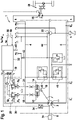
- a hydrostatic travel drive 1 has a hydraulic pump 2 which is fluidically connected in a closed hydraulic circuit via the working lines 4 and 6 to a hydraulic motor 78 to supply it with pressure medium.
- the hydraulic pump 2 is coupled to a drive machine 54 via a drive shaft 8 for the transmission of a torque.
- the coupling is not translated here, so that the speed of the drive engine and the hydraulic pump 2 are identical.
- the hydraulic pump 2 is designed as an axial piston pump with a swash plate design and can be operated in both directions of rotation and both in pump and motor mode. It has an adjustable displacement volume V P and an adjustment device 10 designed as a double-acting hydraulic cylinder.
- the hydraulic cylinder 10 has a first cylinder chamber 12 and a second cylinder chamber 14 counteracting the first.
- the latter is connected to a control pressure line 20 which can be supplied with control pressure medium via a control pressure connection p s and via a feed pump 22 which is seated on the same drive shaft 8 as the hydraulic pump 2 .
- the second cylinder chamber 14 is connected via a second actuating pressure line 24 to a second pressure reducing valve 26 which is connected to the control pressure line 20 .
- the pressure reducing valves 18, 26 can be actuated electromagnetically, the control pressure p a or p b resulting in the control pressure line 16 or 24 being proportional to a control current l a or l b of the electromagnet a or b according to a valve characteristic.
- the actuating pressures p a , p b of the cylinder chambers 12 , 14 can thus be controlled via the electromagnetic actuation of the pressure-reducing valves 18 , 26 by specifying the control currents la , lb .
- the electromagnets a, b of the pressure reducing valves 18, 26 are signal-connected to an electronic control unit 32 via a respective signal line 28 or 30, respectively.
- the hydrostatic travel drive 1 has a speed detection unit 34 via which a speed np of the hydraulic pump 2 can be detected and transmitted to the electronic control unit 32 via a signal line 36 .
- the travel drive 1 also has a speed detection unit (not shown) via which the speed n M of the hydraulic motor can be detected and transmitted to the electronic control unit 32 via the signal line 38 .
- the hydrostatic travel drive 1 has a pressure-limiting valve 40 in each case, which is connected to the respective working line 4, 6. Both pressure relief valves 40 have their outputs connected to a feed pressure line 44 which is connected to the feed pump 22 .
- the feed pressure line 44 is fluidically connected to the control pressure line 20 via a throttle 42 . If the pressure-limiting valves respond, pressure medium is released into the feed pressure line 44, as a result of which energy losses are lower than if the release to the tank T were to occur.
- the pressure-limiting valves 40 each have a feed or suction function in the form of a check valve.
- the hydrostatic travel drive 1 can be operated both in traction mode and in towing or braking mode.
- the hydraulic pump 2 works in pump mode, in braking mode it works in motor mode.
- the hydraulic pump 2 is designed such that the pressure p that is present in the high-pressure line of the working lines 4, 6 counteracts the actuating pressure p a or p b that is then effective and acts in the direction of its own reduction.
- the hydraulic pump 2 has a structurally implemented control loop.
- the hydraulic pump 2 designed as an axial piston pump with a swash plate design, this is implemented in such a way that a control disk of the hydraulic pump 2 is arranged twisted with respect to an axis of rotation of its cylinder drum.
- the travel drive has a standstill shift transmission 99, which has at least two gears in order to enable the ratio spread to be increased.
- the gears are shifted when the vehicle is stationary by means of an electrohydraulic actuation (not shown).
- the gear signal is shown in the upper section of figure 2 .
- G1 means that the first gear of the standstill gearbox 99 is engaged and
- G2 means that the second gear of the standstill gearbox 99 is engaged.
- the release function for gear engagement is shown in the second section of figure 2 . If the value is equal to 0 means that the gear engagement cannot be performed. Conversely, if the value is equal to 1, it means that the gear can be engaged.
- the control currents I a and I b are shown, which are regulated during gear engagement in order to carry out the gear engagement.
- the pressure generated by the hydraulic pump 2 in one of the working lines 4, 6 is shown in the lower section.
- the control unit 32 is configured to detect a gear change command and to start the gear change process.
- control unit 32 When the control unit detects the gear change command, the control unit 32 will start to regulate the swivel angle of the hydraulic pump 2 in order to carry out the gear engagement.
- control current I a is first increased in order to increase the actuating pressure p a in the first cylinder chamber and to cause the swivel angle of the hydraulic pump 2 to rise positively.
- the pressure generated by the hydraulic pump 2 is allowed to rise up to a predetermined value P L .
- P L a predetermined value
- the control unit 32 detects that the gear engagement has not yet been carried out at the predetermined value P L (as at the point M in figure 2 was shown), the drive current la is brought back to 0 and the control unit 32 will start to regulate the swivel angle of the hydraulic pump 2 in such a way that a negative slope of the swivel angle of the hydraulic pump 2 is caused.
- this goal is achieved with an increase in the control current l b in order to increase the actuating pressure p b in the second cylinder chamber and accordingly to cause a negative increase in the swivel angle of the hydraulic pump 2, which causes an increase in the pressure in the working line 6.
- the value of P L is the same for positive and for negative swivel angles of the hydraulic pump. However, according to a further exemplary embodiment, this value can also be different. The value is selected in such a way that the hydraulic motor 78 of the travel drive 1, which is supplied with this pressure P L , does not cause any movement of a vehicle on which the travel drive 1 is installed.
- the predefined trajectory for the actuating pressures pa, pb is preferably selected in such a way that the control pressure at the start of the trajectory does not cause any change in the swivel angle of the hydraulic pump 2 .
Landscapes
- Engineering & Computer Science (AREA)
- General Engineering & Computer Science (AREA)
- Mechanical Engineering (AREA)
- Control Of Fluid Gearings (AREA)
Abstract
wobei das Verfahren folgende Schritte umfasst:
a. Erfassung eines Gangwechselbefehls;
b. Beeinflussung des Stelldrucks (pa, pb) in dem wenigstens einen ersten Zylinderraum (12, 14) sodass der Druck (p) der Hydropumpe (2) in einer zwischen der ersten und der zweiten Arbeitsleitung (4, 6) erhöht wird;
wobei die Beeinflussung des Stelldrucks (pa, pb) gestoppt wird, wenn der Druck (p) der Hydropumpe (2) in der einen Arbeitsleitung (4, 6) einen ersten vorgegebenen Wert erreicht hat.
Description
- Die Erfindung betrifft ein Verfahren zur Unterstützung des Gangeinlegens von einem Stillstandsschaltgetriebe eines Fahrantriebes, der eine Hydropumpe und einen Hydromotor umfasst.
- Es sind hydrostatische Fahrantriebe für mobile Arbeitsmaschinen bekannt, bei denen eine Hydropumpe und ein oder mehrere Hydromotoren in einem geschlossenen hydraulischen Kreis miteinander verbunden sind. Die Hydropumpe wird von einem Verbrennungsmotor - z.B. einem Dieselmotor - angetrieben, und die Hydromotoren treiben schließlich die mobile Arbeitsmaschine - z.B. über ein jeweiliges Rad - an.
- Die Hydropumpe derartiger Fahrantriebe ist in ihrem Fördervolumen verstellbar. Damit kann z. B. bei konstanter Drehzahl des Verbrennungsmotors der von der Hydropumpe geförderte Volumenstrom im geschlossenen Kreis verändert werden und damit eine Abtriebsdrehzahl der Hydromotoren bzw. der Räder - also eine Fahrgeschwindigkeit der mobilen Arbeitsmaschine - verstellt werden.
- Weiterhin ist es bekannt, dass auch der oder die Hydromotoren in ihrem Schluckvolumen verstellbar sind. Damit ist es z.B. möglich beim Anfahren der betroffenen mobilen Arbeitsmaschine zunächst das Fördervolumen der Hydropumpe von Null ausgehend bis zum Maximalwert zu erhöhen, um dann für schnellere Fahrt das Schluckvolumen der Hydromotoren vom Maximum ausgehend zu reduzieren. Mit dieser Reduktion wird die Abtriebsdrehzahl bei gleichbleibendem Volumenstrom erhöht.
- Fahrantriebe von Baumaschinen sind häufig neben einem hydrostatischen Getriebe mit Stillstandsgetrieben ausgerüstet um eine höhere Übersetzungsspreizung zu ermöglichen. Das Schalten des Ganges erfolgt dabei im Stillstand mittels einer elektrohydraulischen Aktuierung. Die Schaltanforderung erfolgt durch den Fahrer und wird nur unter bestimmten Bedingungen zugelassen. Je nach Position der Getriebepaarungen kann das Einlegen des Ganges allerdings scheitern. Ein Beispiel davon ist in
DE 10 2009 053 031 A1 offenbart. - Um dieses Problem zu umgehen sind Lösungen bekannt, die automatisiert mittels der Hydrostatenansteuerung eine leichte Drehbewegung am Getriebeeingang erzeugen und damit die Blockierende Position im Getriebe lösen.
- Bei dieser bekannten Form der Unterstützung kann allerdings nicht sichergestellt werden, dass ein bestimmtes Moment beim Gangeinlegen nicht überschritten wird. Dies ist allerdings die typische Anforderung von Getriebeherstellern.
- Dem gegenüber liegt der Erfindung die Aufgabe zu Grunde, ein Verfahren herzustellen, dass die oben gelisteten Nachteile überwinden wird.
- Die vorliegende Erfindung wird unter Bezugnahme auf die beigefügten Figuren beschrieben, wobei sich gleiche Bezugszeichen auf gleiche Teile und / oder auf ähnliche Teile und / oder auf entsprechende Teile des Systems beziehen. Zu den Figuren:
-
Figur 1 zeigt schematisch einen Schaltplan eines Fahrantriebs gemäß dem Stand der Technik; -
Figur 2 zeigt schematisch ein Beispiel eines Zeitverlaufes von verscheidenden Größen während dem Umschalten gemäß einer Ausführungsform der vorliegenden Erfindung. - Im Folgenden wird die vorliegende Erfindung unter Bezugnahme auf bestimmte Ausführungsformen beschrieben, wie sie in den beigefügten Figuren gezeigt sind. Nichtsdestotrotz ist die vorliegende Erfindung nicht auf die besonderen Ausführungsformen beschränkt, die in der folgenden detaillierten Beschreibung beschrieben und in den Figuren gezeigt sind, sondern die beschriebenen Ausführungsformen veranschaulichen lediglich einige Aspekte der vorliegenden Erfindung, deren Schutzbereich durch die Ansprüche definiert ist.
- Weitere Änderungen und Variationen der vorliegenden Erfindung sind für den Fachmann klar. Die vorliegende Beschreibung umfasst somit alle Änderungen und / oder Variationen der vorliegenden Erfindung, deren Schutzbereich durch die Ansprüche definiert ist.
- Gemäß
Figur 1 hat ein hydrostatischer Fahrantrieb 1 eine Hydropumpe 2, die in geschlossenem hydraulischem Kreislauf über die Arbeitsleitungen 4 und 6 mit einem Hydromotor 78 zu dessen Druckmittelversorgung fluidisch verbunden ist. Dabei ist die Hydropumpe 2 mit einer Antriebsmaschine 54 über eine Triebwelle 8 zur Übertragung eines Drehmoments gekoppelt. Die Kopplung ist dabei nicht übersetzt, so dass die Drehzahl der Antriebsmaschine und der Hydropumpe 2 identisch sind. - Die Hydropumpe 2 ist als Axialkolbenpumpe in Schrägscheibenbauweise ausgestaltet und kann in beiden Drehrichtungen und sowohl im Pumpen- als auch im Motorbetrieb betrieben werden. Sie hat ein verstellbares Verdrängungsvolumen VP und eine als doppelt wirkender Hydrozylinder ausgestaltete Verstelleinrichtung 10.
- Der Hydrozylinder 10 hat eine erste Zylinderkammer 12 und eine der ersten entgegenwirkende, zweite Zylinderkammer 14. Die erste Zylinderkammer 12 ist über eine erste Stelldruckleitung 16 mit dem Ausgang eines ersten Druckreduzierventils 18 verbunden. Letztgenanntes ist an eine Steuerdruckleitung 20 angeschlossen, die über einen Steuerdruckanschluss ps und über eine Speisepumpe 22, die auf der gleichen Triebwelle 8, wie die Hydropumpe 2 sitzt, mit Steuerdruckmittel versorgbar ist.
- In gleicher Weise ist die zweite Zylinderkammer 14 über eine zweite Stelldruckleitung 24 mit einem zweiten Druckreduzierventil 26 verbunden, welches an die Steuerdruckleitung 20 angeschlossen ist.
- Die Druckreduzierventile 18, 26 sind elektromagnetisch betätigbar, wobei der jeweils in der Stelldruckleitung 16 bzw. 24 resultierende Stelldruck pa bzw. pb gemäß einer Ventilkennlinie proportional zu einem Ansteuerstrom la bzw. lb des Elektromagnets a bzw. b ist. Über die elektromagnetische Betätigung der Druckreduzierventile 18, 26 können somit über die Vorgabe der Ansteuerströme la, lb die Stelldrücke pa, pb der Zylinderkammern 12, 14 gesteuert werden. Zu diesem Zweck sind die Elektromagnete a, b der Druckreduzierventile 18, 26 über eine jeweilige Signalleitung 28 bzw. 30 mit einer elektronischen Steuereinheit 32 signalverbunden.
- Des Weiteren hat der hydrostatische Fahrantrieb 1 eine Drehzahlerfassungseinheit 34, über die eine Drehzahl np der Hydropumpe 2 erfassbar und über eine Signalleitung 36 an die elektronische Steuereinheit 32 übermittelbar ist. Ebenso hat der Fahrantrieb 1 eine Drehzahlerfassungseinheit (nicht dargestellt), über die die Drehzahl nM des Hydromotors erfassbar und über die Signalleitung 38 an die elektronische Steuereinheit 32 übermittelbar ist.
- Zur sicherheitsrelevanten Druckabsicherung der Arbeitsleitungen 4, 6 gegen Überlast hat der hydrostatische Fahrantrieb 1 jeweils ein Druckbegrenzungsventil 40, das mit der jeweiligen Arbeitsleitung 4, 6 verbunden ist. Beide Druckbegrenzungsventile 40 sind mit ihren Ausgängen an eine Speisedruckleitung 44 angeschlossen, die mit der Speisepumpe 22 verbunden ist. Die Speisedruckleitung 44 ist über eine Drossel 42 mit der Steuerdruckleitung 20 fluidisch verbunden. Im Falle des Ansprechens der Druckbegrenzungsventile wird somit Druckmittel in die Speisedruckleitung 44 entspannt, wodurch energetischen Verluste geringer sind, als wenn die Entspannung zum Tank T hin geschähe. Die Druckbegrenzungsventile 40 weisen jeweils eine Speise- oder Nachsaugfunktion in Form eines Rückschlagventils auf.
- Der hydrostatische Fahrantrieb 1 kann sowohl im Zugbetrieb als auch im Schlepp- oder Bremsbetrieb betrieben werden. Im Zugbetrieb arbeitet die Hydropumpe 2 im Pumpenbetrieb, im Bremsbetrieb arbeitet sie im Motorbetrieb. Zudem ist die Hydropumpe 2 reversierbar, das heißt ihr Verdrängungsvolumen VP ist über die Verstelleinrichtung 10 beidseitig einer Neutralstellung mit Nullvolumen VP = 0 verstellbar. Dadurch ist bei gleichbleibender Drehrichtung der Triebwelle 8 und der Antriebsmaschine (Dieselmotor) eine Fahrtrichtungsumkehr möglich.
- Die elektronische Steuereinheit 32 ist über eine Signalleitung 46 mit einer Bedienerschnittstelle in Form eines Fahrpedals (nicht dargestellt) verbunden. Über das Fahrpedal wird dabei von einem Fahrer oder einer Fahrerin eine Geschwindigkeitsanforderung an die elektronische Steuereinheit 32 übermittelt. Diese kann sowohl die Rückwärtsfahrt als auch die Vorwärtsfahrt betreffen. Wird das Fahrpedal betätigt, so entspricht das dem Zug- oder Pumpenbetrieb der Hydropumpe 2, wird das Fahrpedal hingegen zurückgenommen, entspricht dies dem Brems- oder Motorbetrieb der Hydropumpe 2. Auch die Betätigung einer Fahrbremse (nicht dargestellt) entspricht dem Brems- oder Motorbetrieb der Hydropumpe 2. Die Steuereinheit ist derart ausgestaltet, dass sie anhand der genannten Betätigung den entsprechenden Betrieb ermitteln kann. Zur Auswahl einer Fahrtrichtung weist der hydrostatische Fahrantrieb 1 zudem einen betätigbaren Fahrtrichtungsschalter (nicht dargestellt) auf, der über eine Signalleitung 48 mit der elektronischen Steuereinheit 32 signalverbunden ist. In Abhängigkeit seiner Stellung erfolgt die Ansteuerung der Hydropumpe 2 in ihrem reversierten oder nicht reversierten Verstellbereich, also diesseits oder jenseits der Neutralstellung des Hubvolumens der Hydropumpe 2. Für die weitere Betrachtung seien folgende Fahrzustände definiert:
- Vorwärtsfahrt, Zugbetrieb: Druckbeaufschlagung der ersten Zylinderkammer 12 über die erste Stelldruckleitung 16 und das erste Druckreduzierventil 18 mit dem erstem Stellruck pa durch Ansteuern des ersten Druckreduzierventils 18 mit dem Ansteuerstrom la über die Steuereinheit 32 über die erste Signalleitung 28.
- Vorwärtsfahrt, Bremsbetrieb: Druckbeaufschlagung der zweiten Zylinderkammer 14 über die zweite Stelldruckleitung 24 und das zweite Druckreduzierventil 26 mit dem zweiten Stelldruck pb durch Ansteuern des zweiten Druckreduzierventils 26 mit dem Ansteuerstrom lb über die Steuereinheit 32 über die Signalleitung 30.
- Rückwärtsfahrt, Zugbetrieb: Druckbeaufschlagung der zweiten Zylinderkammer 14 über die Kette 24, 26, 30, 32.
- Rückwärtsfahrt, Bremsbetrieb: Druckbeaufschlagung der ersten Zylinderkammer 12 über die Kette 16, 18, 28, 32.
- In dem Ausführungsbeispiel ist die Hydropumpe 2 derart ausgestaltet, dass der Druck p, der in der hochdruckführenden der Arbeitsleitungen 4, 6 ansteht, dem dann wirksamen Stelldruck pa oder pb entgegenwirkt und in Richtung seiner eigenen Verringerung wirksam ist. Hierzu weist die Hydropumpe 2 eine konstruktiv realisierte Regelschleife auf. Im vorliegenden Fall der als Axialkolbenpumpe in Schrägscheibenbauweise ausgestalteten Hydropumpe 2 ist dies so realisiert, dass eine Steuerscheibe der Hydropumpe 2 bezüglich einer Drehachse ihrer Zylindertrommel verdrillt angeordnet ist.
- Mündungen derjenigen Zylinder, die mit der den Druck (Hochdruck) aufweisenden Druckniere Steuerscheibe verbunden sind, sind dadurch bezüglich einer Schwenkachse der Schrägscheibe unsymmetrisch verteilt angeordnet. Ebenso unsymmetrisch verteilt sind dann die an der Schrägscheibe abgestützten Endabschnitte der in den Zylindern geführten Arbeitskolben. Aus den somit unsymmetrisch wirkenden Stützkräften der Arbeitskolben resultiert an der Schrägscheibe ein im Pumpenbetrieb rückschwenkendes und im Motorbetrieb ausschwenkendes Moment. In der Konsequenz entsteht ein Zusammenhang in Form einer Pumpenkennlinie oder eines Kennfeldes von Pumpenkennlinien der Hydropumpe 2, in dem der jeweilige Stelldruck pa, pb in Abhängigkeit des Drucks p und des Hubvolumens VP der Hydropumpe 2, sowie von deren Drehzahl np beschreibbar ist. Diese Kennlinien oder Kennfelder sind vermessen und in der elektronischen Steuereinheit 32 zur Verarbeitung, insbesondere zur Ausführung des später beschriebenen Verfahrens, abgelegt.
- Weiterhin weist der Fahrantrieb ein Stillstandsschaltgetriebe 99 auf, das mindestens zwei Gänge umfasst, um die um höhere Übersetzungsspreizung zu ermöglichen. Das Schalten des Ganges erfolgt dabei im Stillstand mittels einer elektrohydraulischen Aktuierung (nicht dargestellt).
- In den nächsten Abschnitten mit Hilfe von
Figur 2 wird ein Verfahren zur Unterstützung des Gangeinlegens von dem Stillstandsschaltgetriebe 99 des Fahrantriebes 1 gemäß einer Ausführungsform der vorliegenden Erfindung beschrieben. - In dem oberen Abschnitt von
Figur 2 ist der Gangsignal dargestellt. Mit G1 bedeutet, dass der erste Gang des Stillstandsschaltgetriebes 99 eingelegt ist und mit G2 bedeutet, dass der zweite Gang des Stillstandsschaltgetriebes 99eingelegt ist. In dem zweiten Abschnitt vonFigur 2 ist die Freigabefunktion für das Gangeinlegen dargestellt. Wenn der Wert gleich 0 ist bedeutet, dass das Gangeinlegen nicht durchgeführt werden kann. Andersrum wenn der Wert gleich 1 ist bedeutet, dass das Gangeinlegen durchgeführt werden kann. In dem dritten Abschnitt sind die Ansteuerströme la und lb dargestellt, die während dem Gangeinlegen geregelt werden um das Gangeinlegen auszuführen. In dem unteren Abschnitt wird der durch die Hydropumpe 2 in einem der Arbeitsleitungen 4, 6 erzeugte Druck dargestellt. - Die Steuereinheit 32 ist konfiguriert einen Gangwechselbefehl zu erfassen und das Verfahren für den Gangwechsel zu starten.
- Wenn die Steuereinheit den Gangwechselbefehl erfasst, wird die Steuereinheit 32 anfangen, den Schwenkwinkel der Hydropumpe 2 zu regeln, um das Gangeinlegen zu durchführen. In dem gezeigten Beispiel wird zuerst der Ansteuerstrom la erhöht, um den Stelldruck pa in der ersten Zylinderkammer zu erhöhen und eine positive Steigung des Schwenkwinkels der Hydropumpe 2 zu verursachen.
- Durch die Erhöhung des Schwenkwinkels wird sich der durch die Hydropumpe 2 erzeugte Druck erhöhen und der Moment an dem Hydromotor 78 wird damit steigen, damit die blockierende Position im Getriebe gelöst werden kann.
- Der durch die Hydropumpe 2 erzeugte Druck wird bis zu einem vorgegebenen Wert PL steigen dürfen. Es kann aber natürlich sein, dass die Position im Getriebe schon bei einem Druck niedriger als PL gelöst wird, sodass das Gangeinlegen ausgeführt werden kann.
- Wenn aber die Steuereinheit 32 erfasst, dass bei dem vorgegebenen Wert PL das Gangeinlegen noch nicht ausgeführt wurde (wie bei dem Punkt M in
Figur 2 gezeigt wurde), wird der Ansteuerstrom la wieder auf 0 gebracht und die Steuereinheit 32 wird anfangen, den Schwenkwinkel der Hydropumpe 2 so zu regeln, dass eine negative Steigung des Schwenkwinkels der Hydropumpe 2 verursacht wird. In diesem Ausführungsbeispiel wird dieses Ziel mit einer Erhöhung des Ansteuerstromes lb erreicht, um den Stelldruck pb in der zweiten Zylinderkammer zu erhöhen und entsprechend eine negative Steigung des Schwenkwinkels der Hydropumpe 2 zu verursachen, was eine Steigung des Drucks in der Arbeitsleitung 6 verursacht. - Wie in dem unteren Abschnitt von
Figur 2 zu sehen ist, wird in diesem Fall die blockierende Position im Getriebe bei einem Druck kleiner als PL ausgelöst. - In diesem Ausführungsbeispiel ist der Wert von PL gleich für positive und für negative Schwenkwinkel der Hydropumpe. Allerdings gemäß einem weiteren Ausführungsbeispiel kann dieser Wert auch unterschiedlich sein. Der Wert ist so ausgewählt, dass der Hydromotor 78 des Fahrantriebes 1, der mit diesem Druck PL versorgt wird, keine Bewegung eines Fahrzeuges, auf dem der Fahrantrieb 1 installiert ist, verursacht.
- Wenn die Steuereinheit 32 erfasst, dass das Gangeinlegen ausgeführt wurde, wird die Freigabefunktion wieder auf 0 gebracht.
- Wie in
Figur 2 indirekt dargestellt wurde, ist die Beeinflussung des Stelldrucks pa, pb für die Regelung des von der Hydropumpe 2 erzeugten Druckes p in der ersten oder in der zweiten Zylinderammer 12, 14 mittels einer vorgegebenen Trajektorie ausgeführt. In der Tat zeigtFigur 2 , dass die Ansteuerströme eine vorgegebene Trajektorie folgen, die deswegen eine vorgegebene Trajektorie für den von der Hydropumpe 2 erzeugten Druck p verursacht. - Die vorgegebene Trajektorie für die Stelldrücke pa, pb wird vorzugsweise so ausgewählt, dass der Steuerdruck am Anfang der Trajektorie keine Schwenkwinkeländerung des Schwenkwinkels der Hydropumpe 2 versursacht.
- Während die vorliegende Erfindung unter Bezugnahme auf die oben beschriebenen Ausführungsformen beschrieben wurde, ist es für den Fachmann klar, dass es möglich ist, verschiedene Modifikationen, Variationen und Verbesserungen der vorliegenden Erfindung im Lichte der oben beschriebenen Lehre und innerhalb des Bereichs der beigefügten Ansprüche zu realisieren, ohne von dem Schutzbereich der Erfindung abzuweichen.
- Insbesondere, auch wenn in dem gezeigten Beispiel eine Erhöhung des Ansteuerstromes eine Erhöhung des Stelldrucks verursacht, kann es auch umgekehrt sein.
- Darüber hinaus wurden die Bereiche, auf denen Fachleute kundig sein dürften, hier nicht beschrieben, um die beschriebene Erfindung nicht unnötig zu verschleiern.
- Dementsprechend soll die Erfindung nicht durch die spezifischen veranschaulichenden Ausführungsformen beschränkt sein, sondern nur durch den Schutzbereich der beigefügten Ansprüche.
Claims (7)
- Verfahren zur Unterstützung des Gangeinlegens von einem Stillstandsschaltgetriebe (99) eines Fahrantriebes (1), wobei der Fahrantrieb mit der Hydropumpe (2), die mit einer Antriebsmaschine (54) gekoppelt ist, zur Druckmittelversorgung eines mit einem Abtrieb (80) gekoppelten Hydromotors (78) des Fahrantriebes (1) versehen ist, wobei die Hydropumpe (2) mittels einer ersten und einer zweiten Arbeitsleitung (4, 6) mit dem Hydromotor (78) verbunden ist, wobei die Hydropumpe (2) einen Stellzylinder (10) mit wenigstens einem ersten Zylinderraum (12, 14) und ein darüber verstellbares Hubvolumen (VP) hat und wenigstens ein elektrisch ansteuerbares Druckventil (18, 26) vorgesehen ist, über das der Zylinderraum (12, 14) mit einem verstellend wirksamen Stelldruck (pa, pb) beaufschlagbar ist, und mit einer Einrichtung (32), über die ein Druck (p) der Hydropumpe (2) in der ersten oder in der zweiten Arbeitsleitung (4, 6) mittels Beeinflussung des Stelldrucks (pa, pb) regelbar ist, wobei das Stillstandsschaltgetriebe (99) einen ersten und einen zweiten Gang umfasst,
das Verfahren dadurch gekennzeichnet, dass es folgende Schritte umfasst:a. Erfassung eines Gangwechselbefehls;b. Beeinflussung des Stelldrucks (pa, pb) in dem wenigstens einen ersten Zylinderraum (12, 14) sodass der Druck (p) der Hydropumpe (2) in einer zwischen der ersten und der zweiten Arbeitsleitung (4, 6) erhöht wird;wobei die Beeinflussung des Stelldrucks (pa, pb) gestoppt wird, wenn der Druck (p) der Hydropumpe (2) in der einen Arbeitsleitung (4, 6) einen ersten vorgegebenen Wert erreicht hat. - Verfahren nach Anspruch 1, wobei der Stellzylinder (10) weiterhin mit einem zweiten dem ersten Zylinderraum entgegenwirkenden Zylinderraum (12, 14) vorgesehen ist, wobei wenn der Druck (p) der Hydropumpe (2) in der einen Arbeitsleitung (4, 6) den ersten vorgegebenen Wert erreicht hat und das Umschalten zwischen dem ersten und dem zweiten Gang noch nicht ausgeführt wurde, der Stelldruck (pa, pb) in dem zweiten Zylinderraum (12,14) beeinflusst wird sodass der Druck (p) der Hydropumpe (2) in der anderen Arbeitsleitung (4, 6) erhöt wird, wobei die Beeinflussung des Stelldrucks (pa, pb) gestoppt wird, wenn der Druck (p) der Hydropumpe (2) in der anderen Arbeitsleitung (4, 6) einen zweiten vorgegebenen Wert erreicht hat.
- Verfahren nach Anspruch 1 oder 2, wobei nachdem der erste vorgegebene Wert und vorzugsweise der zweite vorgegebene Wert erreicht wird, der Druck (p) der Hydropumpe (2) mittels Beeinflussung des Stelldrucks (pa, pb) gesenkt wird.
- Verfahren nach einem der Ansprüche 1 bis 3, wobei der erste vorgegebene Wert und vorzugsweise der zweite vorgegebene Wert so ausgewählt werden, dass der Hydromotor (78) des Fahrantriebes (1) keine Bewegung eines Fahrzeuges, auf dem der Fahrantrieb (1) installiert ist, verursacht.
- Verfahren nach einem der Ansprüche 1 bis 4, wobei die genannte Beeinflussung des Stelldrucks (pa, pb) in dem einen Zylinderraum (12, 14) oder in dem anderen Zylinderraum (12, 14) mittels einer vorgegebenen Trajektorie für den von der Hydropumpe (2) erzeugten Druck (p) erfolgt.
- Verfahren nach Anspruch 5, wobei die vorgegebene Trajektorie für den von der Hydropumpe (2) erzeugten Druck (p) mittels einer vorgegebenen Trajektorie des Stelldrucks (pa, pb) erfolgt.
- Verfahren nach Anspruch 6, wobei die vorgegebene Trajektorie für den Stelldruck (pa, pb) so ausgewählt wird, dass der Steuerdruck am Anfang der Trajektorie keine Schwenkwinkeländerung des Schwenkwinkels der Hydropumpe (2) versursacht.
Applications Claiming Priority (1)
| Application Number | Priority Date | Filing Date | Title |
|---|---|---|---|
| DE102021204772.6A DE102021204772A1 (de) | 2021-05-11 | 2021-05-11 | Verfahren zur Unterstützung des Gangeinlegens von Stillstandsschaltgetrieben |
Publications (2)
| Publication Number | Publication Date |
|---|---|
| EP4089302A1 true EP4089302A1 (de) | 2022-11-16 |
| EP4089302B1 EP4089302B1 (de) | 2024-01-31 |
Family
ID=81386534
Family Applications (1)
| Application Number | Title | Priority Date | Filing Date |
|---|---|---|---|
| EP22169637.0A Active EP4089302B1 (de) | 2021-05-11 | 2022-04-25 | Verfahren zur unterstützung des gangeinlegens von stillstandsschaltgetrieben |
Country Status (2)
| Country | Link |
|---|---|
| EP (1) | EP4089302B1 (de) |
| DE (1) | DE102021204772A1 (de) |
Families Citing this family (1)
| Publication number | Priority date | Publication date | Assignee | Title |
|---|---|---|---|---|
| DE102024208779A1 (de) * | 2024-09-16 | 2026-03-19 | Robert Bosch Gesellschaft mit beschränkter Haftung | Verfahren zur Unterstützung des Gangeinlegens von Stillstandschaltgetrieben |
Citations (5)
| Publication number | Priority date | Publication date | Assignee | Title |
|---|---|---|---|---|
| DE102009053031A1 (de) | 2009-11-12 | 2011-05-19 | Linde Material Handling Gmbh | Hydrostatisches Getriebe |
| DE102011055178A1 (de) * | 2011-11-09 | 2013-05-16 | Linde Material Handling Gmbh | Hydrostatischer Fahrantrieb einer allradgetriebene Arbeitsmaschine |
| US20140041471A1 (en) * | 2012-08-13 | 2014-02-13 | Clark Equipment Company | Automatic shift of mechanical gearbox |
| DE102015215013A1 (de) * | 2015-08-06 | 2017-02-09 | Robert Bosch Gmbh | Getriebeanordnung, Fahrantrieb mit der Getriebeanordnung, sowie Verfahren zur Steuerung der Getriebeanordnung |
| DE102018210720A1 (de) * | 2018-06-29 | 2020-01-02 | Robert Bosch Gmbh | Hydrostatischer Fahrantrieb mit Druckabschneidung und Verfahren zum Kalibrieren der Druckabschneidung |
Family Cites Families (1)
| Publication number | Priority date | Publication date | Assignee | Title |
|---|---|---|---|---|
| DE19901443B4 (de) | 1999-01-15 | 2005-09-22 | Sauer-Sundstrand Gmbh & Co. | Antriebsstrang für ein Fahrzeug und Verfahren zum Steuern eines Antriebsstranges |
-
2021
- 2021-05-11 DE DE102021204772.6A patent/DE102021204772A1/de active Pending
-
2022
- 2022-04-25 EP EP22169637.0A patent/EP4089302B1/de active Active
Patent Citations (5)
| Publication number | Priority date | Publication date | Assignee | Title |
|---|---|---|---|---|
| DE102009053031A1 (de) | 2009-11-12 | 2011-05-19 | Linde Material Handling Gmbh | Hydrostatisches Getriebe |
| DE102011055178A1 (de) * | 2011-11-09 | 2013-05-16 | Linde Material Handling Gmbh | Hydrostatischer Fahrantrieb einer allradgetriebene Arbeitsmaschine |
| US20140041471A1 (en) * | 2012-08-13 | 2014-02-13 | Clark Equipment Company | Automatic shift of mechanical gearbox |
| DE102015215013A1 (de) * | 2015-08-06 | 2017-02-09 | Robert Bosch Gmbh | Getriebeanordnung, Fahrantrieb mit der Getriebeanordnung, sowie Verfahren zur Steuerung der Getriebeanordnung |
| DE102018210720A1 (de) * | 2018-06-29 | 2020-01-02 | Robert Bosch Gmbh | Hydrostatischer Fahrantrieb mit Druckabschneidung und Verfahren zum Kalibrieren der Druckabschneidung |
Also Published As
| Publication number | Publication date |
|---|---|
| EP4089302B1 (de) | 2024-01-31 |
| DE102021204772A1 (de) | 2022-11-17 |
Similar Documents
| Publication | Publication Date | Title |
|---|---|---|
| DE69529082T2 (de) | Drehzahländerer einer hydraulischen antriebsvorrichtung und steuerungsverfahren dafür | |
| EP0339202B1 (de) | Antriebseinrichtung für Maschinen und Fahrzeuge | |
| DE112010003533B4 (de) | Arbeitsfahrzeug | |
| DE68903731T2 (de) | Hydrostatisches getriebe und steuerung mit leistungsbegrenzung. | |
| EP3587794B1 (de) | Hydrostatischer fahrantrieb und verfahren zur steuerung des hydrostatischen fahrantriebes | |
| DE3145218A1 (de) | Antriebssystem und steuerung fuer verstellmotor(en) | |
| DE3147362A1 (de) | Hydrostatischer antrieb | |
| EP0615588B1 (de) | Hydrostatisches getriebe | |
| DE102017202273B4 (de) | Hydrostatisches Getriebe und Verfahren zur Bremsung damit | |
| DE68929357T2 (de) | Mechanisch-hydraulisches Getriebesystem und Steuerverfahren für Leistungsgetriebe mit einem solchen System | |
| EP1828643B1 (de) | Verfahren zum abbremsen eines mittels eines hydrostatischen getriebes angetriebenen fahrzeugs sowie ein hydrostatischer antrieb | |
| EP4089302B1 (de) | Verfahren zur unterstützung des gangeinlegens von stillstandsschaltgetrieben | |
| EP1561054B1 (de) | Steuerung für einen hydrostatischen fahrantrieb | |
| DE202020107297U1 (de) | Steuersystem für einen hydrostatischen Antrieb | |
| EP4162161B1 (de) | Verfahren zur adaption eines drucks einer hydropumpe eines fahrantriebes | |
| EP4348085B1 (de) | Hydrostatischer antrieb, verfahren zur steuerung des hydrostatischen antriebs | |
| DE102013200390A1 (de) | Vorrichtung mit wenigstens zwei über Leitungen miteinander verbundenen und sowohl als Pumpe als auch als Motor betreibbaren Hydraulikmaschinen | |
| DE102021205295B4 (de) | Verfahren zur Steuerung eines hydrostatischen Antriebs | |
| DE102021210154B4 (de) | Verfahren zur steuerung eines mehrmotoren systems | |
| EP4428394B1 (de) | Verfahren zur ansteuerung eines hydrostatischen antriebs | |
| EP4384733B1 (de) | Verfahren zum anfahren in einem hydrostatischen antrieb mit bremse | |
| DE4140860C2 (de) | Steuereinrichtung für ein hydrostatisches Getriebe | |
| DE112024000298T5 (de) | Verfahren zum einstellen des entlastungsdrucks eines entlastungsventils für einen schwenkmotor | |
| EP4707642A1 (de) | Hydraulisches antriebssystem | |
| DE102022210656A1 (de) | Verfahren zum neutralschlalten eines hydrostatischen fahrantriebes |
Legal Events
| Date | Code | Title | Description |
|---|---|---|---|
| PUAI | Public reference made under article 153(3) epc to a published international application that has entered the european phase |
Free format text: ORIGINAL CODE: 0009012 |
|
| STAA | Information on the status of an ep patent application or granted ep patent |
Free format text: STATUS: THE APPLICATION HAS BEEN PUBLISHED |
|
| AK | Designated contracting states |
Kind code of ref document: A1 Designated state(s): AL AT BE BG CH CY CZ DE DK EE ES FI FR GB GR HR HU IE IS IT LI LT LU LV MC MK MT NL NO PL PT RO RS SE SI SK SM TR |
|
| STAA | Information on the status of an ep patent application or granted ep patent |
Free format text: STATUS: REQUEST FOR EXAMINATION WAS MADE |
|
| 17P | Request for examination filed |
Effective date: 20230516 |
|
| RBV | Designated contracting states (corrected) |
Designated state(s): AL AT BE BG CH CY CZ DE DK EE ES FI FR GB GR HR HU IE IS IT LI LT LU LV MC MK MT NL NO PL PT RO RS SE SI SK SM TR |
|
| GRAP | Despatch of communication of intention to grant a patent |
Free format text: ORIGINAL CODE: EPIDOSNIGR1 |
|
| STAA | Information on the status of an ep patent application or granted ep patent |
Free format text: STATUS: GRANT OF PATENT IS INTENDED |
|
| INTG | Intention to grant announced |
Effective date: 20231016 |
|
| GRAS | Grant fee paid |
Free format text: ORIGINAL CODE: EPIDOSNIGR3 |
|
| GRAA | (expected) grant |
Free format text: ORIGINAL CODE: 0009210 |
|
| STAA | Information on the status of an ep patent application or granted ep patent |
Free format text: STATUS: THE PATENT HAS BEEN GRANTED |
|
| AK | Designated contracting states |
Kind code of ref document: B1 Designated state(s): AL AT BE BG CH CY CZ DE DK EE ES FI FR GB GR HR HU IE IS IT LI LT LU LV MC MK MT NL NO PL PT RO RS SE SI SK SM TR |
|
| REG | Reference to a national code |
Ref country code: GB Ref legal event code: FG4D Free format text: NOT ENGLISH Ref country code: CH Ref legal event code: EP |
|
| REG | Reference to a national code |
Ref country code: DE Ref legal event code: R096 Ref document number: 502022000451 Country of ref document: DE |
|
| REG | Reference to a national code |
Ref country code: IE Ref legal event code: FG4D Free format text: LANGUAGE OF EP DOCUMENT: GERMAN |
|
| REG | Reference to a national code |
Ref country code: LT Ref legal event code: MG9D |
|
| REG | Reference to a national code |
Ref country code: NL Ref legal event code: MP Effective date: 20240131 |
|
| PG25 | Lapsed in a contracting state [announced via postgrant information from national office to epo] |
Ref country code: IS Free format text: LAPSE BECAUSE OF FAILURE TO SUBMIT A TRANSLATION OF THE DESCRIPTION OR TO PAY THE FEE WITHIN THE PRESCRIBED TIME-LIMIT Effective date: 20240531 |
|
| PG25 | Lapsed in a contracting state [announced via postgrant information from national office to epo] |
Ref country code: LT Free format text: LAPSE BECAUSE OF FAILURE TO SUBMIT A TRANSLATION OF THE DESCRIPTION OR TO PAY THE FEE WITHIN THE PRESCRIBED TIME-LIMIT Effective date: 20240131 |
|
| PG25 | Lapsed in a contracting state [announced via postgrant information from national office to epo] |
Ref country code: GR Free format text: LAPSE BECAUSE OF FAILURE TO SUBMIT A TRANSLATION OF THE DESCRIPTION OR TO PAY THE FEE WITHIN THE PRESCRIBED TIME-LIMIT Effective date: 20240501 |
|
| PG25 | Lapsed in a contracting state [announced via postgrant information from national office to epo] |
Ref country code: NL Free format text: LAPSE BECAUSE OF FAILURE TO SUBMIT A TRANSLATION OF THE DESCRIPTION OR TO PAY THE FEE WITHIN THE PRESCRIBED TIME-LIMIT Effective date: 20240131 Ref country code: RS Free format text: LAPSE BECAUSE OF FAILURE TO SUBMIT A TRANSLATION OF THE DESCRIPTION OR TO PAY THE FEE WITHIN THE PRESCRIBED TIME-LIMIT Effective date: 20240430 Ref country code: HR Free format text: LAPSE BECAUSE OF FAILURE TO SUBMIT A TRANSLATION OF THE DESCRIPTION OR TO PAY THE FEE WITHIN THE PRESCRIBED TIME-LIMIT Effective date: 20240131 |
|
| PG25 | Lapsed in a contracting state [announced via postgrant information from national office to epo] |
Ref country code: ES Free format text: LAPSE BECAUSE OF FAILURE TO SUBMIT A TRANSLATION OF THE DESCRIPTION OR TO PAY THE FEE WITHIN THE PRESCRIBED TIME-LIMIT Effective date: 20240131 |
|
| PG25 | Lapsed in a contracting state [announced via postgrant information from national office to epo] |
Ref country code: RS Free format text: LAPSE BECAUSE OF FAILURE TO SUBMIT A TRANSLATION OF THE DESCRIPTION OR TO PAY THE FEE WITHIN THE PRESCRIBED TIME-LIMIT Effective date: 20240430 Ref country code: NO Free format text: LAPSE BECAUSE OF FAILURE TO SUBMIT A TRANSLATION OF THE DESCRIPTION OR TO PAY THE FEE WITHIN THE PRESCRIBED TIME-LIMIT Effective date: 20240430 Ref country code: NL Free format text: LAPSE BECAUSE OF FAILURE TO SUBMIT A TRANSLATION OF THE DESCRIPTION OR TO PAY THE FEE WITHIN THE PRESCRIBED TIME-LIMIT Effective date: 20240131 Ref country code: LT Free format text: LAPSE BECAUSE OF FAILURE TO SUBMIT A TRANSLATION OF THE DESCRIPTION OR TO PAY THE FEE WITHIN THE PRESCRIBED TIME-LIMIT Effective date: 20240131 Ref country code: IS Free format text: LAPSE BECAUSE OF FAILURE TO SUBMIT A TRANSLATION OF THE DESCRIPTION OR TO PAY THE FEE WITHIN THE PRESCRIBED TIME-LIMIT Effective date: 20240531 Ref country code: HR Free format text: LAPSE BECAUSE OF FAILURE TO SUBMIT A TRANSLATION OF THE DESCRIPTION OR TO PAY THE FEE WITHIN THE PRESCRIBED TIME-LIMIT Effective date: 20240131 Ref country code: GR Free format text: LAPSE BECAUSE OF FAILURE TO SUBMIT A TRANSLATION OF THE DESCRIPTION OR TO PAY THE FEE WITHIN THE PRESCRIBED TIME-LIMIT Effective date: 20240501 Ref country code: FI Free format text: LAPSE BECAUSE OF FAILURE TO SUBMIT A TRANSLATION OF THE DESCRIPTION OR TO PAY THE FEE WITHIN THE PRESCRIBED TIME-LIMIT Effective date: 20240131 Ref country code: ES Free format text: LAPSE BECAUSE OF FAILURE TO SUBMIT A TRANSLATION OF THE DESCRIPTION OR TO PAY THE FEE WITHIN THE PRESCRIBED TIME-LIMIT Effective date: 20240131 Ref country code: BG Free format text: LAPSE BECAUSE OF FAILURE TO SUBMIT A TRANSLATION OF THE DESCRIPTION OR TO PAY THE FEE WITHIN THE PRESCRIBED TIME-LIMIT Effective date: 20240131 |
|
| PG25 | Lapsed in a contracting state [announced via postgrant information from national office to epo] |
Ref country code: PL Free format text: LAPSE BECAUSE OF FAILURE TO SUBMIT A TRANSLATION OF THE DESCRIPTION OR TO PAY THE FEE WITHIN THE PRESCRIBED TIME-LIMIT Effective date: 20240131 Ref country code: PT Free format text: LAPSE BECAUSE OF FAILURE TO SUBMIT A TRANSLATION OF THE DESCRIPTION OR TO PAY THE FEE WITHIN THE PRESCRIBED TIME-LIMIT Effective date: 20240531 |
|
| PG25 | Lapsed in a contracting state [announced via postgrant information from national office to epo] |
Ref country code: SE Free format text: LAPSE BECAUSE OF FAILURE TO SUBMIT A TRANSLATION OF THE DESCRIPTION OR TO PAY THE FEE WITHIN THE PRESCRIBED TIME-LIMIT Effective date: 20240131 Ref country code: PT Free format text: LAPSE BECAUSE OF FAILURE TO SUBMIT A TRANSLATION OF THE DESCRIPTION OR TO PAY THE FEE WITHIN THE PRESCRIBED TIME-LIMIT Effective date: 20240531 Ref country code: PL Free format text: LAPSE BECAUSE OF FAILURE TO SUBMIT A TRANSLATION OF THE DESCRIPTION OR TO PAY THE FEE WITHIN THE PRESCRIBED TIME-LIMIT Effective date: 20240131 Ref country code: LV Free format text: LAPSE BECAUSE OF FAILURE TO SUBMIT A TRANSLATION OF THE DESCRIPTION OR TO PAY THE FEE WITHIN THE PRESCRIBED TIME-LIMIT Effective date: 20240131 |
|
| PG25 | Lapsed in a contracting state [announced via postgrant information from national office to epo] |
Ref country code: DK Free format text: LAPSE BECAUSE OF FAILURE TO SUBMIT A TRANSLATION OF THE DESCRIPTION OR TO PAY THE FEE WITHIN THE PRESCRIBED TIME-LIMIT Effective date: 20240131 |
|
| PG25 | Lapsed in a contracting state [announced via postgrant information from national office to epo] |
Ref country code: SM Free format text: LAPSE BECAUSE OF FAILURE TO SUBMIT A TRANSLATION OF THE DESCRIPTION OR TO PAY THE FEE WITHIN THE PRESCRIBED TIME-LIMIT Effective date: 20240131 |
|
| PG25 | Lapsed in a contracting state [announced via postgrant information from national office to epo] |
Ref country code: EE Free format text: LAPSE BECAUSE OF FAILURE TO SUBMIT A TRANSLATION OF THE DESCRIPTION OR TO PAY THE FEE WITHIN THE PRESCRIBED TIME-LIMIT Effective date: 20240131 Ref country code: CZ Free format text: LAPSE BECAUSE OF FAILURE TO SUBMIT A TRANSLATION OF THE DESCRIPTION OR TO PAY THE FEE WITHIN THE PRESCRIBED TIME-LIMIT Effective date: 20240131 |
|
| PG25 | Lapsed in a contracting state [announced via postgrant information from national office to epo] |
Ref country code: SK Free format text: LAPSE BECAUSE OF FAILURE TO SUBMIT A TRANSLATION OF THE DESCRIPTION OR TO PAY THE FEE WITHIN THE PRESCRIBED TIME-LIMIT Effective date: 20240131 |
|
| PG25 | Lapsed in a contracting state [announced via postgrant information from national office to epo] |
Ref country code: SM Free format text: LAPSE BECAUSE OF FAILURE TO SUBMIT A TRANSLATION OF THE DESCRIPTION OR TO PAY THE FEE WITHIN THE PRESCRIBED TIME-LIMIT Effective date: 20240131 Ref country code: SK Free format text: LAPSE BECAUSE OF FAILURE TO SUBMIT A TRANSLATION OF THE DESCRIPTION OR TO PAY THE FEE WITHIN THE PRESCRIBED TIME-LIMIT Effective date: 20240131 Ref country code: RO Free format text: LAPSE BECAUSE OF FAILURE TO SUBMIT A TRANSLATION OF THE DESCRIPTION OR TO PAY THE FEE WITHIN THE PRESCRIBED TIME-LIMIT Effective date: 20240131 Ref country code: EE Free format text: LAPSE BECAUSE OF FAILURE TO SUBMIT A TRANSLATION OF THE DESCRIPTION OR TO PAY THE FEE WITHIN THE PRESCRIBED TIME-LIMIT Effective date: 20240131 Ref country code: DK Free format text: LAPSE BECAUSE OF FAILURE TO SUBMIT A TRANSLATION OF THE DESCRIPTION OR TO PAY THE FEE WITHIN THE PRESCRIBED TIME-LIMIT Effective date: 20240131 Ref country code: CZ Free format text: LAPSE BECAUSE OF FAILURE TO SUBMIT A TRANSLATION OF THE DESCRIPTION OR TO PAY THE FEE WITHIN THE PRESCRIBED TIME-LIMIT Effective date: 20240131 |
|
| REG | Reference to a national code |
Ref country code: DE Ref legal event code: R097 Ref document number: 502022000451 Country of ref document: DE |
|
| PG25 | Lapsed in a contracting state [announced via postgrant information from national office to epo] |
Ref country code: MC Free format text: LAPSE BECAUSE OF FAILURE TO SUBMIT A TRANSLATION OF THE DESCRIPTION OR TO PAY THE FEE WITHIN THE PRESCRIBED TIME-LIMIT Effective date: 20240131 |
|
| PG25 | Lapsed in a contracting state [announced via postgrant information from national office to epo] |
Ref country code: MC Free format text: LAPSE BECAUSE OF FAILURE TO SUBMIT A TRANSLATION OF THE DESCRIPTION OR TO PAY THE FEE WITHIN THE PRESCRIBED TIME-LIMIT Effective date: 20240131 |
|
| PG25 | Lapsed in a contracting state [announced via postgrant information from national office to epo] |
Ref country code: IT Free format text: LAPSE BECAUSE OF FAILURE TO SUBMIT A TRANSLATION OF THE DESCRIPTION OR TO PAY THE FEE WITHIN THE PRESCRIBED TIME-LIMIT Effective date: 20240131 |
|
| PLBE | No opposition filed within time limit |
Free format text: ORIGINAL CODE: 0009261 |
|
| STAA | Information on the status of an ep patent application or granted ep patent |
Free format text: STATUS: NO OPPOSITION FILED WITHIN TIME LIMIT |
|
| PG25 | Lapsed in a contracting state [announced via postgrant information from national office to epo] |
Ref country code: LU Free format text: LAPSE BECAUSE OF NON-PAYMENT OF DUE FEES Effective date: 20240425 |
|
| REG | Reference to a national code |
Ref country code: BE Ref legal event code: MM Effective date: 20240430 |
|
| PG25 | Lapsed in a contracting state [announced via postgrant information from national office to epo] |
Ref country code: LU Free format text: LAPSE BECAUSE OF NON-PAYMENT OF DUE FEES Effective date: 20240425 Ref country code: IT Free format text: LAPSE BECAUSE OF FAILURE TO SUBMIT A TRANSLATION OF THE DESCRIPTION OR TO PAY THE FEE WITHIN THE PRESCRIBED TIME-LIMIT Effective date: 20240131 |
|
| 26N | No opposition filed |
Effective date: 20241101 |
|
| PG25 | Lapsed in a contracting state [announced via postgrant information from national office to epo] |
Ref country code: BE Free format text: LAPSE BECAUSE OF NON-PAYMENT OF DUE FEES Effective date: 20240430 |
|
| PG25 | Lapsed in a contracting state [announced via postgrant information from national office to epo] |
Ref country code: BE Free format text: LAPSE BECAUSE OF NON-PAYMENT OF DUE FEES Effective date: 20240430 |
|
| PG25 | Lapsed in a contracting state [announced via postgrant information from national office to epo] |
Ref country code: IE Free format text: LAPSE BECAUSE OF NON-PAYMENT OF DUE FEES Effective date: 20240425 |
|
| PG25 | Lapsed in a contracting state [announced via postgrant information from national office to epo] |
Ref country code: SI Free format text: LAPSE BECAUSE OF FAILURE TO SUBMIT A TRANSLATION OF THE DESCRIPTION OR TO PAY THE FEE WITHIN THE PRESCRIBED TIME-LIMIT Effective date: 20240131 |
|
| PGFP | Annual fee paid to national office [announced via postgrant information from national office to epo] |
Ref country code: DE Payment date: 20250624 Year of fee payment: 4 |
|
| PGFP | Annual fee paid to national office [announced via postgrant information from national office to epo] |
Ref country code: FR Payment date: 20250422 Year of fee payment: 4 |
|
| PGFP | Annual fee paid to national office [announced via postgrant information from national office to epo] |
Ref country code: AT Payment date: 20250721 Year of fee payment: 4 |
|
| PG25 | Lapsed in a contracting state [announced via postgrant information from national office to epo] |
Ref country code: CY Free format text: LAPSE BECAUSE OF FAILURE TO SUBMIT A TRANSLATION OF THE DESCRIPTION OR TO PAY THE FEE WITHIN THE PRESCRIBED TIME-LIMIT; INVALID AB INITIO Effective date: 20220425 |
|
| PG25 | Lapsed in a contracting state [announced via postgrant information from national office to epo] |
Ref country code: HU Free format text: LAPSE BECAUSE OF FAILURE TO SUBMIT A TRANSLATION OF THE DESCRIPTION OR TO PAY THE FEE WITHIN THE PRESCRIBED TIME-LIMIT; INVALID AB INITIO Effective date: 20220425 |
|
| REG | Reference to a national code |
Ref country code: CH Ref legal event code: H13 Free format text: ST27 STATUS EVENT CODE: U-0-0-H10-H13 (AS PROVIDED BY THE NATIONAL OFFICE) Effective date: 20251125 |
|
| PG25 | Lapsed in a contracting state [announced via postgrant information from national office to epo] |
Ref country code: CH Free format text: LAPSE BECAUSE OF NON-PAYMENT OF DUE FEES Effective date: 20250430 |