EP4089319A1 - Dispositif de signalisation pour un phare de véhicule automobile - Google Patents
Dispositif de signalisation pour un phare de véhicule automobile Download PDFInfo
- Publication number
- EP4089319A1 EP4089319A1 EP21173068.4A EP21173068A EP4089319A1 EP 4089319 A1 EP4089319 A1 EP 4089319A1 EP 21173068 A EP21173068 A EP 21173068A EP 4089319 A1 EP4089319 A1 EP 4089319A1
- Authority
- EP
- European Patent Office
- Prior art keywords
- light
- engagement element
- section
- refracting
- signal light
- Prior art date
- Legal status (The legal status is an assumption and is not a legal conclusion. Google has not performed a legal analysis and makes no representation as to the accuracy of the status listed.)
- Granted
Links
Images
Classifications
-
- F—MECHANICAL ENGINEERING; LIGHTING; HEATING; WEAPONS; BLASTING
- F21—LIGHTING
- F21S—NON-PORTABLE LIGHTING DEVICES; SYSTEMS THEREOF; VEHICLE LIGHTING DEVICES SPECIALLY ADAPTED FOR VEHICLE EXTERIORS
- F21S43/00—Signalling devices specially adapted for vehicle exteriors, e.g. brake lamps, direction indicator lights or reversing lights
- F21S43/20—Signalling devices specially adapted for vehicle exteriors, e.g. brake lamps, direction indicator lights or reversing lights characterised by refractors, transparent cover plates, light guides or filters
- F21S43/26—Refractors, transparent cover plates, light guides or filters not provided in groups F21S43/235 - F21S43/255
-
- B—PERFORMING OPERATIONS; TRANSPORTING
- B60—VEHICLES IN GENERAL
- B60Q—ARRANGEMENT OF SIGNALLING OR LIGHTING DEVICES, THE MOUNTING OR SUPPORTING THEREOF OR CIRCUITS THEREFOR, FOR VEHICLES IN GENERAL
- B60Q1/00—Arrangement of optical signalling or lighting devices, the mounting or supporting thereof or circuits therefor
- B60Q1/02—Arrangement of optical signalling or lighting devices, the mounting or supporting thereof or circuits therefor the devices being primarily intended to illuminate the way ahead or to illuminate other areas of way or environments
- B60Q1/04—Arrangement of optical signalling or lighting devices, the mounting or supporting thereof or circuits therefor the devices being primarily intended to illuminate the way ahead or to illuminate other areas of way or environments the devices being headlights
-
- F—MECHANICAL ENGINEERING; LIGHTING; HEATING; WEAPONS; BLASTING
- F21—LIGHTING
- F21S—NON-PORTABLE LIGHTING DEVICES; SYSTEMS THEREOF; VEHICLE LIGHTING DEVICES SPECIALLY ADAPTED FOR VEHICLE EXTERIORS
- F21S41/00—Illuminating devices specially adapted for vehicle exteriors, e.g. headlamps
- F21S41/10—Illuminating devices specially adapted for vehicle exteriors, e.g. headlamps characterised by the light source
- F21S41/14—Illuminating devices specially adapted for vehicle exteriors, e.g. headlamps characterised by the light source characterised by the type of light source
- F21S41/141—Light emitting diodes [LED]
-
- F—MECHANICAL ENGINEERING; LIGHTING; HEATING; WEAPONS; BLASTING
- F21—LIGHTING
- F21S—NON-PORTABLE LIGHTING DEVICES; SYSTEMS THEREOF; VEHICLE LIGHTING DEVICES SPECIALLY ADAPTED FOR VEHICLE EXTERIORS
- F21S43/00—Signalling devices specially adapted for vehicle exteriors, e.g. brake lamps, direction indicator lights or reversing lights
- F21S43/10—Signalling devices specially adapted for vehicle exteriors, e.g. brake lamps, direction indicator lights or reversing lights characterised by the light source
- F21S43/13—Signalling devices specially adapted for vehicle exteriors, e.g. brake lamps, direction indicator lights or reversing lights characterised by the light source characterised by the type of light source
- F21S43/14—Light emitting diodes [LED]
-
- F—MECHANICAL ENGINEERING; LIGHTING; HEATING; WEAPONS; BLASTING
- F21—LIGHTING
- F21S—NON-PORTABLE LIGHTING DEVICES; SYSTEMS THEREOF; VEHICLE LIGHTING DEVICES SPECIALLY ADAPTED FOR VEHICLE EXTERIORS
- F21S43/00—Signalling devices specially adapted for vehicle exteriors, e.g. brake lamps, direction indicator lights or reversing lights
- F21S43/20—Signalling devices specially adapted for vehicle exteriors, e.g. brake lamps, direction indicator lights or reversing lights characterised by refractors, transparent cover plates, light guides or filters
-
- F—MECHANICAL ENGINEERING; LIGHTING; HEATING; WEAPONS; BLASTING
- F21—LIGHTING
- F21S—NON-PORTABLE LIGHTING DEVICES; SYSTEMS THEREOF; VEHICLE LIGHTING DEVICES SPECIALLY ADAPTED FOR VEHICLE EXTERIORS
- F21S43/00—Signalling devices specially adapted for vehicle exteriors, e.g. brake lamps, direction indicator lights or reversing lights
- F21S43/20—Signalling devices specially adapted for vehicle exteriors, e.g. brake lamps, direction indicator lights or reversing lights characterised by refractors, transparent cover plates, light guides or filters
- F21S43/2605—Refractors
- F21S43/2621—Refractors characterised by the properties of the light beam shaping surface
- F21S43/26241—Refractors characterised by the properties of the light beam shaping surface diffusing, scattering or spreading
-
- F—MECHANICAL ENGINEERING; LIGHTING; HEATING; WEAPONS; BLASTING
- F21—LIGHTING
- F21S—NON-PORTABLE LIGHTING DEVICES; SYSTEMS THEREOF; VEHICLE LIGHTING DEVICES SPECIALLY ADAPTED FOR VEHICLE EXTERIORS
- F21S43/00—Signalling devices specially adapted for vehicle exteriors, e.g. brake lamps, direction indicator lights or reversing lights
- F21S43/30—Signalling devices specially adapted for vehicle exteriors, e.g. brake lamps, direction indicator lights or reversing lights characterised by reflectors
- F21S43/31—Optical layout thereof
-
- F—MECHANICAL ENGINEERING; LIGHTING; HEATING; WEAPONS; BLASTING
- F21—LIGHTING
- F21S—NON-PORTABLE LIGHTING DEVICES; SYSTEMS THEREOF; VEHICLE LIGHTING DEVICES SPECIALLY ADAPTED FOR VEHICLE EXTERIORS
- F21S43/00—Signalling devices specially adapted for vehicle exteriors, e.g. brake lamps, direction indicator lights or reversing lights
- F21S43/30—Signalling devices specially adapted for vehicle exteriors, e.g. brake lamps, direction indicator lights or reversing lights characterised by reflectors
- F21S43/31—Optical layout thereof
- F21S43/315—Optical layout thereof using total internal reflection
-
- F—MECHANICAL ENGINEERING; LIGHTING; HEATING; WEAPONS; BLASTING
- F21—LIGHTING
- F21S—NON-PORTABLE LIGHTING DEVICES; SYSTEMS THEREOF; VEHICLE LIGHTING DEVICES SPECIALLY ADAPTED FOR VEHICLE EXTERIORS
- F21S43/00—Signalling devices specially adapted for vehicle exteriors, e.g. brake lamps, direction indicator lights or reversing lights
- F21S43/40—Signalling devices specially adapted for vehicle exteriors, e.g. brake lamps, direction indicator lights or reversing lights characterised by the combination of reflectors and refractors
-
- G—PHYSICS
- G02—OPTICS
- G02B—OPTICAL ELEMENTS, SYSTEMS OR APPARATUS
- G02B19/00—Condensers, e.g. light collectors or similar non-imaging optics
- G02B19/0004—Condensers, e.g. light collectors or similar non-imaging optics characterised by the optical means employed
- G02B19/0028—Condensers, e.g. light collectors or similar non-imaging optics characterised by the optical means employed refractive and reflective surfaces, e.g. non-imaging catadioptric systems
-
- G—PHYSICS
- G02—OPTICS
- G02B—OPTICAL ELEMENTS, SYSTEMS OR APPARATUS
- G02B19/00—Condensers, e.g. light collectors or similar non-imaging optics
- G02B19/0033—Condensers, e.g. light collectors or similar non-imaging optics characterised by the use
- G02B19/0047—Condensers, e.g. light collectors or similar non-imaging optics characterised by the use for use with a light source
- G02B19/0061—Condensers, e.g. light collectors or similar non-imaging optics characterised by the use for use with a light source the light source comprising a LED
-
- F—MECHANICAL ENGINEERING; LIGHTING; HEATING; WEAPONS; BLASTING
- F21—LIGHTING
- F21W—INDEXING SCHEME ASSOCIATED WITH SUBCLASSES F21K, F21L, F21S and F21V, RELATING TO USES OR APPLICATIONS OF LIGHTING DEVICES OR SYSTEMS
- F21W2102/00—Exterior vehicle lighting devices for illuminating purposes
-
- F—MECHANICAL ENGINEERING; LIGHTING; HEATING; WEAPONS; BLASTING
- F21—LIGHTING
- F21W—INDEXING SCHEME ASSOCIATED WITH SUBCLASSES F21K, F21L, F21S and F21V, RELATING TO USES OR APPLICATIONS OF LIGHTING DEVICES OR SYSTEMS
- F21W2103/00—Exterior vehicle lighting devices for signalling purposes
- F21W2103/20—Direction indicator lights
-
- F—MECHANICAL ENGINEERING; LIGHTING; HEATING; WEAPONS; BLASTING
- F21—LIGHTING
- F21W—INDEXING SCHEME ASSOCIATED WITH SUBCLASSES F21K, F21L, F21S and F21V, RELATING TO USES OR APPLICATIONS OF LIGHTING DEVICES OR SYSTEMS
- F21W2103/00—Exterior vehicle lighting devices for signalling purposes
- F21W2103/55—Daytime running lights [DRL]
-
- F—MECHANICAL ENGINEERING; LIGHTING; HEATING; WEAPONS; BLASTING
- F21—LIGHTING
- F21W—INDEXING SCHEME ASSOCIATED WITH SUBCLASSES F21K, F21L, F21S and F21V, RELATING TO USES OR APPLICATIONS OF LIGHTING DEVICES OR SYSTEMS
- F21W2107/00—Use or application of lighting devices on or in particular types of vehicles
- F21W2107/10—Use or application of lighting devices on or in particular types of vehicles for land vehicles
-
- F—MECHANICAL ENGINEERING; LIGHTING; HEATING; WEAPONS; BLASTING
- F21—LIGHTING
- F21Y—INDEXING SCHEME ASSOCIATED WITH SUBCLASSES F21K, F21L, F21S and F21V, RELATING TO THE FORM OR THE KIND OF THE LIGHT SOURCES OR OF THE COLOUR OF THE LIGHT EMITTED
- F21Y2115/00—Light-generating elements of semiconductor light sources
- F21Y2115/10—Light-emitting diodes [LED]
Definitions
- the invention also relates to a motor vehicle headlight with at least one signal light device according to the invention.
- a signal light is to be understood, for example, as a daytime running light and/or a flashing light.
- the at least one light refraction body comprises a reflection section which is set up to totally reflect light beams coupled into the light refraction body, the light refraction body being guided by the Surfaces of the light entry section, the light exit section and the reflection section formed shell is spatially limited, wherein the light entry section is designed as a flat light entry surface, which is arranged essentially orthogonally to the main direction of emission, with the light exit section being formed from a number of differently oriented, flat exit surfaces which, in their entirety, essentially follow a convex basic shape, so that light beams diffusely coupled into the light refracting body via decouple the multiple exit surfaces as a diffuse signal light distribution.
- a daytime running light In the case of a daytime running light, special lighting effects, such as twinkling, are desirable for optical and safety reasons, so that, for example, a daytime running light can be better recognized by other road users from a distance without using a significant luminous flux from a light source, since the sparkling effect with its light tips is clearly recognizable is.
- Essentially orthogonal is to be understood as meaning that the light entry section or the planar light entry surface can also have a slight tilt.
- the signaling device can also produce a sparkling effect with the available daylight or sunlight and entirely without an additional luminous flux from the light source.
- the signaling device comprises a holding body on which the at least one light module and the at least one light refraction body are arranged.
- the signal light device for securing the light refracting body on the holding body comprises a first fastening device, which comprises at least one first engagement element and at least one first counter-engagement element, the first engagement element being arranged on the reflective section of the light refracting body, and the first counter-engagement element is arranged on the holding body, and wherein the light refracting body can be brought into an attachment state by attaching the light refracting body to the holding body is placed, so that the first engagement element acts on the first counter-engagement element in order to secure the refractive body at least against a linear movement along an axis which runs parallel to the main emission direction.
- the first engagement element is designed as at least one tongue and the first counter-engagement element as at least one groove or the first counter-engagement element is designed as at least one tongue and the first engagement element as at least one groove.
- the signal light device comprises a second fastening device for securing the light-refractive body to the holding body, wherein the second fastening device comprises at least one second engagement element, which is designed as at least one adhesive surface on the holding body, and comprises at least one second counter-engagement element, which is designed as a planar section of the reflection section of the light-refracting body is formed, the planar section coming into contact with the at least one adhesive surface in the state of attachment to the holding body.
- the second fastening device comprises at least one second engagement element, which is designed as at least one adhesive surface on the holding body, and comprises at least one second counter-engagement element, which is designed as a planar section of the reflection section of the light-refracting body is formed, the planar section coming into contact with the at least one adhesive surface in the state of attachment to the holding body.
- the signal light device comprises a cover and a third fastening device for securing the light-refractive body to the holding body, the third fastening device comprising at least one third engagement element and at least one third counter-engagement element, the third engagement element being arranged on the cover, and wherein the third counter-engagement element is arranged on the light exit section of the light-refracting body, and wherein the cover can be brought into a fixed state by placing the cover on the holding body and in sections on the light-refracting body, so that the third engagement element engages on the third counter-engagement element in order to hold the light-refracting body at least against to ensure a linear movement along an axis which runs parallel to the main direction of radiation.
- the light module can include a deflection device which is set up to direct the light beams from the at least one light source in the direction of the main emission direction onto the at least one scattering device.
- the scattering device can comprise a plurality of differently oriented, planar exit surfaces for decoupling the light beams coupled into the optical body via the at least one collimator, essentially in the direction of the main emission direction.
- the scattering device of the light module can be designed as a reflector, which reflector comprises a plurality of differently oriented deflection surfaces, so that light rays incident on the reflector can be diffusely deflected in the direction of the main emission direction.
- the reflection section of the light refracting body has a metal coating at least in sections.
- the object is also achieved by a motor vehicle headlight with at least one signal light device according to the invention.
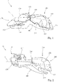
- FIG. 1 shows an exemplary signal light device 10 for a motor vehicle headlight, which signal light device 10 has a light module 100, comprising a light source 110 designed as an LED for emitting light beams and a scattering device 150, which is set up to diffuse the light beams from light source 110 essentially in the direction of a main emission direction X sprinkle, includes.
- a light module 100 comprising a light source 110 designed as an LED for emitting light beams and a scattering device 150, which is set up to diffuse the light beams from light source 110 essentially in the direction of a main emission direction X sprinkle, includes.
- the light module 100 also includes a deflection device 120, which is set up to direct the light beams from the light source 110 in the direction of the main emission direction X onto the scattering device 150 .
- the light module 100 has a collimator 130 , which is connected downstream of the light source 110 in the light propagation direction and is set up to align the light beams of the light source 110 parallel to one another.
- the collimator 130, the deflection device 120 and the scattering device 150 as a one-piece optical body made of one material, wherein the optical body can be made of polycarbonate or polymethyl methacrylate.
- the scattering device 150 has a plurality of differently oriented, planar exit surfaces for decoupling the light beams coupled into the optics body via the at least one collimator 130 essentially in the direction of the main emission direction X.
- the signal light device 10 comprises a transparent light refracting body 200, which is made of quartz glass and which has a light entry section 210 for coupling in the light beams diffusely scattered by the light module 100 and a light exit section 220 for coupling out the light beams coupled into the light refracting body 200 , and wherein the light refracting body 200 is set up in combination with the at least one light module 100 for generating a signal light distribution, for example a daytime running light.
- a transparent light refracting body 200 which is made of quartz glass and which has a light entry section 210 for coupling in the light beams diffusely scattered by the light module 100 and a light exit section 220 for coupling out the light beams coupled into the light refracting body 200 , and wherein the light refracting body 200 is set up in combination with the at least one light module 100 for generating a signal light distribution, for example a daytime running light.
- the light refraction body 200 further comprises a reflection section 230, which is set up to totally reflect light beams coupled into the light refraction body 200 , the light refraction body 200 being spatially delimited by the surfaces of the light entry section 210, the light exit section 220 and the reflection section 230 as a shell formed, the light entry section 210 is designed as a flat light entry surface, which is arranged orthogonally to the main emission direction X.
- the reflection section 230 of the light refracting body 200 can have a metal coating at least in sections.
- the light exit section 220 is formed from a plurality of differently oriented, flat exit surfaces 221 , which in their entirety essentially follow a convex basic shape, so that light beams diffusely coupled into the light refraction body 200 are coupled out via the plurality of exit surfaces 221 as a diffuse signal light distribution.
- Signaling device 10 also includes a holding body 300, on which light module 100 and one light-refracting body 200 are arranged and also fastened, light-refracting body 200 essentially resting against holding body 300 at least in sections by means of reflective section 230 or being fastened to it.
- the signaling device 10 comprises a first fastening device 400, which comprises a first engagement element 410 and a first counter-engagement element 420 , the first engagement element 410 being secured to the reflective section 230 of the light refracting body 200 is arranged and designed as a groove, the longitudinal extent of which extends substantially orthogonally to the main emission direction X.
- the first counter-engagement element 410 is arranged on the holding body 300 and is designed as a tongue, which corresponds to the groove of the light-refracting body 200 , wherein the light-refracting body 200 can be brought into a fastening state P1 by the light-refracting body 200 being placed on the holding body 300 , so that the first engagement element 410 acts on the first counter-engagement element 420 in order to secure the light-refracting body 200 in the example shown against a linear movement along an axis which runs parallel to the main emission direction X.
- the spring engages with the groove in a form-fitting manner, so that play within this connection, which can lead to small movements in the event of vibrations, is prevented.
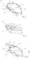
- a more detailed representation of the first fastening device 400 and the fastening state P1 is shown in FIG 3 or. figure 5 better shown.
- the signal light device 10 comprises a second fastening device 500 for further securing the light refractive body 200 on the holding body 300, wherein the second fastening device 500 comprises at least one second engagement element 510 , which is designed as at least one adhesive surface on the holding body 300 , and at least one second counter-engagement element 520 comprises, which is formed as a flat section of the reflection section 230 of the light refraction body 200 , wherein the flat section in the attachment state P1 on the holding body 300 comes to rest on the at least one adhesive surface.
- the second fastening device 500 comprises at least one second engagement element 510 , which is designed as at least one adhesive surface on the holding body 300
- at least one second counter-engagement element 520 comprises, which is formed as a flat section of the reflection section 230 of the light refraction body 200 , wherein the flat section in the attachment state P1 on the holding body 300 comes to rest on the at least one adhesive surface.
- the adhesive surface or surfaces of the second fastening device 500 are in 4 to be seen more clearly, the second fastening device 500 securing the light-refracting body 200 at least against a linear movement along an axis which is orthogonal to the main emission direction X or the course of the longitudinal extension of the groove of the first fastening device 400 .
- the signal light device 10 comprises a cover 600 and a third fastening device 700 for further securing the light refracting element 200 on the holding body 300, with the third fastening device 700 comprising a third engagement element 710 and a third counter-engagement element 720 , with the third engagement element 710 on the cover 600 is arranged, and wherein the third counter-engagement element 720 is arranged on the light exit portion 220 of the light refracting body 200 .
- the cover 600 can be brought into a fixation state P2 by the cover 600 being placed on the holding body 300 and in sections on the light refraction body 200 , so that the third engagement element 710 engages the third counter-engagement element 720 in order to prevent the light refraction body 200 from linear movement along an axis , which runs parallel to the main radiation direction X.
- the cover 600 is also fixed to the holding body 300 via a fourth fastening device or secured against movement.
- the combination of the first, second and third fastening means 400, 500, 700 secures the refractive body 200 in its fastening position P1 against any direction of movement.
- FIG. 2 shows a further example of a signal light device 10, in which what was said above also applies to this further example, wherein only the scattering device 150 of the light module 100 is embodied as a reflector, which reflector comprises a plurality of differently oriented deflection surfaces, so that light rays incident on the reflector diffuse in the direction of the Main emission direction X are deflectable.
- a further scattering device can be arranged between the light source 110 and the reflector 150 as seen in the course of the light beam.
Landscapes
- Engineering & Computer Science (AREA)
- General Engineering & Computer Science (AREA)
- Physics & Mathematics (AREA)
- Optics & Photonics (AREA)
- Microelectronics & Electronic Packaging (AREA)
- General Physics & Mathematics (AREA)
- Mechanical Engineering (AREA)
- Non-Portable Lighting Devices Or Systems Thereof (AREA)
- Lighting Device Outwards From Vehicle And Optical Signal (AREA)
Priority Applications (3)
| Application Number | Priority Date | Filing Date | Title |
|---|---|---|---|
| EP21173068.4A EP4089319B1 (fr) | 2021-05-10 | 2021-05-10 | Dispositif de signalisation pour un phare de véhicule automobile |
| KR1020220036616A KR102705148B1 (ko) | 2021-05-10 | 2022-03-24 | 자동차 헤드램프용 신호 광 장치 |
| CN202210503587.2A CN115325508A (zh) | 2021-05-10 | 2022-05-10 | 用于机动车前照灯的信号灯装置 |
Applications Claiming Priority (1)
| Application Number | Priority Date | Filing Date | Title |
|---|---|---|---|
| EP21173068.4A EP4089319B1 (fr) | 2021-05-10 | 2021-05-10 | Dispositif de signalisation pour un phare de véhicule automobile |
Publications (2)
| Publication Number | Publication Date |
|---|---|
| EP4089319A1 true EP4089319A1 (fr) | 2022-11-16 |
| EP4089319B1 EP4089319B1 (fr) | 2024-02-21 |
Family
ID=75887934
Family Applications (1)
| Application Number | Title | Priority Date | Filing Date |
|---|---|---|---|
| EP21173068.4A Active EP4089319B1 (fr) | 2021-05-10 | 2021-05-10 | Dispositif de signalisation pour un phare de véhicule automobile |
Country Status (3)
| Country | Link |
|---|---|
| EP (1) | EP4089319B1 (fr) |
| KR (1) | KR102705148B1 (fr) |
| CN (1) | CN115325508A (fr) |
Citations (9)
| Publication number | Priority date | Publication date | Assignee | Title |
|---|---|---|---|---|
| EP2237080A1 (fr) * | 2009-03-31 | 2010-10-06 | Valeo Vision | Lentille pour module d'éclairage pour projecteur de véhicule |
| EP2693105A2 (fr) * | 2012-07-31 | 2014-02-05 | Stanley Electric Co., Ltd. | Dispositif d'éclairage de véhicule |
| JP2015201278A (ja) * | 2014-04-04 | 2015-11-12 | 株式会社小糸製作所 | 車両用灯具 |
| KR20170077407A (ko) * | 2015-12-28 | 2017-07-06 | 에스엘 주식회사 | 차량용 램프 |
| DE102017117596A1 (de) * | 2016-08-08 | 2018-02-08 | Varroc Lighting Systems S.R.O. | Ein Lichtgerät für Motorfahrzeuge |
| DE102018201449A1 (de) * | 2018-01-31 | 2019-08-01 | HELLA GmbH & Co. KGaA | Optisches Dekorelement |
| DE102018104124A1 (de) * | 2018-02-23 | 2019-08-29 | Automotive Lighting Reutlingen Gmbh | Leuchtenmodul für ein Kraftfahrzeug |
| CN110630977A (zh) * | 2019-10-25 | 2019-12-31 | 马瑞利汽车零部件(芜湖)有限公司 | 一种实现均匀深邃的3d点亮效果的车灯光学系统 |
| CN209977826U (zh) * | 2019-07-25 | 2020-01-21 | 华域视觉科技(上海)有限公司 | 一种实现车灯均匀发光的光学系统 |
Family Cites Families (3)
| Publication number | Priority date | Publication date | Assignee | Title |
|---|---|---|---|---|
| DE102012218684B9 (de) * | 2012-10-12 | 2016-05-25 | Automotive Lighting Reutlingen Gmbh | Lichtmodul |
| AT517413B1 (de) * | 2015-06-29 | 2018-07-15 | Zkw Group Gmbh | Lichtleiteranordnung zur Erzeugung von zumindest einer Beleuchtungsfunktion und/oder Signalisierungsfunktion eines Kraftfahrzeugscheinwerfers |
| AT518552B1 (de) * | 2016-08-19 | 2017-11-15 | Zkw Group Gmbh | Beleuchtungseinheit für einen Kraftfahrzeugscheinwerfer zum Erzeugen von zumindest zwei Lichtverteilungen |
-
2021
- 2021-05-10 EP EP21173068.4A patent/EP4089319B1/fr active Active
-
2022
- 2022-03-24 KR KR1020220036616A patent/KR102705148B1/ko active Active
- 2022-05-10 CN CN202210503587.2A patent/CN115325508A/zh active Pending
Patent Citations (9)
| Publication number | Priority date | Publication date | Assignee | Title |
|---|---|---|---|---|
| EP2237080A1 (fr) * | 2009-03-31 | 2010-10-06 | Valeo Vision | Lentille pour module d'éclairage pour projecteur de véhicule |
| EP2693105A2 (fr) * | 2012-07-31 | 2014-02-05 | Stanley Electric Co., Ltd. | Dispositif d'éclairage de véhicule |
| JP2015201278A (ja) * | 2014-04-04 | 2015-11-12 | 株式会社小糸製作所 | 車両用灯具 |
| KR20170077407A (ko) * | 2015-12-28 | 2017-07-06 | 에스엘 주식회사 | 차량용 램프 |
| DE102017117596A1 (de) * | 2016-08-08 | 2018-02-08 | Varroc Lighting Systems S.R.O. | Ein Lichtgerät für Motorfahrzeuge |
| DE102018201449A1 (de) * | 2018-01-31 | 2019-08-01 | HELLA GmbH & Co. KGaA | Optisches Dekorelement |
| DE102018104124A1 (de) * | 2018-02-23 | 2019-08-29 | Automotive Lighting Reutlingen Gmbh | Leuchtenmodul für ein Kraftfahrzeug |
| CN209977826U (zh) * | 2019-07-25 | 2020-01-21 | 华域视觉科技(上海)有限公司 | 一种实现车灯均匀发光的光学系统 |
| CN110630977A (zh) * | 2019-10-25 | 2019-12-31 | 马瑞利汽车零部件(芜湖)有限公司 | 一种实现均匀深邃的3d点亮效果的车灯光学系统 |
Also Published As
| Publication number | Publication date |
|---|---|
| KR20220152928A (ko) | 2022-11-17 |
| CN115325508A (zh) | 2022-11-11 |
| EP4089319B1 (fr) | 2024-02-21 |
| KR102705148B1 (ko) | 2024-09-11 |
Similar Documents
| Publication | Publication Date | Title |
|---|---|---|
| DE102008048765B4 (de) | Beleuchtungsvorrichtung für Kraftfahrzeuge | |
| DE102008005488B4 (de) | Scheinwerfer für Fahrzeuge | |
| DE102012112075B4 (de) | Beleuchtungsvorrichtung für Fahrzeuge mit jeweils einem flächigen, durch eine Lichtscheibe abgedeckten und Streuelemente aufweisenden Lichtleiter an den beiden Seiten einer Fuge | |
| DE102013100557B4 (de) | Beleuchtungsvorrichtung für Fahrzeuge | |
| DE102008038668B4 (de) | Signalleuchte für Fahrzeuge, die eine Mehrzahl von parallel zueinander verlaufenden Lichtleitelementen und einen Reflektor aufweist | |
| DE102012202508B4 (de) | Lichtleitervorrichtung für eine Kraftfahrzeugleuchte | |
| EP2587120A1 (fr) | Conduit de lumière et véhicule automobile muni d'un tel conduit de lumière | |
| DE19803518A1 (de) | Stabförmiger Lichtleiter | |
| DE102013101344B4 (de) | Optisches System für eine Beleuchtungsvorrichtung für Fahrzeuge | |
| DE202021103908U1 (de) | Leuchte für ein Fahrzeug | |
| DE19646042B4 (de) | Fahrzeug-Beleuchtungseinrichtung | |
| DE102012103997A1 (de) | Beleuchtungsvorrichtung für Fahrzeuge | |
| DE19943821A1 (de) | Leuchte, insbesondere für Kraftfahrzeuge | |
| EP0933588A2 (fr) | Feu pour véhicule | |
| WO2014180813A1 (fr) | Dispositif d'éclairage pour véhicules | |
| DE102006008191B4 (de) | Leuchteneinheit für Fahrzeuge | |
| DE102012112076A1 (de) | Beleuchtungsvorrichtung für Fahrzeuge | |
| DE19904644B4 (de) | Leuchte für Fahrzeuge | |
| DE102013007856A1 (de) | Lichtleitkörper und Leuchtvorrichtung mit dem Lichtleitkörper | |
| DE102012112125A1 (de) | Beleuchtungsvorrichtung für Fahrzeuge | |
| DE102009031834A1 (de) | Balkenförmige Rückleuchte für ein Zweirad | |
| DE102009048032A1 (de) | Beleuchtungsvorrichtung für Fahrzeuge | |
| DE102012107426A1 (de) | Scheinwerfer für Fahrzeuge | |
| DE202021106229U1 (de) | Signalleuchtvorrichtung oder Beleuchtungsvorrichtung für einen Kraftfahrzeugscheinwerfer | |
| DE102015204735A1 (de) | Lichtleiterelement einer Kraftfahrzeug-Beleuchtungseinrichtung und Kraftfahrzeug-Beleuchtungseinrichtung mit einem solchen Lichtleiterelement |
Legal Events
| Date | Code | Title | Description |
|---|---|---|---|
| PUAI | Public reference made under article 153(3) epc to a published international application that has entered the european phase |
Free format text: ORIGINAL CODE: 0009012 |
|
| STAA | Information on the status of an ep patent application or granted ep patent |
Free format text: STATUS: THE APPLICATION HAS BEEN PUBLISHED |
|
| AK | Designated contracting states |
Kind code of ref document: A1 Designated state(s): AL AT BE BG CH CY CZ DE DK EE ES FI FR GB GR HR HU IE IS IT LI LT LU LV MC MK MT NL NO PL PT RO RS SE SI SK SM TR |
|
| STAA | Information on the status of an ep patent application or granted ep patent |
Free format text: STATUS: REQUEST FOR EXAMINATION WAS MADE |
|
| 17P | Request for examination filed |
Effective date: 20230511 |
|
| RBV | Designated contracting states (corrected) |
Designated state(s): AL AT BE BG CH CY CZ DE DK EE ES FI FR GB GR HR HU IE IS IT LI LT LU LV MC MK MT NL NO PL PT RO RS SE SI SK SM TR |
|
| RIC1 | Information provided on ipc code assigned before grant |
Ipc: F21W 103/20 20180101ALN20231016BHEP Ipc: F21W 103/55 20180101ALN20231016BHEP Ipc: G02B 19/00 20060101ALI20231016BHEP Ipc: G02B 3/00 20060101ALI20231016BHEP Ipc: F21S 43/14 20180101ALI20231016BHEP Ipc: F21S 43/40 20180101ALI20231016BHEP Ipc: F21S 43/31 20180101ALI20231016BHEP Ipc: F21S 43/20 20180101AFI20231016BHEP |
|
| RIC1 | Information provided on ipc code assigned before grant |
Ipc: F21W 103/20 20180101ALN20231108BHEP Ipc: F21W 103/55 20180101ALN20231108BHEP Ipc: G02B 19/00 20060101ALI20231108BHEP Ipc: G02B 3/00 20060101ALI20231108BHEP Ipc: F21S 43/14 20180101ALI20231108BHEP Ipc: F21S 43/40 20180101ALI20231108BHEP Ipc: F21S 43/31 20180101ALI20231108BHEP Ipc: F21S 43/20 20180101AFI20231108BHEP |
|
| GRAP | Despatch of communication of intention to grant a patent |
Free format text: ORIGINAL CODE: EPIDOSNIGR1 |
|
| STAA | Information on the status of an ep patent application or granted ep patent |
Free format text: STATUS: GRANT OF PATENT IS INTENDED |
|
| GRAS | Grant fee paid |
Free format text: ORIGINAL CODE: EPIDOSNIGR3 |
|
| INTG | Intention to grant announced |
Effective date: 20231222 |
|
| GRAA | (expected) grant |
Free format text: ORIGINAL CODE: 0009210 |
|
| STAA | Information on the status of an ep patent application or granted ep patent |
Free format text: STATUS: THE PATENT HAS BEEN GRANTED |
|
| AK | Designated contracting states |
Kind code of ref document: B1 Designated state(s): AL AT BE BG CH CY CZ DE DK EE ES FI FR GB GR HR HU IE IS IT LI LT LU LV MC MK MT NL NO PL PT RO RS SE SI SK SM TR |
|
| REG | Reference to a national code |
Ref country code: GB Ref legal event code: FG4D Free format text: NOT ENGLISH |
|
| REG | Reference to a national code |
Ref country code: CH Ref legal event code: EP |
|
| REG | Reference to a national code |
Ref country code: DE Ref legal event code: R096 Ref document number: 502021002728 Country of ref document: DE |
|
| REG | Reference to a national code |
Ref country code: IE Ref legal event code: FG4D Free format text: LANGUAGE OF EP DOCUMENT: GERMAN |
|
| REG | Reference to a national code |
Ref country code: LT Ref legal event code: MG9D |
|
| P01 | Opt-out of the competence of the unified patent court (upc) registered |
Effective date: 20240506 |
|
| REG | Reference to a national code |
Ref country code: NL Ref legal event code: MP Effective date: 20240221 |
|
| PG25 | Lapsed in a contracting state [announced via postgrant information from national office to epo] |
Ref country code: IS Free format text: LAPSE BECAUSE OF FAILURE TO SUBMIT A TRANSLATION OF THE DESCRIPTION OR TO PAY THE FEE WITHIN THE PRESCRIBED TIME-LIMIT Effective date: 20240621 |
|
| PG25 | Lapsed in a contracting state [announced via postgrant information from national office to epo] |
Ref country code: LT Free format text: LAPSE BECAUSE OF FAILURE TO SUBMIT A TRANSLATION OF THE DESCRIPTION OR TO PAY THE FEE WITHIN THE PRESCRIBED TIME-LIMIT Effective date: 20240221 |
|
| PG25 | Lapsed in a contracting state [announced via postgrant information from national office to epo] |
Ref country code: GR Free format text: LAPSE BECAUSE OF FAILURE TO SUBMIT A TRANSLATION OF THE DESCRIPTION OR TO PAY THE FEE WITHIN THE PRESCRIBED TIME-LIMIT Effective date: 20240522 |
|
| PG25 | Lapsed in a contracting state [announced via postgrant information from national office to epo] |
Ref country code: RS Free format text: LAPSE BECAUSE OF FAILURE TO SUBMIT A TRANSLATION OF THE DESCRIPTION OR TO PAY THE FEE WITHIN THE PRESCRIBED TIME-LIMIT Effective date: 20240521 Ref country code: HR Free format text: LAPSE BECAUSE OF FAILURE TO SUBMIT A TRANSLATION OF THE DESCRIPTION OR TO PAY THE FEE WITHIN THE PRESCRIBED TIME-LIMIT Effective date: 20240221 Ref country code: NL Free format text: LAPSE BECAUSE OF FAILURE TO SUBMIT A TRANSLATION OF THE DESCRIPTION OR TO PAY THE FEE WITHIN THE PRESCRIBED TIME-LIMIT Effective date: 20240221 |
|
| PG25 | Lapsed in a contracting state [announced via postgrant information from national office to epo] |
Ref country code: ES Free format text: LAPSE BECAUSE OF FAILURE TO SUBMIT A TRANSLATION OF THE DESCRIPTION OR TO PAY THE FEE WITHIN THE PRESCRIBED TIME-LIMIT Effective date: 20240221 |
|
| PG25 | Lapsed in a contracting state [announced via postgrant information from national office to epo] |
Ref country code: RS Free format text: LAPSE BECAUSE OF FAILURE TO SUBMIT A TRANSLATION OF THE DESCRIPTION OR TO PAY THE FEE WITHIN THE PRESCRIBED TIME-LIMIT Effective date: 20240521 Ref country code: NO Free format text: LAPSE BECAUSE OF FAILURE TO SUBMIT A TRANSLATION OF THE DESCRIPTION OR TO PAY THE FEE WITHIN THE PRESCRIBED TIME-LIMIT Effective date: 20240521 Ref country code: NL Free format text: LAPSE BECAUSE OF FAILURE TO SUBMIT A TRANSLATION OF THE DESCRIPTION OR TO PAY THE FEE WITHIN THE PRESCRIBED TIME-LIMIT Effective date: 20240221 Ref country code: LT Free format text: LAPSE BECAUSE OF FAILURE TO SUBMIT A TRANSLATION OF THE DESCRIPTION OR TO PAY THE FEE WITHIN THE PRESCRIBED TIME-LIMIT Effective date: 20240221 Ref country code: IS Free format text: LAPSE BECAUSE OF FAILURE TO SUBMIT A TRANSLATION OF THE DESCRIPTION OR TO PAY THE FEE WITHIN THE PRESCRIBED TIME-LIMIT Effective date: 20240621 Ref country code: HR Free format text: LAPSE BECAUSE OF FAILURE TO SUBMIT A TRANSLATION OF THE DESCRIPTION OR TO PAY THE FEE WITHIN THE PRESCRIBED TIME-LIMIT Effective date: 20240221 Ref country code: GR Free format text: LAPSE BECAUSE OF FAILURE TO SUBMIT A TRANSLATION OF THE DESCRIPTION OR TO PAY THE FEE WITHIN THE PRESCRIBED TIME-LIMIT Effective date: 20240522 Ref country code: FI Free format text: LAPSE BECAUSE OF FAILURE TO SUBMIT A TRANSLATION OF THE DESCRIPTION OR TO PAY THE FEE WITHIN THE PRESCRIBED TIME-LIMIT Effective date: 20240221 Ref country code: ES Free format text: LAPSE BECAUSE OF FAILURE TO SUBMIT A TRANSLATION OF THE DESCRIPTION OR TO PAY THE FEE WITHIN THE PRESCRIBED TIME-LIMIT Effective date: 20240221 Ref country code: BG Free format text: LAPSE BECAUSE OF FAILURE TO SUBMIT A TRANSLATION OF THE DESCRIPTION OR TO PAY THE FEE WITHIN THE PRESCRIBED TIME-LIMIT Effective date: 20240221 |
|
| PG25 | Lapsed in a contracting state [announced via postgrant information from national office to epo] |
Ref country code: PL Free format text: LAPSE BECAUSE OF FAILURE TO SUBMIT A TRANSLATION OF THE DESCRIPTION OR TO PAY THE FEE WITHIN THE PRESCRIBED TIME-LIMIT Effective date: 20240221 Ref country code: PT Free format text: LAPSE BECAUSE OF FAILURE TO SUBMIT A TRANSLATION OF THE DESCRIPTION OR TO PAY THE FEE WITHIN THE PRESCRIBED TIME-LIMIT Effective date: 20240621 |
|
| PG25 | Lapsed in a contracting state [announced via postgrant information from national office to epo] |
Ref country code: SE Free format text: LAPSE BECAUSE OF FAILURE TO SUBMIT A TRANSLATION OF THE DESCRIPTION OR TO PAY THE FEE WITHIN THE PRESCRIBED TIME-LIMIT Effective date: 20240221 Ref country code: PT Free format text: LAPSE BECAUSE OF FAILURE TO SUBMIT A TRANSLATION OF THE DESCRIPTION OR TO PAY THE FEE WITHIN THE PRESCRIBED TIME-LIMIT Effective date: 20240621 Ref country code: PL Free format text: LAPSE BECAUSE OF FAILURE TO SUBMIT A TRANSLATION OF THE DESCRIPTION OR TO PAY THE FEE WITHIN THE PRESCRIBED TIME-LIMIT Effective date: 20240221 Ref country code: LV Free format text: LAPSE BECAUSE OF FAILURE TO SUBMIT A TRANSLATION OF THE DESCRIPTION OR TO PAY THE FEE WITHIN THE PRESCRIBED TIME-LIMIT Effective date: 20240221 |
|
| PG25 | Lapsed in a contracting state [announced via postgrant information from national office to epo] |
Ref country code: DK Free format text: LAPSE BECAUSE OF FAILURE TO SUBMIT A TRANSLATION OF THE DESCRIPTION OR TO PAY THE FEE WITHIN THE PRESCRIBED TIME-LIMIT Effective date: 20240221 |
|
| PG25 | Lapsed in a contracting state [announced via postgrant information from national office to epo] |
Ref country code: SM Free format text: LAPSE BECAUSE OF FAILURE TO SUBMIT A TRANSLATION OF THE DESCRIPTION OR TO PAY THE FEE WITHIN THE PRESCRIBED TIME-LIMIT Effective date: 20240221 |
|
| PG25 | Lapsed in a contracting state [announced via postgrant information from national office to epo] |
Ref country code: EE Free format text: LAPSE BECAUSE OF FAILURE TO SUBMIT A TRANSLATION OF THE DESCRIPTION OR TO PAY THE FEE WITHIN THE PRESCRIBED TIME-LIMIT Effective date: 20240221 Ref country code: CZ Free format text: LAPSE BECAUSE OF FAILURE TO SUBMIT A TRANSLATION OF THE DESCRIPTION OR TO PAY THE FEE WITHIN THE PRESCRIBED TIME-LIMIT Effective date: 20240221 |
|
| PG25 | Lapsed in a contracting state [announced via postgrant information from national office to epo] |
Ref country code: SK Free format text: LAPSE BECAUSE OF FAILURE TO SUBMIT A TRANSLATION OF THE DESCRIPTION OR TO PAY THE FEE WITHIN THE PRESCRIBED TIME-LIMIT Effective date: 20240221 |
|
| PG25 | Lapsed in a contracting state [announced via postgrant information from national office to epo] |
Ref country code: SM Free format text: LAPSE BECAUSE OF FAILURE TO SUBMIT A TRANSLATION OF THE DESCRIPTION OR TO PAY THE FEE WITHIN THE PRESCRIBED TIME-LIMIT Effective date: 20240221 Ref country code: SK Free format text: LAPSE BECAUSE OF FAILURE TO SUBMIT A TRANSLATION OF THE DESCRIPTION OR TO PAY THE FEE WITHIN THE PRESCRIBED TIME-LIMIT Effective date: 20240221 Ref country code: RO Free format text: LAPSE BECAUSE OF FAILURE TO SUBMIT A TRANSLATION OF THE DESCRIPTION OR TO PAY THE FEE WITHIN THE PRESCRIBED TIME-LIMIT Effective date: 20240221 Ref country code: EE Free format text: LAPSE BECAUSE OF FAILURE TO SUBMIT A TRANSLATION OF THE DESCRIPTION OR TO PAY THE FEE WITHIN THE PRESCRIBED TIME-LIMIT Effective date: 20240221 Ref country code: DK Free format text: LAPSE BECAUSE OF FAILURE TO SUBMIT A TRANSLATION OF THE DESCRIPTION OR TO PAY THE FEE WITHIN THE PRESCRIBED TIME-LIMIT Effective date: 20240221 Ref country code: CZ Free format text: LAPSE BECAUSE OF FAILURE TO SUBMIT A TRANSLATION OF THE DESCRIPTION OR TO PAY THE FEE WITHIN THE PRESCRIBED TIME-LIMIT Effective date: 20240221 |
|
| REG | Reference to a national code |
Ref country code: DE Ref legal event code: R097 Ref document number: 502021002728 Country of ref document: DE |
|
| PG25 | Lapsed in a contracting state [announced via postgrant information from national office to epo] |
Ref country code: IT Free format text: LAPSE BECAUSE OF FAILURE TO SUBMIT A TRANSLATION OF THE DESCRIPTION OR TO PAY THE FEE WITHIN THE PRESCRIBED TIME-LIMIT Effective date: 20240221 |
|
| PLBE | No opposition filed within time limit |
Free format text: ORIGINAL CODE: 0009261 |
|
| STAA | Information on the status of an ep patent application or granted ep patent |
Free format text: STATUS: NO OPPOSITION FILED WITHIN TIME LIMIT |
|
| REG | Reference to a national code |
Ref country code: CH Ref legal event code: PL |
|
| PG25 | Lapsed in a contracting state [announced via postgrant information from national office to epo] |
Ref country code: IT Free format text: LAPSE BECAUSE OF FAILURE TO SUBMIT A TRANSLATION OF THE DESCRIPTION OR TO PAY THE FEE WITHIN THE PRESCRIBED TIME-LIMIT Effective date: 20240221 |
|
| PG25 | Lapsed in a contracting state [announced via postgrant information from national office to epo] |
Ref country code: MC Free format text: LAPSE BECAUSE OF FAILURE TO SUBMIT A TRANSLATION OF THE DESCRIPTION OR TO PAY THE FEE WITHIN THE PRESCRIBED TIME-LIMIT Effective date: 20240221 |
|
| PG25 | Lapsed in a contracting state [announced via postgrant information from national office to epo] |
Ref country code: LU Free format text: LAPSE BECAUSE OF NON-PAYMENT OF DUE FEES Effective date: 20240510 |
|
| 26N | No opposition filed |
Effective date: 20241122 |
|
| PG25 | Lapsed in a contracting state [announced via postgrant information from national office to epo] |
Ref country code: MC Free format text: LAPSE BECAUSE OF FAILURE TO SUBMIT A TRANSLATION OF THE DESCRIPTION OR TO PAY THE FEE WITHIN THE PRESCRIBED TIME-LIMIT Effective date: 20240221 Ref country code: LU Free format text: LAPSE BECAUSE OF NON-PAYMENT OF DUE FEES Effective date: 20240510 Ref country code: CH Free format text: LAPSE BECAUSE OF NON-PAYMENT OF DUE FEES Effective date: 20240531 |
|
| REG | Reference to a national code |
Ref country code: BE Ref legal event code: MM Effective date: 20240531 |
|
| PG25 | Lapsed in a contracting state [announced via postgrant information from national office to epo] |
Ref country code: IE Free format text: LAPSE BECAUSE OF NON-PAYMENT OF DUE FEES Effective date: 20240510 |
|
| PG25 | Lapsed in a contracting state [announced via postgrant information from national office to epo] |
Ref country code: SI Free format text: LAPSE BECAUSE OF FAILURE TO SUBMIT A TRANSLATION OF THE DESCRIPTION OR TO PAY THE FEE WITHIN THE PRESCRIBED TIME-LIMIT Effective date: 20240221 Ref country code: BE Free format text: LAPSE BECAUSE OF NON-PAYMENT OF DUE FEES Effective date: 20240531 |
|
| PGFP | Annual fee paid to national office [announced via postgrant information from national office to epo] |
Ref country code: DE Payment date: 20250521 Year of fee payment: 5 |
|
| PGFP | Annual fee paid to national office [announced via postgrant information from national office to epo] |
Ref country code: FR Payment date: 20250528 Year of fee payment: 5 |
|
| PGFP | Annual fee paid to national office [announced via postgrant information from national office to epo] |
Ref country code: AT Payment date: 20250721 Year of fee payment: 5 |
|
| PG25 | Lapsed in a contracting state [announced via postgrant information from national office to epo] |
Ref country code: CY Free format text: LAPSE BECAUSE OF FAILURE TO SUBMIT A TRANSLATION OF THE DESCRIPTION OR TO PAY THE FEE WITHIN THE PRESCRIBED TIME-LIMIT; INVALID AB INITIO Effective date: 20210510 |
|
| PG25 | Lapsed in a contracting state [announced via postgrant information from national office to epo] |
Ref country code: HU Free format text: LAPSE BECAUSE OF FAILURE TO SUBMIT A TRANSLATION OF THE DESCRIPTION OR TO PAY THE FEE WITHIN THE PRESCRIBED TIME-LIMIT; INVALID AB INITIO Effective date: 20210510 |
|
| GBPC | Gb: european patent ceased through non-payment of renewal fee |
Effective date: 20250510 |
|
| PG25 | Lapsed in a contracting state [announced via postgrant information from national office to epo] |
Ref country code: GB Free format text: LAPSE BECAUSE OF NON-PAYMENT OF DUE FEES Effective date: 20250510 |