EP4089636A1 - Vorrichtung, verfahren und computerprogrammprodukt zur erzeugung von ortsinformationen eines objekts in einer szene - Google Patents
Vorrichtung, verfahren und computerprogrammprodukt zur erzeugung von ortsinformationen eines objekts in einer szene Download PDFInfo
- Publication number
- EP4089636A1 EP4089636A1 EP22171505.5A EP22171505A EP4089636A1 EP 4089636 A1 EP4089636 A1 EP 4089636A1 EP 22171505 A EP22171505 A EP 22171505A EP 4089636 A1 EP4089636 A1 EP 4089636A1
- Authority
- EP
- European Patent Office
- Prior art keywords
- scene
- location information
- location
- ball
- properties
- Prior art date
- Legal status (The legal status is an assumption and is not a legal conclusion. Google has not performed a legal analysis and makes no representation as to the accuracy of the status listed.)
- Pending
Links
Images


Classifications
-
- G—PHYSICS
- G06—COMPUTING OR CALCULATING; COUNTING
- G06T—IMAGE DATA PROCESSING OR GENERATION, IN GENERAL
- G06T7/00—Image analysis
- G06T7/20—Analysis of motion
- G06T7/246—Analysis of motion using feature-based methods, e.g. the tracking of corners or segments
-
- G—PHYSICS
- G06—COMPUTING OR CALCULATING; COUNTING
- G06T—IMAGE DATA PROCESSING OR GENERATION, IN GENERAL
- G06T7/00—Image analysis
- G06T7/20—Analysis of motion
-
- G—PHYSICS
- G06—COMPUTING OR CALCULATING; COUNTING
- G06T—IMAGE DATA PROCESSING OR GENERATION, IN GENERAL
- G06T7/00—Image analysis
- G06T7/70—Determining position or orientation of objects or cameras
-
- G—PHYSICS
- G06—COMPUTING OR CALCULATING; COUNTING
- G06T—IMAGE DATA PROCESSING OR GENERATION, IN GENERAL
- G06T7/00—Image analysis
- G06T7/70—Determining position or orientation of objects or cameras
- G06T7/77—Determining position or orientation of objects or cameras using statistical methods
-
- G—PHYSICS
- G06—COMPUTING OR CALCULATING; COUNTING
- G06T—IMAGE DATA PROCESSING OR GENERATION, IN GENERAL
- G06T7/00—Image analysis
- G06T7/97—Determining parameters from multiple pictures
-
- G—PHYSICS
- G06—COMPUTING OR CALCULATING; COUNTING
- G06V—IMAGE OR VIDEO RECOGNITION OR UNDERSTANDING
- G06V10/00—Arrangements for image or video recognition or understanding
- G06V10/20—Image preprocessing
- G06V10/25—Determination of region of interest [ROI] or a volume of interest [VOI]
-
- G—PHYSICS
- G06—COMPUTING OR CALCULATING; COUNTING
- G06T—IMAGE DATA PROCESSING OR GENERATION, IN GENERAL
- G06T2207/00—Indexing scheme for image analysis or image enhancement
- G06T2207/10—Image acquisition modality
- G06T2207/10016—Video; Image sequence
-
- G—PHYSICS
- G06—COMPUTING OR CALCULATING; COUNTING
- G06T—IMAGE DATA PROCESSING OR GENERATION, IN GENERAL
- G06T2207/00—Indexing scheme for image analysis or image enhancement
- G06T2207/30—Subject of image; Context of image processing
- G06T2207/30221—Sports video; Sports image
-
- G—PHYSICS
- G06—COMPUTING OR CALCULATING; COUNTING
- G06T—IMAGE DATA PROCESSING OR GENERATION, IN GENERAL
- G06T2207/00—Indexing scheme for image analysis or image enhancement
- G06T2207/30—Subject of image; Context of image processing
- G06T2207/30221—Sports video; Sports image
- G06T2207/30224—Ball; Puck
-
- G—PHYSICS
- G06—COMPUTING OR CALCULATING; COUNTING
- G06T—IMAGE DATA PROCESSING OR GENERATION, IN GENERAL
- G06T2207/00—Indexing scheme for image analysis or image enhancement
- G06T2207/30—Subject of image; Context of image processing
- G06T2207/30241—Trajectory
-
- G—PHYSICS
- G06—COMPUTING OR CALCULATING; COUNTING
- G06V—IMAGE OR VIDEO RECOGNITION OR UNDERSTANDING
- G06V2201/00—Indexing scheme relating to image or video recognition or understanding
- G06V2201/07—Target detection
Definitions
- the present invention relates to an apparatus, method and computer program product for generating location information of an object in a scene.
- certain events are often complex, comprising a number of different objects. That is, it can be difficult in order to reliably analyse a specific object within the event (or scene) owing to the number of different objects that are present. This makes it more difficult to obtain certain information regarding these objects from images of the event.
- an apparatus for generating location information of an object in a scene comprising circuitry configured to: acquire image data of a scene from an image capture device; acquire predicted location information of an object in the scene indicative of a region of the scene in which the object is predicted to be located at a given time; detect one or more properties of the object from the image data, the properties of the object indicative of an observed location of the object in the scene; and generate location information of the object in the scene using the predicted location information and the one of more properties of the object.
- a method of generating location information of an object in a scene comprising: acquiring image data of a scene from an image capture device; acquiring predicted location information of an object in the scene indicative of a region of the scene in which the object is predicted to be located at a given time; detecting one or more properties of the object from the image data, the properties of the object indicative of an observed location of the object in the scene; and generating location information of the object in the scene using the predicted location information and the one of more properties of the object.
- a computer program product comprising instructions which, when the instructions are implemented by a computer, cause the computer to perform a method of generating location information of an object in a scene
- the method comprising: acquiring image data of a scene from an image capture device; acquiring predicted location information of an object in the scene indicative of a region of the scene in which the object is predicted to be located at a given time; detecting one or more properties of the object from the image data, the properties of the object indicative of an observed location of the object in the scene; and generating location information of the object in the scene using the predicted location information and the one of more properties of the object.
- the location of an object within a scene can be efficiently and reliably determined from images obtained from a simple image capture system (such as a single image capture device).
- the location of the object in the images of the scene can be further analysed in order to determine further additional information regarding the object.
- the additional information which can be determined by embodiments of the disclosure may be particularly advantageous when used for training in order to improve the performance of a physical skill or performance of a physical task.
- an apparatus 1000 according to embodiments of the disclosure is shown.
- an apparatus 1000 according to embodiments of the disclosure is a computer device such as a personal computer or a terminal connected to a server.
- the apparatus may also be a server.
- the apparatus 1000 is controlled using a microprocessor or other processing circuitry 1002.
- the processing circuitry 1002 may be a microprocessor carrying out computer instructions or may be an Application Specific Integrated Circuit.
- the computer instructions are stored on storage medium 1004, which may be a magnetically readable medium, optically readable medium or solid-state type circuitry.
- the storage medium 1004 may be integrated into the apparatus 1000 (as shown) or, alternatively, may be separate to the apparatus 1000 and connected thereto using either a wired or a wireless connection.
- the computer instructions may be embodied as computer software that contains computer readable code which, when loaded onto the processor circuitry 1002, configures the processor circuitry 1002 to perform a method according to embodiments of the disclosure.
- the user input 1006 may be a touch screen or maybe a mouse or stylist type input device.
- the user input 1006 may also be a keyboard or any combination of these devices.
- the user input 1006 may also be configured to receive audio input such as voice instructions or the like. The present disclosure is not particularly limited in this respect.
- a network connection 1008 is also coupled to the processor circuitry 1002.
- the network connection 1008 may be a connection to a Local Area Network or a Wide Area Network such as the Internet or a Virtual Private Network or the like.
- the network connection 1008 may be connected to external servers or devices allowing the processor circuitry 1002 to communicate with the other servers or devices in order to obtain relevant data or provide relevant data to these other servers or devices.
- the network connection 1008 may be located behind a firewall or some other form of network security. Indeed, network connection 1008 may be used to perform encrypted communication with a connected device.
- a display device 1010 is coupled to the processing circuitry 1002, and is a display device 1010.
- the display device although shown integrated into the apparatus 1000, may additionally be separate to the apparatus 1000 and may be a monitor or some kind of device allowing the user to visualise the operation of the system.
- the display device 1010 may be a printer or some other device allowing relevant information generated by the apparatus 1000 to be viewed by the user or by a third party.
- apparatus 1000 may be able to output data to a number of display devices 1010 simultaneously.
- FIG 2 an example situation to which embodiments of the present disclosure may be applied is illustrated.
- the sporting event may be a sporting event such as a cricket match, baseball match, tennis match or the like.
- the example of Figure 2 of the present disclosure will be described with reference to a cricket match.
- a player 2000 is playing the game of cricket.
- the player 2000 plays the game of cricket by bowling a ball towards a target (i.e. the cricket stumps).
- a second player also plays the game by attempting to hit the ball with an object such as a bat such that the ball does not hit the target (i.e. the cricket stumps).
- the ball follows a trajectory such as that illustrated as PI in Figure 2 .
- the player 2000 may bowl the ball 2002 towards the target such that the ball 2002 bounces (i.e. hits the ground) a certain distance D in front of the target (that is, the cricket stumps) such that the ball bounces off the ground towards the target 2004.
- This additional information may include the location of the ball, the speed of the ball, the spin applied to the ball, a projected path of the ball or the like.
- This additional information may be particularly useful for a person (such as a coach or the like) who wishes to use the additional information in order to assist in training the player such that they can improve the player's performance in the sport.
- this additional information may be particularly useful for an adjudicator, referee or umpire who is tasked with determining whether or not a player who plays the sport (such as cricket) follows certain rules and restrictions of the game. For example, it may be necessary to determine whether or not the ball would have reached the target if it had not been illegitimately impeded by an object other than a bat of a second player (e.g. batsman).
- the environment in which the sporting event is played is a three-dimensional real world environment. Therefore, the ball has a three dimensional location in the sporting environment which changes overtime.
- a plurality of image capture devices may be provided at predetermined locations around the sporting environment to capture a series of high quality images of the ball as it passes through the environment once it has been bowled by the player.
- six or more high performance image capture devices may be provided a predetermined locations around the sporting environment to capture images of the ball from different angles and locations.
- the images from the plurality of image capture devices may then be used in order to triangulate a location of the ball within the sporting environment.
- a known system such as this may be used by a professional television broadcaster or the like in order to provide additional information to supplement and support a video broadcast.
- the known system requires a complex image capture system comprising a plurality of high performance image capture devices arranged at predetermined locations around the sporting environment. Therefore, while such a known system can be used in order to provide certain additional information regarding an object such as the ball as it passes through the environment at professional sporting events, the application of such a system to events other than these professional sporting events is very limited. That is, the hardware restrictions and requirements of this known system are prohibitive in the application of such technology to events other than these large scale professional sporting events (such as amateur sporting events, training sporting events, social sporting events or the like).
- an apparatus, method and computer program product are provided which enable the location of an object within a scene to be efficiently and reliably determined from images obtained from a simple image capture system such as a single image capture device.
- the apparatus 3000 may be implemented as an apparatus such as apparatus 1000 as described with reference to Figure 1 of the present disclosure.
- the apparatus comprises an acquiring unit 3002, an acquiring unit 3004, a detecting unit 3006 and a generating unit 3008.
- the acquiring unit 3002 of apparatus 3000 is configured to acquire image data of a scene from an image capture device.
- the acquiring unit 3002 of apparatus 3000 may be configured in order to acquire the image data of the scene from a single image capture device which is configured in order to capture image data of the scene.
- the acquiring unit 3004 of apparatus 3000 is configured to acquire predicted location information of an object in the scene indicative of a region of the scene in which the object is predicted to be located at a given time.
- the detecting unit 3006 of apparatus 3000 is configured to detect one or more properties of the object from the image data, the properties of the object indicative of an observed location of the object in the scene.
- the observed location of the object in the scene may be the location of a ball once it has been bowled by player 2000 for example.
- generating unit 3008 is configured to generate location information of the object in the scene using the predicted location information and the one of more properties of the object.
- the location information of the object which is generated by the generating unit 3008 may comprise a three dimensional path of the object through the scene, for example.
- apparatus 3000 is configured to efficiently and reliably generate location information of an object in a scene from a single image capture device which can thus be used in order to provide additional information regarding the object.
- apparatus 3000 comprises an acquiring unit 3002 which is configured to acquire image data of a scene from an image capture device.
- FIG. 2 the example sporting event which is illustrated in Figure 2 of the present disclosure.
- this example sporting event e.g. a cricket match
- a player 2000 has bowled a ball 2002 towards the target 2004.
- the sporting event illustrated in Figure 2 of the present disclosure may not be a professional sporting event. Rather, the sporting event may, for example, be an amateur sporting events, training sporting events, social sporting events or the like. Alternatively, the sporting event may be a professional sporting event where the availability of complex image capture systems is restricted.
- the embodiments of the disclosure enable the use of simple image capture systems (such as a single image capture device) in order to generate location information of an object (such as the ball) and acquire additional information regarding that object which can be used for further analysis, training or the like.
- simple image capture systems such as a single image capture device
- an image capture device 2006 is provided which is configured to capture images of the sporting event (i.e. the scene).
- the image capture device 2006 may be any type of image capture device which is able to capture images of the sporting event.
- the images which are captured by the image capture device may be a series of single or individual images of the scene.
- the images captured by the image capture device 2006 may form an image sequence (such as a video of the scene).
- the image capture device 2006 may capture a plurality of images of the scene.
- the coach 2006 therefore operates the image capture device 2006 in order to capture images of the player 2000 bowling the ball 2002 towards the target.
- a referee or umpire may be watching the player 2000 playing the sport.
- the referee (or umpire in the game of cricket) may be watching the player 2000 play the sport with a view to ensuring that the player plays the sport in accordance with the predetermined rules of that sport. If the player does not play within these rules, then the umpire may declare that foul play has occurred. Accordingly, the player (or the team for which the player plays) may be penalised. In this manner, the umpire has the role of an adjudicator of the sporting event.
- the umpire may be provided with the image capture device 2006.
- the image capture device 2006 may obtain images of the sporting event from the same location as the umpire. That is, the umpire may operate the image capture device in order to capture images of the player 2000 bowling the ball 2002 towards the target. It will be appreciated that the umpire is typically positioned close to the player 2000 such that the umpire can see whether the player follows the rules of the sporting event. Therefore, when the image capture device is operated by the umpire, the image capture device 2006 may have good visibility of the ball 2002 as it is bowled by the player 2000 towards the target. That is, owing to the unique location of the umpire within the sporting environment, the image capture device operated by the umpire may capture image data (e.g. image frames) with very good visibility of the initial action (e.g. as the ball is released by the player 2000 when being bowled towards the target). This image data of the initial action may be particularly advantageous when used by apparatus 3000 to generate location information of the object in the scene.
- image data e.g. image frames
- the image capture device 2006 may be a dedicated image capture device (such as a camera or the like). However, in other examples, the image capture device may be an image capture device which is integrated into a different electronic device.
- the image capture device 2006 may be an image capture device which is part of a user electronic device such as a portable electronic device (including, for example, a smartphone or tablet or the like).
- the image capture device may be releasably attached to the user, which enables the user to operate the image capture device without holding the device.
- the image capture device may be a device such as a body camera or the like.
- the coach (or umpire) 2008 may operate a personal portable electronic device (such as a smartphone) in order to capture images of the player 2000 as they bowl the ball towards the target.
- a personal portable electronic device such as a smartphone
- the image capture device may be controlled by the apparatus 3000 in order to capture the image or images of the scene.
- the type of images which are obtained by the image capture device 2006 in accordance with the present disclosure are not particularly limited.
- the images captured by the image capture device 2006 may be high resolution images of the scene.
- the present disclosure is not particularly limited in this regard. That is, the image need not be a high resolution image of the scene and may be a lower resolution image of the scene.
- the number of images which are captured by the image capture device 2006 of the scene is not particularly limited.
- the image capture device may capture a small number of images of the scene.
- the time at which these images are captured as the ball moves towards the target is not particularly limited.
- the images captured by the image capture device may include images of the ball at the start of its trajectory (i.e. as it is released from the hand of the player) and one or more further images as the ball approaches the target.
- the images captured by the image capture device include a number of images of the ball both before the ball hits the ground and after the ball hits the ground.
- the present disclosure is not particularly limited in this regard.
- Figure 4 of the present disclosure illustrates a series of images captured by an image capture device in accordance with embodiments of the disclosure. These images may be images captured using image capture device 2006 illustrated in Figure 2 of the present disclosure, for example.
- the images illustrated in Figure 4 of the present disclosure include a first image 11, a second image 12 and a third image 13.
- Each of the images 11, 12 and 13 comprise the player 2000 and the ball 2002.
- a number of additional features or objects may also be included in these images (such as the target 2004, for example).
- the first image I1 is an image captured at a first time T1.
- time T1 is a time after the ball 2002 has been bowled by the player 2000.
- the second image is an image captured at a second time T2 after the time of capture T1 of the first image 11.
- the third image is an image captured at a third time T3 after the time of capture T2 of the second image 12.
- the ball in the first image I1, the ball is at an early stage of its trajectory having been bowled by the player 2000. As such, in image I1, the ball 2002 appears close to the player 2000.
- the second image 12 is an image captured after image I1 and the ball 2002 has therefore progressed along its trajectory towards the target. In image 13, the ball 2002 is further along its trajectory and is close to the ground.
- the series of images I1, 12 and 13 therefore show, in discrete steps, a two dimensional representation of the ball once it has been bowled by the player 2000.
- the image capture device 2006 need not be located at a predetermined location within the environment. That is, the images captured by the image capture device 2006 can be captured from any location within the environment. In fact, the image capture device 2006 does not need to be calibrated for a given location as the apparatus 3000 may, optionally, be configured to perform calibration on the images which have been acquired by the image capture device when generating the location information of the object in the scene.
- player 2000 is playing a sport such as tennis, cricket or the like.
- the player 2000 bowls the ball 2002 towards a target (i.e. cricket stumps).
- the coach 2008 operates an image capture device 2006 in order to capture images of the scene.
- the field of view I of the image capture device 2006 is shown in Figure 2 .
- This field of view encompasses the player 2000 and the target 2004. Therefore, the target 2004 appears in the images which are captured of the scene by the image capture device.
- the target i.e. the cricket stumps
- the target have a predetermined size and configuration (that is, for example, all cricket stumps must conform to a standard height and location on the pitch).
- the appearance of the target within the images can be used by apparatus 3000 in order to perform a calibration of the images captured by the image capture device.
- calibration of the image can be performed using information regarding any known object or feature which appears in the images captured by the image capture device depending on the situation.
- the location and orientation of features such as the lines (e.g. the baseline) which defines the court can be used by apparatus 3000 for calibration of the images.
- the coach 2008 may perform a certain calibration operation before capturing the images of the sporting event. That is, the coach 2008 may provide information regarding the location of the image capture device at time of image capture. Alternatively, the coach 2008 may operate the image capture device 2006 in order to capture one or more calibration images of the scene.
- the acquiring unit 3002 of apparatus 3000 is configured to acquire image data from the image capture device 2006.
- the acquiring unit 3002 of apparatus 3000 may communicate with the image capture device 2006 in order to acquire image data of the image or images which have been captured. This may be performed by any wired or wireless communication.
- the image capture device 2006 is integrated as part of a user electronic device (such as a smartphone or tablet) the acquiring unit 3002 may be configured to acquire image data over a network such as the internet or the like. This may include, for example, uploading the images which have been captured by the image capture device 2006 to a server for processing by apparatus 3000.
- the image data may be acquired from the image capture device 2006 in a substantially real time environment (i.e. as the images are captured by the image capture device).
- the acquiring unit 3002 may acquire a live stream of image data from the image capture device 2006.
- the acquiring unit 3002 may acquire image data which has previously been captured by the image capture device 2006.
- the image capture device 2006 may capture images of the scene and store those images in a storage device. Then, the acquiring unit 3002 may acquire the images from the storage device when it is desired that apparatus 3000 performs processing on the images which have been captured by the image capture device 2006.
- the acquiring unit 3002 may be implemented as a network connection 1008 as described with reference to Figure 1 of the present disclosure.
- the present disclosure is not particularly limited in this regard, and the acquiring unit 2002 may be implemented as any circuitry which is configured to acquire the image data from the image capture device 2006 as required depending on the situation to which the embodiments of the disclosure is applied.
- the acquiring unit 3002 is configured to acquire image data of a scene from the image capture device.
- apparatus 3000 comprises an acquiring unit 3004.
- Acquiring unit 3004 of apparatus 3000 is configured to acquire predicted location information of an object in the scene indicative of a region of the scene in which the object is predicted to be located at a given time.
- a sporting event such at this takes place in a three dimensional real world environment. Therefore, objects within the environment (such as player 2000 and ball 2002) move within this three dimensional environment and have a three dimensional location in the environment at any given time during the sporting event.
- the apparatus 3000 of the present disclosure can acquire image data from a simple image capture system (such as a single image capture device 2006) and still generate location information for the object in the scene.
- a simple image capture system such as a single image capture device 2006
- the image data which is acquired by the apparatus 3000 provides a single viewpoint of the scene. Therefore, the apparatus 3000 may have only a single two-dimensional set of image data (an acquisition track) showing the scene and the locations of the objects within that scene.
- the acquiring unit 3004 is configured to acquire predicted location information of an object in the scene. This predicted location information can then be used by the generating unit 3008 in order to generate location information of the object in the three dimensional environment. That is, apparatus 3000 uses a plurality of knowledge sources (including the default trajectory of the ball) in order to constrain the three dimensional location of the ball within environment from the image data from the image capture device 2006.
- the predicted location information of the present disclosure may, for example, be considered a default trajectory of the ball 2002 once it has been bowled by the player 2000.
- Figure 5A of the present disclosure illustrates a predicted location of an object in accordance with embodiments of the disclosure.
- Figure 5A illustrates an example sporting event such as a cricket match or the like.
- the player 2000 When playing cricket, it is known that the player 2000 will bowl the ball 2002 towards the target 2004 (i.e. the cricket stumps). Moreover, it is known that the cricket ball will follow a certain default trajectory each time it is bowled. Variations from the certain default trajectory will be observed, but the default trajectory provides an initial path which can be used in order to approximate the location of the ball in the scene. This initial path can then be constrained, by the generating unit 3008, in order to generate the location information for the ball 2002.
- the player 2000 is shown with target 2004. At this stage, the player 2000 may not have bowled the ball towards the target. Therefore, the ball is not shown in this example situation.
- the acquiring unit 3004 of apparatus 3000 is configured to acquire predicted location information of the ball. This is a default trajectory (or path) through the three dimensional environment the ball is expected to follow once it has been bowled by the player 2000. As such, the predicted location information is illustrated in Figure 5A of the present disclosure as a path P from the player 2000 to the target 2004.
- the default trajectory may vary based on certain information regarding the sporting event.
- the default trajectory of the ball which is acquired by the acquiring unit 3004 of apparatus 3000 may vary depending on information such as the type of player 2000 who bowled the ball. This information may include, for example, the skill level of the player 2000, physical characteristics of the player 2000 (e.g. their height), historic performance data for the player 2000 (e.g. a set of previous trajectories of the ball which have been observed for the player 2000) or the like.
- the default trajectory may vary depending on the type of the bowler (e.g. whether the player bowls the ball as a fast bowler or a spin bowler).
- the default path or trajectory of the object may be defined by a number of trajectory coefficients.
- the default path or trajectory of the object can then be varied by changing the values of the trajectory coefficients depending on the situation.
- These trajectory coefficients may include, for example, a default point of release of the ball by player 2000, a default bounce location (i.e. point of contact with the ground), a default speed of the ball and the like.
- the default or initial values of these trajectory coefficients can be used in order to define the default path or trajectory of the object (i.e. the predicted location information).
- the predicted location information indicates the region of the scene in which the object is predicted to be located at a given time after it has been bowled by player 2000. For example, at a first time (being a time close to the time at which the ball is bowled by the player 2000) it is predicted that the ball will be at a first location L1 on the path P. However, at a later second time, it is predicted that the ball will be at a second location L2 on the path P.
- the predicted location information indicates the region of the scene at which the ball is predicted to be located for any given time after the ball has been bowled by the player 2000.
- the acquiring unit 3004 may be configured in order to acquire the information regarding the predicted location of the object in a number of different ways depending on the situation. For example, in some situations a user may provide a user input which enables the acquiring unit to acquire the predicted location of the object (i.e. the default trajectory of the object). This may include operation of a user interface or the like in order to provide certain information to apparatus 3000.
- a user may operate a user interface of either apparatus 3000 or a portable electronic device in order to provide certain information (such as the physical characteristics of the player 2000) which can then be acquired by the acquiring unit 3004.
- a physical characteristic of the player may include characteristics such as the height of the player, for example. A taller player will bowl the bowl from a different height than compared to a shorter player.
- the physical characteristics of the player which can be provided by operation of a user interface or the like, can lead to variations in the predicted location of the object which is acquired by acquiring unit 3004. Therefore, in some examples, when the object is a ball which is bowled by a player, the acquiring unit 3004 is configured to acquire different predetermined predicted location information depending on the player who bowled the ball.
- the acquiring unit 3004 may be configured to acquire certain information which can be used in order to acquire the predicted location of the object from the image data itself. That is, the acquiring unit 3004 may be configured to acquire information regarding the physical characteristics of the player (e.g. the height of the player) from the image data and/or acquire information regarding the type of activity which is being performed from the image data (e.g. identify whether the sporting event is a tennis match or a cricket match, for example). Indeed, the acquiring unit 3004 may acquire different predetermined predicted location information for the object depending on a type of the object (e.g. whether the object is a tennis ball, a cricket ball or a baseball, for example).
- the acquiring unit 3004 may acquire different predetermined predicted location information for the object depending on a type of the object (e.g. whether the object is a tennis ball, a cricket ball or a baseball, for example).
- the acquiring unit 3004 may be configured to acquire the predicted location of the object (i.e. the default trajectory of the object) from an internal/external database or storage. That is, a number of different default trajectories of the object may be stored in a storage unit and a default trajectory may be selected from those default trajectories stored in the storage unit by the acquiring unit 3004 as use as the predicted location of the object (i.e. ball 2002) in the scene.
- the default trajectories stored in the storage unit may be trajectories of the object which have been observed in historic events. However, in other examples, the default trajectories may be generated based on computational models (i.e. simulations). A default trajectory may be selected from the number of different default trajectories which are available based on one or more properties of the object, player or event as described above.
- the player 2000 may be identified in image data which has been acquired by the acquiring unit 3002. Additionally, acquiring unit 3004 acquires certain information which is used in order to acquire a predicted location of the object. In this example, the certain information may include the fact that the player is playing cricket, for example. Based on this certain information, the acquiring unit 3004 acquires the predicted location of the object. As previously explained it will be appreciated that, in this example, the predicted location of the object is a predicted path of the object (e.g. the ball) through the physical environment once it has been bowled by the player 2000. As such, the predicted location can be obtained even before the player 2000 has bowled the ball.
- the predicted location of the object is a predicted path of the object (e.g. the ball) through the physical environment once it has been bowled by the player 2000. As such, the predicted location can be obtained even before the player 2000 has bowled the ball.
- the predicted location is illustrated as a default trajectory P.
- the default trajectory P shows the predicted or expected location of ball at different times once it has been bowled by the player 2000.
- the default trajectory P is therefore the best estimate of where the ball will be located at a certain time after it has been bowled by the player 2000 based on the information available to the acquiring unit 3004 at the time when the default trajectory is acquired (i.e. before the ball has been bowled by the player 2000).
- a different default trajectory P may be acquired by the acquiring unit 3004.
- the predicted location illustrated in Figure 5A of the present disclosure shows a two-dimensional predicted location
- the predicted location of the object in the present disclosure is, more generally, a three-dimensional predicted location of the object.
- the predicted location illustrates a default or expected location of the object (e.g. the ball)
- this will be understood as an initial estimation of the location of the object over time.
- the predicted location is a default trajectory (specific to a particular player, for example) which can be used as an initial estimation of the location of the object until such time that further information (e.g. the acquired image data) can be used in order to constrain the location (e.g. calculate the actual trajectory of the object).
- the predicted location information is an initial estimate of the location of the object which will be updated using the image data from the image capture device 2006 in order to generate the location information of the object.
- the predicted location of the object is a default path or trajectory of the object which can be determined even before the ball has been bowled by the player 2000
- the predicted location of the object can be acquired even before the acquiring unit 3002 acquires 3002 acquires the image data from the image capture device.
- the predicted location of the object may be acquired during an initial set up of apparatus 3000 before the image capture device 2006 begins to capture the image data (e.g. when a user operates a user interface in order to indicate that a player 2000 will be bowling a cricket ball, for example).
- the predicted location information may then be loaded into memory of apparatus 3000 such that it is available once the image data has been acquired by acquiring unit 3002.
- acquiring unit 3004 of apparatus 3000 acquires a predicted location of the object.
- the apparatus 3000 further comprises a detecting unit 3006 of apparatus 3000 is configured to detect one or more properties of the object from the image data, the properties of the object indicative of an observed location of the object in the scene.
- the detecting unit 3006 of apparatus 3006 is configured to use the image data of the object to determine an actual/observed location of the object in the scene.
- the detecting unit 3006 can use the image data only to determine a limited number of discrete of locations of the object corresponding to the instances of time at which the image capture device captured an image of the scene.
- the image capture system used with apparatus 3000 may be a simple image capture system (such as a single image capture device 2006 or the like) it can be difficult to extract the three-dimensional location of the object from the image data. Indeed, when the images have been captured by a single image capture device, triangulation of the image data from a number of different image capture devices in order to determine the location of the object in the scene is not possible.
- a player 2000 bowls a ball towards a target as part of a sporting event (such as a cricket match or the like).
- apparatus 3000 acquires a predicted location of the object (i.e. the expected path along which the ball will travel once it has been bowled by the player).
- the image data acquired from the image capture device provides certain information which can be used in order to determine the observed location of the ball in the environment.
- the observed location is the location at which the ball appears to be located from the image data received from the image capture device.
- the observed location of the object in the scene may not provide, in itself, a definitive location of the object within the three dimensional environment.
- the image data from a single view point of the scene may provide only a two-dimensional location of the object at a given time (being the time at which the image is captured by the image capture device). That is, since the image data is acquired from a single image capture device, the apparatus 3000 cannot triangulate images from different image capture devices in order to determine a three-dimensional location of the object in the environment.
- the manner by which the image data of the object is used in order to determine the properties of the object from the image data is not particularly limited in accordance with the present disclosure. Indeed, the manner by which the different properties are determined depends, at least in part, on the property of the object which is being detected. Nevertheless, it will be appreciated that the property or properties of the object which are detected by the detecting unit 3006 of the apparatus 3000 are those properties of the object which are indicative of the observed location of the object in the three dimensional environment. These properties can be acquired from different image frames of the image data to provide information indicative of the observed location of the object in the three dimensional environment overtime.
- the one or more properties of the object which are determined from the image data can include the location of the object in the two-dimensional images which have been captured by the image capture device 2006.
- example images of Figure 5A of the present disclosure illustrate an example of detection of one or more properties of the object from the image data.
- image I1 of Figure 5A of the present disclosure The X location of the object in the image data is the location of the object in a horizontal axis across the image, while the Y location in the image data is the location of the object in a vertical axis of the image (with the horizontal and vertical axis of the image being determined relative to either the image capture device or the ground on which the image capture device is located).
- image I1 the object is located at X', Y'.
- the X,Y location of the object in image I1 is the observed location of the object in an image which was captured by the image capture device at a time T1.
- the X,Y location of the object at in image 12 is the location of the object in an image which was captured by the image capture device at a time T2.
- the location of the object in an image can be determined through object recognition or detection to identify the object within the image.
- the type of object recognition or detection which is used in order to identify the object within the image is not particularly limited and will depend on the type of object which is being detected.
- the colour of the object can be used as a filter in order to remove noise from the image and thus improve the object recognition or detection. For example, if it is known that cricket balls are only red in colour, then only objects which are of this same colour need to be further analysed in order to determine whether or not they are the cricket ball. This can further improve the accuracy of the object detection which is performed by filtering out noise from the images which have been captured.
- the X, Y (two-dimensional) location of the object at certain times corresponding to the time of image capture is one property of the object which can be determined from the image data in accordance with embodiments of the disclosure.
- the detecting unit 3006 of the present disclosure may be configured to acquire a number of additional properties of the object from the image data which can be used in order to determine the location of the object within the scene.
- the radius of the object in the image data can be detected as a property of the object in accordance with embodiments of the disclosure.
- the radius (or apparent size) of the object in the image data can be used in order to determine the Z (depth) location of the object in the image data.
- the Z (depth) location of the object in the image data can be determined from the image data from a single image capture device 2006.
- the absolute or actual physical size of the object such as the ball
- the apparent size of the object in the images which are captured by the image capture device can be used in order to determine the absolute Z location of the object in the image data (i.e. how far from the image capture device, in the depth direction, the ball is located). For example, it is known that cricket balls have a diameter of about 7cm. This information can then be used in order to determine how far the cricket ball is from the image capture device.
- the radius of the object can be detected as the one or more properties of the object indicative of the location of the object in the scene (the three dimensional environment) from the image data in accordance with embodiments of the disclosure.
- the detecting unit 3006 may be configured to use further information in order to determine the location of the object in the scene (the three dimensional environment).
- the relative location of the object and a shadow cast by that object in the image data can be used in order to determine the location of the object in the scene.
- the relative location of the object and the shadow in the image data can be coupled with the location of the light source in order to determine properties indicative of the location of the object.
- the one or more properties of the object detected by the detecting unit 3006 are not particularly limited to the above described example properties of the object. Any suitable property which can be detected from the image data which provides information about the location of the object in the scene can be detected by the detecting unit 3006 in accordance with embodiments of the disclosure.
- the detecting unit 3006 may further use the relative location of the object between images captured by the image capture device 3006 in order to determine certain properties of the object (such as the speed and direction of travel of the object) which can then be used in order to constrain the location of the object in the scene between the images which have been captured by the image capture device.
- certain properties of the object such as the speed and direction of travel of the object
- the detecting unit 3006 is configured to detect one or more properties of the object from the image data, the properties of the object indicative of an observed location of the object in the scene.
- the apparatus 3000 comprises a generating unit 3008 is configured to generate location information of the object in the scene using the predicted location information and the one of more properties of the object.
- the detecting unit 3006 is able to detect one or more properties of the object from the image data which are indicative of the location of the object in the scene.
- a simple image capture system e.g. a single image capture device
- information regarding the three dimensional location of the object in the scene can be determined.
- this information can be detected only for the limited number of instances of time at which the image capture device captures an image of the scene.
- apparatus 3000 is configured to use the one or more properties of the object which have been detected with the predicted location information in order to generate location information for the object at any instance of time (i.e. a continuous path of the object through the scene).
- the acquiring unit 3004 acquires an initial predicted location of the object in the scene.
- the detecting unit 3006 detects one or more properties of the object from the image data, the properties of the object indicative of an observed location of the object in the scene.
- the observed location of the object in the scene is a location of the object within a three dimensional environment which has been estimated from image data from a single image capture device (such as image capture device 2006).
- the image data which is acquired from the image capture device corresponds to the images which have been captured by the image capture device.
- the location information which has been obtained by the detecting unit 3006 may be limited.
- the detecting unit 3006 provides only a set of discrete locations of the object in the environment at different times (corresponding to the time of image capture) and may not provide sufficient information of the location of the object over time in order for additional information of the object to be determined.
- the generating unit 3008 is configured in order to use the predicted location information of the object and the one or more properties of the object which have been detected in order to generate the final location information of the object in the scene.
- Figure 5B illustrates the generation of location information of an object in accordance with embodiments of the disclosure.
- the player 2000 is shown.
- the player 2000 has bowled a ball towards the target 2004 (e.g. cricket stumps).
- the predicted path of the object P which has been acquired by acquiring unit 3004 is shown.
- the location of the ball as detected from the image data acquired by the acquiring unit 3002 is shown.
- the acquiring unit 3002 acquired the three images I1, 12 and 13 from the image capture device such that the detecting unit 3006 detected the location of the ball from these three images. Accordingly, the location of the ball corresponding to each of these three images 200211, 200212 and 200213 is also illustrated in Figure 5B .
- the location observed location of the ball deviates from the predicted location information P (i.e. the default trajectory) which has been acquired by acquiring unit 3004.
- the ball 200211 as detected in image I1 is higher than the predicted path P, while the location at which the ball hits the ground 200213 is closer to the target 2004 than that shown by the predicted path P.
- these differences between the observed location of the ball and the predicted location information can be used in order to constrain the predicted location information such that the predicted location information more accurately and reliably represents the location of the ball which has been observed.
- the generating unit 3008 may use a minimizer function (such as a least squares function or the like) in order to generate the location information which best matches the one or more properties of the object which have been detected.
- a minimizer function such as a least squares function or the like
- the generating unit 3008 is configured to generate location information of the object in the scene using one or more properties of the image detected from each of the plurality of images. Furthermore, in some examples, as more images are acquired by acquiring unit 3002, the generating unit 3008 can use one or more properties of the image detected from these additional images in order to further constrain the location information of the object.
- the properties of the object indicative of the observed location of the object in the scene can be used in order to constrain the predicted location of the object and thus provide a new path of the object through the scene.
- the predicted location of the object in the scene is a default trajectory of the ball through the scene.
- the default trajectory of the ball may be defined by a number of trajectory coefficients.
- the one or more properties of the object can then be used in order to calculate new values for these trajectory coefficients which can thus be used in order to constrain the default path of the object based on the observed location of the ball.
- the generating unit 3008 is further configured to use the one or more properties of the object (e.g. speed of the object, location of the object and the like) to constrain the location of the object within the region indicated by the predetermined predicted location information.
- the predicted location of the ball may be defined by default speed of the ball.
- the speed of the ball will remain the default speed unless the speed of the ball is known from another source (such as the image data which has been acquired).
- the speed of the ball can then be adapted from the default value based on the observed speed of the ball. This enables the predicted location of the ball to be constrained based on the properties of the object detected by the detecting unit 3006.
- a coefficient or parameter which defines the default trajectory of the ball may be gradually or iteratively changed from the default value as further image data is acquired by the acquiring unit 3002. That is, when the ball tracking is performed in a substantially real time environment as the images are captured by the image capture device, the values of the coefficient or parameter may be changed as further images are captured by the image capture device. This enables the location information of the object to be adapted as new image data is obtained thus improving the accuracy and reliability of the location information which is generated.
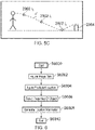
- Figure 5C illustrates location information of an object in accordance with embodiments of the disclosure. That is, Figure 5C illustrates the same example situation as described with reference to Figure 5B of the present disclosure.
- the generating unit 3008 has used the predicted location information P and the one or more properties of the ball detected from the image data which has been acquired in order to generate the location information of the ball P'.
- the location information of the ball P' provides information on the path of the ball through the scene at any instance of time since the ball has been bowled by the player (i.e. provides a continuous representation of the object in the three dimensional environment).
- this location information P' may, in some examples, have been generated by adjusting the predicted location information of the object such that it more closely matches the one or more properties of the object which have been detected. Therefore, the location information P' more closely correlates with the predicted location information P illustrated in Figure 5B .
- the location of an object within a scene can be efficiently and reliably determined from images obtained from a single image capture device (such as image capture device 2006).
- the location information of the object in the scene which is generated by the generating unit 3008 is a three dimensional path or curve trajectory which represents the location of the object in the scene over time.
- this path (or curve trajectory) is acquired by constraining a default path of the object (the predicted location) based on the one or properties of the object which have been determined from the image data acquired by the acquiring unit 3004.
- this location information can then be used in order to determine additional information regarding the object.
- the location information of the object may be used in order to define a three dimensional search ellipse representing where the ball is likely to be located at a particular future time, depending on what information has already been given.
- the location information can be extrapolated in order to determine the likely location of the ball at a future instance of time.
- the size of the search ellipse may be based on the uncertainty in the model and may shrink as further image data is acquired from the image capture device.
- the location information of the object may be used in order to determine the time and location at which the ball hit the ground (i.e. bounced) even if the time of bounce was not captured in the image data itself (owing to the discrete nature of the images).
- the confidence (level of uncertainty) in the bounce time will depend, at least in part, on the amount of pre-bounce image data which is acquired by the image capture device.
- the range of bounce times can be constrained by determining that the actual ball speed is within a certain percentage range of the default ball speed (e.g. within a range of 5% of the default ball speed for the player).
- the post-bounce data may be used in order to more accurately determine the bounce time and position. That is, the pre-bounce image data can be supplemented with post-bounce image data in order to more accurately constrain the pre-bounce trajectory through further refinement of the coefficients of the default trajectory.
- the detecting unit 3006 may have detected the height of the ball at the time it passes the target 2004 (relative to the known height of the target) as one or more properties of the object.
- the generating unit 3008 may use this information in order to further constrain the location information of the object.
- the post bounce information should have no spin in any direction on the drag curve, only gravity and wind resistance should be acting on the ball at this stage.
- the location information which has been generated by the generating unit 3008 may also be used in order to obtain further information such as the spin of the ball, for example. That is, once the location information of the object through the scene has been generated by the generating unit, the parameters of the default trajectory of the object have been constrained. As such, these parameters can then be used in order to determine certain further information (such as the spin of the ball) depending on the path of the object through the scene. For example, if the path of the object through the scene shows that the ball swerves sideways along its path, then it can be determined that the ball spins about its vertical axis. Moreover, if the path of the object through the scene shows that the ball changes direction at the bounce (at the point of contact with the ground) a level of spin imparted to the ball (e.g. in revolutions per minute) can again be determined.
- further information such as the spin of the ball
- the location information of the object may be particularly useful for a person (such as a coach or the like) who wishes to use the additional information in order to assist in training the player such that they can improve their performance in the sport.
- this additional information may be particularly useful for an adjudicator, referee or umpire who is tasked with determining whether or not a player who plays the sport (such as cricket) follows certain rules and restrictions of the game. For example, it may be necessary to determine whether or not the ball would have reached the target if it had not been illegitimately impeded by an object other than the bat of the second player.
- the generating unit 3008 of the apparatus 3000 generates location information of the object.
- the location of an object within a scene can be efficiently and reliably determined from images obtained from a single image capture device.
- the hardware requirements to generate location information of an object within a scene are substantially reduced.
- the location of the object in the images of the scene can be further analysed in order to determine further additional information regarding the object.
- the additional information (including the location of the object) which can be determined by embodiments of the disclosure may be particularly advantageous when used for training in order to improve the performance of a physical skill or performance of a physical task.
- the detecting unit 3006 of apparatus 3000 is configured to detect one or more properties of the object indicative of the observed location of the object in the scene from the image data which has been acquired.
- the detecting unit 3006 may also be configured to use one or more additional sources of information in order to determine the one or more properties of the object. That is, the detecting unit may be configured to detect said properties of the object using information additional to the image data which has been acquired from the image capture device.
- the image capture device 2006 may also provide an audio recording from the scene. This audio recording can then also be used by the detecting unit 3006 in order to detect the one or more properties of the object.
- the detecting unit may use information related to the speed of the object in order to further restrict the location of the object in the scene. That is, if audio from the scene is also available, then the audio may be used by the detecting unit when detecting the location of the object.
- the detecting unit may use information related to the speed of the object in order to further restrict the location of the object in the scene. That is, if audio from the scene is also available, then the audio may be used by the detecting unit when detecting the location of the object.
- the ball will make a noise when it bounces on the ground.
- the sound of the ball bouncing on the floor can then be detected in the audio recording in order to identify the time at which the ball makes contact with the floor. This can then be used as a further constraint of the location of the object within the three dimensional environment.
- the detecting unit 3006 may be configured to use further information such as the speed of the ball as detected by an external device (such as a radar gun) when detecting the one or more properties of the object in accordance with the present disclosure.
- This further information (such as the speed of the ball) may be received by apparatus 3000 directly from the external device.
- this further information may be provided to apparatus 3000 by a user (such as coach 2006) using a user input device such as user input 1006 as described with reference to Figure 1 of the present disclosure.
- certain information may be provided to apparatus 3000 describing the location from which the ball is bowled (e.g. as input by a user such as coach 2008, for example). This information may also be used by detecting unit 3006 as an additional source of information when detecting the one or more properties of the object.
- the detecting unit 3006 may further be configured to use certain additional sources of information (such as a sound or audio recording) when detecting the one or more properties of the object. This can further improve the accuracy and reliability of the information regarding the observed location of the ball in the scene which is determined.
- additional sources of information such as a sound or audio recording
- Figure 6 illustrates an example method of the present disclosure.
- step S6002 the method comprises acquiring image data of a scene from an image capture device. Once the image data has been acquired, the method then proceeds to step S6004.
- step S6004 the method comprises acquiring predicted location information of an object in the scene indicative of a region of the scene in which the object is predicted to be located at a given time. Then, the method proceeds to step S6006.
- step S6006 the method comprises detecting one or more properties of the object from the image data, the properties of the object indicative of an observed location of the object in the scene. Once the one or more properties of the object have been detected form the image data, the method proceeds to step S6008.
- step S6008 the method comprises generating location information of the object in the scene using the predicted location information and the one of more properties of the object.
- step S6010 The method then proceeds to and ends with step S6010.
- steps of the method have been described in sequence the present disclosure is not particularly limited in this regard. That is, the steps of the method of the present disclosure may be performed in an order different to the order which is illustrated in Figure 6 of the present disclosure. For example, a number of the steps of the method (such as steps S6002 and S6004) may be performed in a different sequence to that illustrated in Figure 6 . In fact, a number of the steps of the method of the present disclosure may also be performed in parallel.
- the embodiments of the disclosure have, in part, been described with reference to an example situation such as that illustrated in Figure 2 of the present disclosure, it will be appreciated that the present disclosure is not particularly limited in this respect.
- the embodiments of the disclosure can be used in order to determine location information for an object other than a ball in a sporting event.
- the embodiments of the disclosure may be applied to any type of event where it is desired that location information of an object is determined from images captured by a simple image capture system (such as a single image capture device).
- a simple image capture system such as a single image capture device
- the embodiments of the present disclosure can be applied more generally to any sport where it is desired that the location of an object is determined (e.g. football, snooker, golf or the like).
- Described embodiments may be implemented in any suitable form including hardware, software, firmware or any combination of these. Described embodiments may optionally be implemented at least partly as computer software running on one or more data processors and/or digital signal processors.
- the elements and components of any embodiment may be physically, functionally and logically implemented in any suitable way. Indeed the functionality may be implemented in a single unit, in a plurality of units or as part of other functional units. As such, the disclosed embodiments may be implemented in a single unit or may be physically and functionally distributed between different units, circuitry and/or processors.
Landscapes
- Engineering & Computer Science (AREA)
- Physics & Mathematics (AREA)
- General Physics & Mathematics (AREA)
- Theoretical Computer Science (AREA)
- Computer Vision & Pattern Recognition (AREA)
- Multimedia (AREA)
- Life Sciences & Earth Sciences (AREA)
- Bioinformatics & Cheminformatics (AREA)
- Bioinformatics & Computational Biology (AREA)
- Evolutionary Biology (AREA)
- Probability & Statistics with Applications (AREA)
- Image Analysis (AREA)
Applications Claiming Priority (1)
| Application Number | Priority Date | Filing Date | Title |
|---|---|---|---|
| GB2106722.8A GB2606539A (en) | 2021-05-12 | 2021-05-12 | Apparatus, method and computer program product for generating location information of an object in a scene |
Publications (1)
| Publication Number | Publication Date |
|---|---|
| EP4089636A1 true EP4089636A1 (de) | 2022-11-16 |
Family
ID=76523216
Family Applications (1)
| Application Number | Title | Priority Date | Filing Date |
|---|---|---|---|
| EP22171505.5A Pending EP4089636A1 (de) | 2021-05-12 | 2022-05-04 | Vorrichtung, verfahren und computerprogrammprodukt zur erzeugung von ortsinformationen eines objekts in einer szene |
Country Status (3)
| Country | Link |
|---|---|
| US (1) | US20220366573A1 (de) |
| EP (1) | EP4089636A1 (de) |
| GB (1) | GB2606539A (de) |
Citations (3)
| Publication number | Priority date | Publication date | Assignee | Title |
|---|---|---|---|---|
| GB2403362A (en) * | 2003-06-27 | 2004-12-29 | Roke Manor Research | Calculating the location of an impact event using acoustic and video based data |
| WO2007035878A2 (en) * | 2005-09-20 | 2007-03-29 | Jagrut Patel | Method and apparatus for determining ball trajectory |
| EP2694166A2 (de) * | 2011-04-05 | 2014-02-12 | Nike International Ltd. | Systeme und verfahren zum speichern und analysieren von golfdaten, einschliesslich gemeinsamer und individueller golfdatensammlung und speicherung an einem zentralen hub |
Family Cites Families (4)
| Publication number | Priority date | Publication date | Assignee | Title |
|---|---|---|---|---|
| GB9929193D0 (en) * | 1999-12-10 | 2000-02-02 | Roke Manor Research | Video processing apparatus |
| US20160212385A1 (en) * | 2015-01-21 | 2016-07-21 | Sportstech LLC | Real-Time Sports Advisory System Using Ball Trajectory Prediction |
| US20210125349A1 (en) * | 2019-10-25 | 2021-04-29 | Ji Eul Song | Systems and methods for visualizing ball trajectory in real-time |
| GB2596080A (en) * | 2020-06-16 | 2021-12-22 | Sony Europe Bv | Apparatus, method and computer program product for predicting whether an object moving across a surface will reach a target destination |
-
2021
- 2021-05-12 GB GB2106722.8A patent/GB2606539A/en not_active Withdrawn
-
2022
- 2022-04-25 US US17/728,770 patent/US20220366573A1/en active Pending
- 2022-05-04 EP EP22171505.5A patent/EP4089636A1/de active Pending
Patent Citations (3)
| Publication number | Priority date | Publication date | Assignee | Title |
|---|---|---|---|---|
| GB2403362A (en) * | 2003-06-27 | 2004-12-29 | Roke Manor Research | Calculating the location of an impact event using acoustic and video based data |
| WO2007035878A2 (en) * | 2005-09-20 | 2007-03-29 | Jagrut Patel | Method and apparatus for determining ball trajectory |
| EP2694166A2 (de) * | 2011-04-05 | 2014-02-12 | Nike International Ltd. | Systeme und verfahren zum speichern und analysieren von golfdaten, einschliesslich gemeinsamer und individueller golfdatensammlung und speicherung an einem zentralen hub |
Non-Patent Citations (1)
| Title |
|---|
| KELLEY J ET AL: "Validation of a live, automatic ball velocity and spin rate finder in tennis", PROCEDIA ENGINEERING, ELSEVIER BV, NL, vol. 2, no. 2, 1 June 2010 (2010-06-01), pages 2967 - 2972, XP027184636, ISSN: 1877-7058, [retrieved on 20100601] * |
Also Published As
| Publication number | Publication date |
|---|---|
| US20220366573A1 (en) | 2022-11-17 |
| GB2606539A (en) | 2022-11-16 |
Similar Documents
| Publication | Publication Date | Title |
|---|---|---|
| US12423834B1 (en) | Systems and methods for monitoring user performance in launching an object at a sporting event | |
| US12036465B2 (en) | System and method for player's identification | |
| US11049258B2 (en) | Stereoscopic image capture with performance outcome prediction in sporting environments | |
| US8189857B2 (en) | Methods and processes for detecting a mark on a playing surface and for tracking an object | |
| Pingali et al. | Visualization of sports using motion trajectories: providing insights into performance, style, and strategy | |
| EP2850823A1 (de) | System und verfahren zum automatischen filmen und wiedergeben von sportveranstaltungen | |
| US10786742B1 (en) | Broadcast synchronized interactive system | |
| US7868914B2 (en) | Video event statistic tracking system | |
| US11893808B2 (en) | Learning-based 3D property extraction | |
| US11103763B2 (en) | Basketball shooting game using smart glasses | |
| CN113343844A (zh) | 球类比赛判罚指令自动生成方法、系统和服务器 | |
| US11615580B2 (en) | Method, apparatus and computer program product for generating a path of an object through a virtual environment | |
| EP4089636A1 (de) | Vorrichtung, verfahren und computerprogrammprodukt zur erzeugung von ortsinformationen eines objekts in einer szene | |
| EP3836012B1 (de) | Vorrichtung, computerprogramm und verfahren zur bestimmung des von einem spieler durchgeführten handballs | |
| GB2567800A (en) | Detecting ball strike position | |
| KR102725391B1 (ko) | 골프 코스 리스트 제공 장치 및 골프 코스 리스트 제공 방법 | |
| KR101959010B1 (ko) | 비디오 스코어보드 서비스 장치 | |
| KR101983739B1 (ko) | 비디오 스코어보드 서비스 장치 | |
| US12518794B1 (en) | Video editing system and video editing method | |
| CN118803302A (zh) | 数据展示方法、装置、电子设备、存储介质和程序产品 | |
| JPH08511392A (ja) | 映像内における広告の検出、識別および編入のための装置および方法 |
Legal Events
| Date | Code | Title | Description |
|---|---|---|---|
| PUAI | Public reference made under article 153(3) epc to a published international application that has entered the european phase |
Free format text: ORIGINAL CODE: 0009012 |
|
| STAA | Information on the status of an ep patent application or granted ep patent |
Free format text: STATUS: REQUEST FOR EXAMINATION WAS MADE |
|
| 17P | Request for examination filed |
Effective date: 20220521 |
|
| AK | Designated contracting states |
Kind code of ref document: A1 Designated state(s): AL AT BE BG CH CY CZ DE DK EE ES FI FR GB GR HR HU IE IS IT LI LT LU LV MC MK MT NL NO PL PT RO RS SE SI SK SM TR |
|
| STAA | Information on the status of an ep patent application or granted ep patent |
Free format text: STATUS: EXAMINATION IS IN PROGRESS |
|
| 17Q | First examination report despatched |
Effective date: 20241010 |