EP4089655B1 - Interface acoustique pour un dispositif d'alarme - Google Patents
Interface acoustique pour un dispositif d'alarme Download PDFInfo
- Publication number
- EP4089655B1 EP4089655B1 EP22169570.3A EP22169570A EP4089655B1 EP 4089655 B1 EP4089655 B1 EP 4089655B1 EP 22169570 A EP22169570 A EP 22169570A EP 4089655 B1 EP4089655 B1 EP 4089655B1
- Authority
- EP
- European Patent Office
- Prior art keywords
- frequency
- processor
- control signals
- acoustic interface
- acoustic
- Prior art date
- Legal status (The legal status is an assumption and is not a legal conclusion. Google has not performed a legal analysis and makes no representation as to the accuracy of the status listed.)
- Active
Links
Images


Classifications
-
- G—PHYSICS
- G10—MUSICAL INSTRUMENTS; ACOUSTICS
- G10K—SOUND-PRODUCING DEVICES; METHODS OR DEVICES FOR PROTECTING AGAINST, OR FOR DAMPING, NOISE OR OTHER ACOUSTIC WAVES IN GENERAL; ACOUSTICS NOT OTHERWISE PROVIDED FOR
- G10K9/00—Devices in which sound is produced by vibrating a diaphragm or analogous element, e.g. fog horns, vehicle hooters or buzzers
- G10K9/12—Devices in which sound is produced by vibrating a diaphragm or analogous element, e.g. fog horns, vehicle hooters or buzzers electrically operated
- G10K9/122—Devices in which sound is produced by vibrating a diaphragm or analogous element, e.g. fog horns, vehicle hooters or buzzers electrically operated using piezoelectric driving means
-
- G—PHYSICS
- G08—SIGNALLING
- G08B—SIGNALLING SYSTEMS, e.g. PERSONAL CALLING SYSTEMS; ORDER TELEGRAPHS; ALARM SYSTEMS
- G08B3/00—Audible signalling systems, e.g. audible personal calling systems
- G08B3/10—Audible signalling systems, e.g. audible personal calling systems using electric transmission; using electromagnetic transmission
-
- G—PHYSICS
- G10—MUSICAL INSTRUMENTS; ACOUSTICS
- G10K—SOUND-PRODUCING DEVICES; METHODS OR DEVICES FOR PROTECTING AGAINST, OR FOR DAMPING, NOISE OR OTHER ACOUSTIC WAVES IN GENERAL; ACOUSTICS NOT OTHERWISE PROVIDED FOR
- G10K9/00—Devices in which sound is produced by vibrating a diaphragm or analogous element, e.g. fog horns, vehicle hooters or buzzers
- G10K9/18—Details, e.g. bulbs, pumps, pistons, switches or casings
-
- B—PERFORMING OPERATIONS; TRANSPORTING
- B06—GENERATING OR TRANSMITTING MECHANICAL VIBRATIONS IN GENERAL
- B06B—METHODS OR APPARATUS FOR GENERATING OR TRANSMITTING MECHANICAL VIBRATIONS OF INFRASONIC, SONIC, OR ULTRASONIC FREQUENCY, e.g. FOR PERFORMING MECHANICAL WORK IN GENERAL
- B06B1/00—Methods or apparatus for generating mechanical vibrations of infrasonic, sonic, or ultrasonic frequency
- B06B1/02—Methods or apparatus for generating mechanical vibrations of infrasonic, sonic, or ultrasonic frequency making use of electrical energy
- B06B1/0207—Driving circuits
- B06B1/0215—Driving circuits for generating pulses, e.g. bursts of oscillations, envelopes
Definitions
- an acoustic interface 1 suitable for an alarm device or any other device for which acoustic encoded information is required to be outputted is shown in block diagram form in Fig. 1(a) and in Fig. 1(b) with a plan view of a piezoelectric disc sounder 2.
- the acoustic signals are generated by a vibratory element, in this case a piezoelectric disc 2 having a main element 3 and a feedback element 4.
- the feedback element 4 is linked to the transistor 5, which drives an oscillator circuit 6 according to a control signal 7 from an encoding processor 8.
- the encoding processor 8 is in one example that of a smoke alarm device, and it is programmed to drive the interface 1 to provide data concerning the alarm device.
- the microcontroller MCU 8 is programmed to provide a higher data rate and a lower audio level than is known.
- the acoustic interface 1 is part of a smoke alarm device in this example, the microcontroller being part of the alarm device, and is preferably the main controller. However, the interface may be part of a different device such as a domestic appliance.
- the microcontroller 8 is programmed to generate a test output record including various items of data such as the device's serial number, the battery level, a contamination level if it is an optical alarm, an event log, and an installation date. This information is encoded by control of the high voltage oscillator linked to the piezoelectric disc horn, which is an item required by the alarm device anyway for generating an audible alarm output.
- the data which is conveyed may include any one or more of: preamble bits, a device identification number, a device status flag, battery status, contamination status, alarm events, faulty smoke sensor, installation date, location, whether the device is in standby, hush, or alarm modes.
- Having a unique serial number greatly helps with the tracking of smoke alarm devices - the devices can be sent back to the manufacturer for analysis and the subsequent report will clearly identify the unit and allow the maintenance company to relate it to the apartment from which it was removed. For example, if the unit was heavily contaminated or damaged, and it was clear that this was caused by a tenant, then the tenant (or landlord) could be billed for the replacement costs of fitting a new unit.
- Frequency Shift-Keying encodes data in the frequency of the control signal.
- a minimum of two controllable frequencies is required. One frequency is used to represent the binary '0's, while the other is used for ⁇ 1's.
- This is more efficient than single frequency encoding, which relies on time delays or transitions to determine whether the bit is a '1' or '0'.
- Manchester encoding for example is only 50% efficient because its data rate is only half the clock rate since it must generate transitions from low-to-high or high-to-low, in order to be decoded successfully.
- FSK does not have this issue and can be much faster. Many modern wireless systems, such as Wi-Fi TM , use some version of FSK.
- the control pulses are significantly shorter than the period of the disc's natural frequency, in order to prevent (or reduce) resonance at the fundamental.
- the processor 8 is programmed to provide the control signals 7 so that the control signal frequency f d does not approach f N , or so that the control signal pulse width t p does not approach 1/f N .
- the fundamental frequency will not dominate the response and other useful frequencies are produced.
- f d is greater than f N by a value in the range of 40% to 250%.
- the control signal pulse width t p is much less than the disc's natural frequency period 1/f N , and in general it is preferred that it is less than 8% of 1/f N .
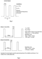
- control signals used for generating binary '0's are at 6.8kHz and binary '1's are at 5.5kHz, from the 3kHz natural frequency piezo disc 2, as shown in Fig. 3 .
- the pulse width is 16 ⁇ s and the gap is 165 ⁇ s giving a repetition rate of 181 ⁇ s.
- the pulse width of 16 ⁇ s is much less than the 1/f N duration of 333 ⁇ s.
- the repetition rate is 147 ⁇ s and the pulse width is the same (16 ⁇ s).
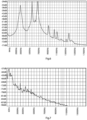
- the processor 8 control signal 7 drive scheme avoids a situation such as shown in Fig. 4 in which a high dB level is reached at the disc's fundamental. Referring to Fig. 4 , when the control signal pulse widths are greater than 1/f N the output audio signal is dominated by a high amplitude 3kHz signal, and its 3 rd harmonic.
- the output audio signal shows a dominant peak at a disc vibration (sound) frequency of 6.8kHz, which is approximately 5dB larger than the disc's natural vibration frequency of 3kHz.
- the fundamental intensity has decreased by over 30dB, and is thus significantly quieter while also generating a more controllable frequency.
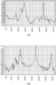
- Fig. 6 demonstrates the audio output for a binary-FSK signal generated by the above procedure.
- data was transmitted by alternately driving at frequencies of 5.5kHz and 6.8kHz, representing binary 1s and 0s respectively.
- the decoder listens for audio signals at 5.5kHz and 6.8kHz to recognize 1s and 0s.
- the difference between a binary 1 or 0 must be as clear as possible.
- the chosen FSK output frequencies can be produced independently with little cross-talk. For example, when a 6.8kHz output is generated, the output at 5.5kHz should be as low as possible. Therefore, an important parameter for decoding performance is the relative ON-OFF amplitude difference between the chosen FSK frequencies.
- the acoustic interface uses Binary FSK modulation, one frequency for binary 1, and another frequency for the 0. Turning it on and off rapidly at frequencies greater than the disc's natural frequency by at least 40% has the effect of dampening the feedback of the primary resonance (in one example, 3kHz), preventing the disc from resonating at the natural frequency. It is repeatedly interrupted and is used to generate other frequencies of sufficient amplitude that they become useful. Because it is not driven at resonance, disc vibration dampens down a lot faster, so higher data rate is possible.
- the microcontroller can generate and control multiple control signal frequencies. When it generates say 6.8kHz for binary 0, that 6.8kHz is not unintentionally generated for a binary 1 at 5.5kHz.
- the acoustic interface is at least 5 times faster and significantly quieter than if the drive signals have a frequency close to the disc's natural frequency.
- the control is via the duty cycle and frequency of the pulses used to turn on/off the piezo.
- the drive processor providing the control signals is a dedicated IC of the host device, while in other examples it is an LC oscillator circuit. In general, it is preferred that there be a 3-wire arrangement with feedback from the vibrating element such as a piezo.
- the characteristics of the smartphone microphone system are important to the overall operation of the data transfer.
- Most modern phones have active noise-cancellation algorithms and use multiple microphones to reduce noise.
- the data transmission can be regarded as noise by the phone, and it therefore actively attempts to eliminate this perceived "noise" signal. This can severely interfere with decoding the data and leads to errors.
- An additional problem is that different makes and models of phones behave differently in terms of noise cancelling and therefore there is no single range of preferred frequencies that will work for audio data transmission on all phones. Having the ability to decode with different frequencies when required is an advantage.
- the processor is configured to utilise the harmonics which are naturally produced by the disc when driven. For example, as shown in Fig. 8 , when driven at 5.5kHz, a harmonic at 11kHz is created.
- Fig. 9 shows the sound output when driven at 4.5kHz, with disc vibration (sound) intensity peaks at 5.5kHz and 9kHz. It also shows a relatively strong 3 rd harmonic at 13.5kHz. As can be seen, the 9kHz output signal is actually larger than the signal at the driven frequency of 4.5kHz. This is because 9kHz is a multiple of the disc's natural frequency. The disc will therefore be relatively efficient at oscillating at 9kHz even though it is electronically driven at 4.5kHz.
- the data transmitted is thus present in the 4.5kHz signal and the 9kHz signal and the 13.5 kHz signal.
- This provides three sources from which decoding can take place to recover the data. This is very beneficial in the context of noise-cancelling smart-phone systems, where one range of frequencies may be more prone to cancellation on a particular phone.
- Successful decoding of the transmitted data is more likely when decoding on more than a single frequency. For example, if a particular phone has a weak response at 4.5kHz, the decoded signal may have errors, but decoding at 9kHz or 13.5kHz can resolve the errors.
- acoustic interface has been described as being for a smoke alarm device, it may be for any other appliance for which status information is to be communicated acoustically to be picked up and decoded by a processor such as a smartphone.
- Fig. 9 shows the sound output when driven at 4.5kHz, with disc vibration (sound) intensity peaks at 5.5kHz and 9kHz. It also shows a relatively strong 3 rd harmonic at 13.5kHz. As can be seen, the 9kHz output signal is actually larger than the signal at the driven frequency of 4.5kHz. This is because 9kHz is a multiple of the disc's natural frequency. The disc will therefore be relatively efficient at oscillating at 9kHz even though it is electronically driven at 4.5kHz.
Landscapes
- Physics & Mathematics (AREA)
- Engineering & Computer Science (AREA)
- Acoustics & Sound (AREA)
- Multimedia (AREA)
- Electromagnetism (AREA)
- General Physics & Mathematics (AREA)
- Piezo-Electric Transducers For Audible Bands (AREA)
Claims (15)
- Interface acoustique (1) pour un dispositif tel qu'un dispositif d'alarme, l'interface acoustique comprenant un élément vibratoire (2) et un circuit d'excitation (8, 5) avec un processeur (8) pour délivrer des signaux de commande électriques d'excitation (7) à l'élément pour le faire vibrer et générer un signal sonore avec des données binaires codées, l'élément vibrant (2) ayant une fréquence propre,
l'interface acoustique étant caractérisée en ce que :
les signaux de commande sont codés en fréquence avec des impulsions dont les largeurs d'impulsion (tp) sont inférieures à la période de fréquence propre (1/fN) de l'élément vibrant et dont la fréquence est supérieure à ladite fréquence propre. - Interface acoustique selon la revendication 1, dans laquelle le processeur (8) est configuré pour fournir les signaux de commande par l'intermédiaire d'un transistor de réaction (5) et d'un oscillateur à tension (6).
- Interface acoustique selon la revendication 2, dans laquelle l'élément vibratoire (2) comprend au moins trois contacts électriques dont deux pour l'alimentation et un troisième pour la réaction vers le transistor de réaction (5), l'oscillation mécanique de l'élément vibratoire générant un signal électrique de réaction utilisé pour amplifier ce signal de commande (7).
- Interface acoustique selon l'une quelconque des revendications précédentes, dans laquelle le processeur (8) est configuré pour générer les signaux de commande selon un schéma de modulation par déplacement de fréquence.
- Interface acoustique selon la revendication 4, dans laquelle le processeur est configuré pour générer les signaux de commande selon un schéma de modulation par déplacement de fréquence binaire, où une fréquence est utilisée pour représenter un « 0 » binaire et une fréquence différente est utilisée pour représenter un « 1 ».
- Interface acoustique selon la revendication 5, dans laquelle le processeur est configuré pour générer les signaux de commande avec une différence de fréquence entre les représentations binaires 0 et 1 d'au moins 1 kHz.
- Interface acoustique selon l'une quelconque des revendications précédentes, dans laquelle le processeur est configuré pour générer les signaux de commande avec une largeur d'impulsion tp inférieure à 8 % de ladite période de fréquence propre.
- Interface acoustique selon l'une quelconque des revendications précédentes, dans laquelle le processeur est configuré pour générer les signaux de commande avec une fréquence supérieure d'au moins 40 % à ladite fréquence propre.
- Interface acoustique selon l'une quelconque des revendications précédentes, dans laquelle le processeur est configuré pour générer les signaux de commande avec une fréquence qui provoque au moins un harmonique supplémentaire de l'élément vibratoire, l'harmonique supplémentaire étant le double ou le triple de la fréquence du signal de commande d'excitation et étant utilisé pour coder une valeur binaire audit au moins un harmonique supplémentaire.
- Dispositif d'alarme comprenant un capteur d'état, un contrôleur, un émetteur sonore d'alarme avec un élément vibrant et une interface acoustique selon l'une quelconque des revendications précédentes, le contrôleur étant configuré pour coder des données de statut d'alarme dans la sortie acoustique de l'interface.
- Dispositif d'alarme selon la revendication 10, dans lequel l'élément vibrant de l'interface acoustique est également l'émetteur sonore d'alarme.
- Dispositif d'alarme selon l'une des revendications 10 ou 11, le dispositif d'alarme étant un dispositif d'alarme incendie et le capteur d'état étant un détecteur de chaleur ou de fumée.
- Système comprenant une interface acoustique selon l'une quelconque des revendications 1 à 9 ou un dispositif d'alarme selon l'une quelconque des revendications 10 à 12, ainsi qu'un dispositif de décodage comportant un capteur acoustique et un processeur de décodage configuré pour décoder des signaux acoustiques et fournir une sortie de données d'utilisateur.
- Système selon la revendication 13, dans lequel le processeur (8) pour la délivrance de signaux de commande électriques d'excitation (7) est configuré pour fournir les signaux de commande afin de générer un deuxième harmonique, et le processeur de décodage est configuré pour décoder à une fréquence double ou triple de la fréquence de commande d'excitation.
- Système selon la revendication 14, dans lequel ledit décodage par le processeur de décodage est utilisé pour le décodage d'un 0 binaire seulement ou d'un 1 binaire seulement.
Applications Claiming Priority (1)
| Application Number | Priority Date | Filing Date | Title |
|---|---|---|---|
| EP21173146 | 2021-05-10 |
Publications (3)
| Publication Number | Publication Date |
|---|---|
| EP4089655A1 EP4089655A1 (fr) | 2022-11-16 |
| EP4089655B1 true EP4089655B1 (fr) | 2024-07-10 |
| EP4089655C0 EP4089655C0 (fr) | 2024-07-10 |
Family
ID=75887973
Family Applications (1)
| Application Number | Title | Priority Date | Filing Date |
|---|---|---|---|
| EP22169570.3A Active EP4089655B1 (fr) | 2021-05-10 | 2022-04-22 | Interface acoustique pour un dispositif d'alarme |
Country Status (1)
| Country | Link |
|---|---|
| EP (1) | EP4089655B1 (fr) |
Family Cites Families (4)
| Publication number | Priority date | Publication date | Assignee | Title |
|---|---|---|---|---|
| DE202011110746U1 (de) | 2010-12-06 | 2016-01-26 | E.I. Technology Shannon Industrial Estate | Alarmsystem unter Verwendung von zeitlich codierten akustischen Nachrichten |
| US20130197320A1 (en) * | 2012-01-26 | 2013-08-01 | David E. Albert | Ultrasonic digital communication of biological parameters |
| US9608848B2 (en) * | 2014-10-22 | 2017-03-28 | The Board Of Trustees Of The University Of Illinois | Communicating through physical vibration |
| EP3502741B1 (fr) * | 2017-12-21 | 2022-04-06 | Aisin Corporation | Capteur de détection d'obstacles |
-
2022
- 2022-04-22 EP EP22169570.3A patent/EP4089655B1/fr active Active
Also Published As
| Publication number | Publication date |
|---|---|
| EP4089655A1 (fr) | 2022-11-16 |
| EP4089655C0 (fr) | 2024-07-10 |
Similar Documents
| Publication | Publication Date | Title |
|---|---|---|
| RU2484522C2 (ru) | Система для бытовых электроприборов и способ ее функционирования | |
| US20210044906A1 (en) | Methods and apparatuses for driving audio and ultrasonic signals from the same transducer | |
| JP2005537738A (ja) | Do−not−disturbモードをオーバーライドする装置及び方法 | |
| CN112703681A (zh) | 从用户终端到另一装置的数据传输 | |
| CN106851516A (zh) | 电子装置及基于响度的检测方法 | |
| CN106878910A (zh) | 出声控制方法和电子装置 | |
| MXPA04012060A (es) | Dispositivo de emision de senal acustica para vehiculos. | |
| JP2002119912A (ja) | 複合音響アクチュエータ駆動回路及び携帯情報端末 | |
| EP4089655B1 (fr) | Interface acoustique pour un dispositif d'alarme | |
| EP1509337B1 (fr) | Circuit de commande electronique et dispositif emetteur de signaux acoustiques pour vehicules | |
| RU2004139117A (ru) | Система связи | |
| US7501935B2 (en) | Multi-frequency fire alarm sounder | |
| FR2757301A1 (fr) | Dispositif d'avertissement de la presence d'un signal | |
| JP2025509480A (ja) | アラーム及びその他の音のための補聴器 | |
| US3932711A (en) | Transmission of voice or sound through telegraphy | |
| TWI505181B (zh) | 音樂播放系統 | |
| CN108432159A (zh) | 信息提供装置以及信息提供系统 | |
| US20160380814A1 (en) | Systems and methods for provisioning a battery-powered device to access a wireless communications network | |
| JP2008016290A (ja) | 照明制御用リモコンシステムおよびリモコン装置 | |
| JPH033538A (ja) | 電話装置 | |
| CN103051779A (zh) | 一种手机来电/来信提示方法及其装置 | |
| WO2019191074A1 (fr) | Compensation de température pour sondeur piézoélectrique | |
| US20250060480A1 (en) | Improved presence detection | |
| KR200336946Y1 (ko) | 적외선 발광 다이오드를 이용한 레이저 도청방지장치 | |
| JPH01103064A (ja) | テレコントロール受信装置 |
Legal Events
| Date | Code | Title | Description |
|---|---|---|---|
| PUAI | Public reference made under article 153(3) epc to a published international application that has entered the european phase |
Free format text: ORIGINAL CODE: 0009012 |
|
| STAA | Information on the status of an ep patent application or granted ep patent |
Free format text: STATUS: THE APPLICATION HAS BEEN PUBLISHED |
|
| AK | Designated contracting states |
Kind code of ref document: A1 Designated state(s): AL AT BE BG CH CY CZ DE DK EE ES FI FR GB GR HR HU IE IS IT LI LT LU LV MC MK MT NL NO PL PT RO RS SE SI SK SM TR |
|
| STAA | Information on the status of an ep patent application or granted ep patent |
Free format text: STATUS: REQUEST FOR EXAMINATION WAS MADE |
|
| 17P | Request for examination filed |
Effective date: 20230505 |
|
| RBV | Designated contracting states (corrected) |
Designated state(s): AL AT BE BG CH CY CZ DE DK EE ES FI FR GB GR HR HU IE IS IT LI LT LU LV MC MK MT NL NO PL PT RO RS SE SI SK SM TR |
|
| REG | Reference to a national code |
Ref country code: DE Ref legal event code: R079 Free format text: PREVIOUS MAIN CLASS: G08B0003100000 Ipc: G10K0009122000 Ref country code: DE Ref legal event code: R079 Ref document number: 602022004410 Country of ref document: DE Free format text: PREVIOUS MAIN CLASS: G08B0003100000 Ipc: G10K0009122000 |
|
| GRAP | Despatch of communication of intention to grant a patent |
Free format text: ORIGINAL CODE: EPIDOSNIGR1 |
|
| STAA | Information on the status of an ep patent application or granted ep patent |
Free format text: STATUS: GRANT OF PATENT IS INTENDED |
|
| INTG | Intention to grant announced |
Effective date: 20240507 |
|
| RIC1 | Information provided on ipc code assigned before grant |
Ipc: B06B 1/02 20060101ALN20240422BHEP Ipc: G08B 3/10 20060101ALI20240422BHEP Ipc: G10K 9/18 20060101ALI20240422BHEP Ipc: G10K 9/122 20060101AFI20240422BHEP |
|
| GRAS | Grant fee paid |
Free format text: ORIGINAL CODE: EPIDOSNIGR3 |
|
| GRAA | (expected) grant |
Free format text: ORIGINAL CODE: 0009210 |
|
| STAA | Information on the status of an ep patent application or granted ep patent |
Free format text: STATUS: THE PATENT HAS BEEN GRANTED |
|
| AK | Designated contracting states |
Kind code of ref document: B1 Designated state(s): AL AT BE BG CH CY CZ DE DK EE ES FI FR GB GR HR HU IE IS IT LI LT LU LV MC MK MT NL NO PL PT RO RS SE SI SK SM TR |
|
| REG | Reference to a national code |
Ref country code: CH Ref legal event code: EP |
|
| REG | Reference to a national code |
Ref country code: DE Ref legal event code: R096 Ref document number: 602022004410 Country of ref document: DE |
|
| U01 | Request for unitary effect filed |
Effective date: 20240711 |
|
| U07 | Unitary effect registered |
Designated state(s): AT BE BG DE DK EE FI FR IT LT LU LV MT NL PT SE SI Effective date: 20240718 |
|
| PG25 | Lapsed in a contracting state [announced via postgrant information from national office to epo] |
Ref country code: NO Free format text: LAPSE BECAUSE OF FAILURE TO SUBMIT A TRANSLATION OF THE DESCRIPTION OR TO PAY THE FEE WITHIN THE PRESCRIBED TIME-LIMIT Effective date: 20241010 |
|
| PG25 | Lapsed in a contracting state [announced via postgrant information from national office to epo] |
Ref country code: GR Free format text: LAPSE BECAUSE OF FAILURE TO SUBMIT A TRANSLATION OF THE DESCRIPTION OR TO PAY THE FEE WITHIN THE PRESCRIBED TIME-LIMIT Effective date: 20241011 Ref country code: PL Free format text: LAPSE BECAUSE OF FAILURE TO SUBMIT A TRANSLATION OF THE DESCRIPTION OR TO PAY THE FEE WITHIN THE PRESCRIBED TIME-LIMIT Effective date: 20240710 |
|
| PG25 | Lapsed in a contracting state [announced via postgrant information from national office to epo] |
Ref country code: IS Free format text: LAPSE BECAUSE OF FAILURE TO SUBMIT A TRANSLATION OF THE DESCRIPTION OR TO PAY THE FEE WITHIN THE PRESCRIBED TIME-LIMIT Effective date: 20241110 |
|
| PG25 | Lapsed in a contracting state [announced via postgrant information from national office to epo] |
Ref country code: HR Free format text: LAPSE BECAUSE OF FAILURE TO SUBMIT A TRANSLATION OF THE DESCRIPTION OR TO PAY THE FEE WITHIN THE PRESCRIBED TIME-LIMIT Effective date: 20240710 |
|
| PG25 | Lapsed in a contracting state [announced via postgrant information from national office to epo] |
Ref country code: RS Free format text: LAPSE BECAUSE OF FAILURE TO SUBMIT A TRANSLATION OF THE DESCRIPTION OR TO PAY THE FEE WITHIN THE PRESCRIBED TIME-LIMIT Effective date: 20241010 Ref country code: ES Free format text: LAPSE BECAUSE OF FAILURE TO SUBMIT A TRANSLATION OF THE DESCRIPTION OR TO PAY THE FEE WITHIN THE PRESCRIBED TIME-LIMIT Effective date: 20240710 |
|
| PG25 | Lapsed in a contracting state [announced via postgrant information from national office to epo] |
Ref country code: RS Free format text: LAPSE BECAUSE OF FAILURE TO SUBMIT A TRANSLATION OF THE DESCRIPTION OR TO PAY THE FEE WITHIN THE PRESCRIBED TIME-LIMIT Effective date: 20241010 Ref country code: PL Free format text: LAPSE BECAUSE OF FAILURE TO SUBMIT A TRANSLATION OF THE DESCRIPTION OR TO PAY THE FEE WITHIN THE PRESCRIBED TIME-LIMIT Effective date: 20240710 Ref country code: NO Free format text: LAPSE BECAUSE OF FAILURE TO SUBMIT A TRANSLATION OF THE DESCRIPTION OR TO PAY THE FEE WITHIN THE PRESCRIBED TIME-LIMIT Effective date: 20241010 Ref country code: IS Free format text: LAPSE BECAUSE OF FAILURE TO SUBMIT A TRANSLATION OF THE DESCRIPTION OR TO PAY THE FEE WITHIN THE PRESCRIBED TIME-LIMIT Effective date: 20241110 Ref country code: HR Free format text: LAPSE BECAUSE OF FAILURE TO SUBMIT A TRANSLATION OF THE DESCRIPTION OR TO PAY THE FEE WITHIN THE PRESCRIBED TIME-LIMIT Effective date: 20240710 Ref country code: GR Free format text: LAPSE BECAUSE OF FAILURE TO SUBMIT A TRANSLATION OF THE DESCRIPTION OR TO PAY THE FEE WITHIN THE PRESCRIBED TIME-LIMIT Effective date: 20241011 Ref country code: ES Free format text: LAPSE BECAUSE OF FAILURE TO SUBMIT A TRANSLATION OF THE DESCRIPTION OR TO PAY THE FEE WITHIN THE PRESCRIBED TIME-LIMIT Effective date: 20240710 |
|
| PG25 | Lapsed in a contracting state [announced via postgrant information from national office to epo] |
Ref country code: SM Free format text: LAPSE BECAUSE OF FAILURE TO SUBMIT A TRANSLATION OF THE DESCRIPTION OR TO PAY THE FEE WITHIN THE PRESCRIBED TIME-LIMIT Effective date: 20240710 |
|
| U20 | Renewal fee for the european patent with unitary effect paid |
Year of fee payment: 4 Effective date: 20250311 |
|
| PG25 | Lapsed in a contracting state [announced via postgrant information from national office to epo] |
Ref country code: CZ Free format text: LAPSE BECAUSE OF FAILURE TO SUBMIT A TRANSLATION OF THE DESCRIPTION OR TO PAY THE FEE WITHIN THE PRESCRIBED TIME-LIMIT Effective date: 20240710 |
|
| PG25 | Lapsed in a contracting state [announced via postgrant information from national office to epo] |
Ref country code: SK Free format text: LAPSE BECAUSE OF FAILURE TO SUBMIT A TRANSLATION OF THE DESCRIPTION OR TO PAY THE FEE WITHIN THE PRESCRIBED TIME-LIMIT Effective date: 20240710 |
|
| PLBE | No opposition filed within time limit |
Free format text: ORIGINAL CODE: 0009261 |
|
| STAA | Information on the status of an ep patent application or granted ep patent |
Free format text: STATUS: NO OPPOSITION FILED WITHIN TIME LIMIT |
|
| 26N | No opposition filed |
Effective date: 20250411 |
|
| REG | Reference to a national code |
Ref country code: CH Ref legal event code: H13 Free format text: ST27 STATUS EVENT CODE: U-0-0-H10-H13 (AS PROVIDED BY THE NATIONAL OFFICE) Effective date: 20251125 |
|
| PG25 | Lapsed in a contracting state [announced via postgrant information from national office to epo] |
Ref country code: MC Free format text: LAPSE BECAUSE OF FAILURE TO SUBMIT A TRANSLATION OF THE DESCRIPTION OR TO PAY THE FEE WITHIN THE PRESCRIBED TIME-LIMIT Effective date: 20240710 |
|
| PG25 | Lapsed in a contracting state [announced via postgrant information from national office to epo] |
Ref country code: CH Free format text: LAPSE BECAUSE OF NON-PAYMENT OF DUE FEES Effective date: 20250430 |
|
| U20 | Renewal fee for the european patent with unitary effect paid |
Year of fee payment: 5 Effective date: 20260212 |
|
| PGFP | Annual fee paid to national office [announced via postgrant information from national office to epo] |
Ref country code: GB Payment date: 20260212 Year of fee payment: 5 |
|
| PGFP | Annual fee paid to national office [announced via postgrant information from national office to epo] |
Ref country code: IE Payment date: 20260212 Year of fee payment: 5 |
|
| PG25 | Lapsed in a contracting state [announced via postgrant information from national office to epo] |
Ref country code: RO Free format text: LAPSE BECAUSE OF FAILURE TO SUBMIT A TRANSLATION OF THE DESCRIPTION OR TO PAY THE FEE WITHIN THE PRESCRIBED TIME-LIMIT Effective date: 20240710 |