EP4089656A1 - Audiovorrichtung - Google Patents
Audiovorrichtung Download PDFInfo
- Publication number
- EP4089656A1 EP4089656A1 EP22175814.7A EP22175814A EP4089656A1 EP 4089656 A1 EP4089656 A1 EP 4089656A1 EP 22175814 A EP22175814 A EP 22175814A EP 4089656 A1 EP4089656 A1 EP 4089656A1
- Authority
- EP
- European Patent Office
- Prior art keywords
- audio device
- slit
- unit
- housing
- wall portion
- Prior art date
- Legal status (The legal status is an assumption and is not a legal conclusion. Google has not performed a legal analysis and makes no representation as to the accuracy of the status listed.)
- Withdrawn
Links
Images


Classifications
-
- G—PHYSICS
- G08—SIGNALLING
- G08B—SIGNALLING SYSTEMS, e.g. PERSONAL CALLING SYSTEMS; ORDER TELEGRAPHS; ALARM SYSTEMS
- G08B7/00—Signalling systems according to two or more of groups G08B3/00 - G08B6/00
- G08B7/06—Signalling systems according to two or more of groups G08B3/00 - G08B6/00 using electric transmission, e.g. involving audible and visible signalling through the use of sound and light sources
-
- G—PHYSICS
- G08—SIGNALLING
- G08B—SIGNALLING SYSTEMS, e.g. PERSONAL CALLING SYSTEMS; ORDER TELEGRAPHS; ALARM SYSTEMS
- G08B17/00—Fire alarms; Alarms responsive to explosion
- G08B17/10—Actuation by presence of smoke or gases, e.g. automatic alarm devices for analysing flowing fluid materials by the use of optical means
- G08B17/11—Actuation by presence of smoke or gases, e.g. automatic alarm devices for analysing flowing fluid materials by the use of optical means using an ionisation chamber for detecting smoke or gas
- G08B17/113—Constructional details
-
- H—ELECTRICITY
- H04—ELECTRIC COMMUNICATION TECHNIQUE
- H04R—LOUDSPEAKERS, MICROPHONES, GRAMOPHONE PICK-UPS OR LIKE ACOUSTIC ELECTROMECHANICAL TRANSDUCERS; ELECTRIC HEARING AIDS; PUBLIC ADDRESS SYSTEMS
- H04R1/00—Details of transducers, loudspeakers or microphones
- H04R1/02—Casings; Cabinets ; Supports therefor; Mountings therein
-
- G—PHYSICS
- G08—SIGNALLING
- G08B—SIGNALLING SYSTEMS, e.g. PERSONAL CALLING SYSTEMS; ORDER TELEGRAPHS; ALARM SYSTEMS
- G08B7/00—Signalling systems according to two or more of groups G08B3/00 - G08B6/00
- G08B7/06—Signalling systems according to two or more of groups G08B3/00 - G08B6/00 using electric transmission, e.g. involving audible and visible signalling through the use of sound and light sources
- G08B7/062—Signalling systems according to two or more of groups G08B3/00 - G08B6/00 using electric transmission, e.g. involving audible and visible signalling through the use of sound and light sources indicating emergency exits
Definitions
- the present disclosure generally relates to an audio device, and more particularly relates to an audio device configured to alert the user to the presence of some external event such as a fire.
- Patent Literature 1 discloses a known residential fire alarm.
- the residential fire alarm includes a smoke detecting unit with a smoke inlet, which is provided at the center of its cover, and detects the outbreak of a fire when the concentration of smoke produced by a fire reaches a predetermined concentration.
- the residential fire alarm further has sound holes on a lower left-hand side of the smoke detecting unit on the cover.
- a loudspeaker is arranged behind the sound holes to emit an alarm sound and a voice warning message.
- the residential fire alarm may be installed on, for example, the wall surface of a resident's room or bedroom in a dwelling house to detect, in the event of the outbreak of a fire, the fire and start sounding a fire warning.
- Patent Literature 1 JP 2010-49604 A
- an object of the present disclosure to provide an audio device configured to contribute to evacuating a person in an even shorter time while reducing the chances of affecting the cosmetic appearance thereof.
- An audio device is to be installed in a structural component.
- the audio device includes a control unit, a first emission unit, a second emission unit, and a housing.
- the control unit determines, in accordance with information provided about a particular event, whether or not the particular event is present.
- the first emission unit emits, when the control unit determines that the particular event be present, a sound to alert a person to the presence of the particular event.
- the second emission unit emits, in accordance with the information, illuminating light that irradiates a surrounding region.
- the housing houses the control unit, the first emission unit, and the second emission unit.
- the housing includes: a base portion to be fixed onto the structural component; and a front wall portion provided in front of the base portion.
- the front wall portion has a slit provided through a front surface thereof and recessed toward the base portion.
- the slit has: a sound hole provided in a first region of an inner surface of the slit to let the sound come out of the housing; and a window hole provided in a second region of the inner surface of the slit to let the illuminating light come out of the housing.
- an audio device 1 is installed in a structural component C1 (i.e., a building component such as a ceiling or a wall).
- the audio device 1 includes a control unit 10, a first emission unit 11, a second emission unit 12, and a housing 4 as shown in FIG. 5 .
- the control unit 10 determines, in accordance with information provided about a particular event, whether or not the particular event is present.
- the "particular event" is supposed to be a fire, for example. Therefore, the audio device 1 may be implemented as, for example, a fire alarm that emits an alarm sound or any other type of sound at the outbreak of the fire.
- the particular event does not have to be a fire but may also be gas leakage, a tsunami, an earthquake, or intrusion of a suspicious person as long as the event requires sounding an alarm.
- the audio device 1 includes a photoelectric sensor (as a detecting unit 2) for detecting smoke as a built-in component thereof.
- a photoelectric sensor as a detecting unit 2 for detecting smoke as a built-in component thereof.
- the detecting unit 2 may also be a fixed temperature sensor for detecting heat.
- the detecting unit 2 may also be provided separately from the audio device 1.
- the control unit 10 of the audio device 1 may be provided with information about the fire by communicating with another audio device (fire alarm) including the detecting unit.
- the audio device 1 may be installed on a surface (such as a ceiling surface or wall surface) of a structural component C1 such as a resident's room, a bedroom, stairs, or a hallway in a dwelling house.
- a structural component C1 such as a resident's room, a bedroom, stairs, or a hallway in a dwelling house.
- the dwelling house may be a single-family dwelling house or a multi-family dwelling house (i.e., what is called a "mansion" in Japan).
- the audio device 1 may also be installed (on the ceiling surface or wall surface) in a non-residential structural component C1, instead of those dwelling houses.
- non-dwelling structural components examples include office buildings, theaters, movie theaters, public halls, amusement facilities, complex facilities, restaurants, department stores, schools, hotels, inns, hospitals, nursing homes for the elderly, kindergartens, libraries, museums, art museums, underground shopping malls, railway stations, and airports.
- the first emission unit 11 emits an alarm sound to alert the user to the presence of the fire.
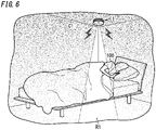
- the second emission unit 12 emits, in accordance with the information about the fire, light that irradiates a surrounding region R1 (see FIG. 6 ).
- the light emitted from the second emission unit 12 will be hereinafter referred to as "illuminating light.” Note that the light emitted from the second emission unit 12 has lower intensity than illuminating light emitted from a general light fixture and may be bright enough to indicate an evacuation route.
- the "surrounding region R1" may be, if the audio device 1 is installed on a ceiling surface, a region that faces the ceiling surface (such a floor surface). On the other hand, if the audio device 1 is installed on a wall surface, the surrounding region R1 may be a region (such as another wall surface) that faces the former wall surface.
- the housing 4 houses the control unit 10, the first emission unit 11, and the second emission unit 12.
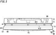
- the housing 4 includes: a base portion 4A (see FIG. 3 ) to be fixed onto a structural component C1; and a front wall portion 4B provided in front of the base portion 4A.
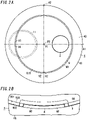
- the front wall portion 4B has a slit 9 provided through a front surface 40 thereof and recessed toward the base portion 4A as shown in FIGS. 1 and 2A .
- the slit 9 has: a sound hole H1 provided in a first region 91 of an inner surface 90 of the slit 9 to let the alarm sound come out of the housing 4; and a window hole H2 provided in a second region 92 of the inner surface 90 of the slit 9 to let the illuminating light come out of the housing 4.
- the sound hole H1 and the window hole H2 are provided through the inner surface 90 of the slit 9, thus making these holes less conspicuous. This contributes to evacuating a person in a shorter time while reducing the chances of affecting the cosmetic appearance of the audio device.
- the audio device 1 may be implemented as, for example, a battery-operated fire alarm. However, this is only an example of the present disclosure and should not be construed as limiting. Alternatively, the audio device 1 may also be implemented as a fire alarm which is electrically connected to an external power supply (such as a commercial power grid) and which is operated by converting AC power (with an effective voltage of 100 V, for example) supplied from the external power supply into a direct current.
- an external power supply such as a commercial power grid
- the audio device 1 is supposed to be installed on a ceiling surface (which is an exemplary surface of the structural component C1) of a bedroom in a resident's 100 dwelling house as shown in FIG. 6 .
- a ceiling surface which is an exemplary surface of the structural component C1
- the arrangement and operation of respective constituent elements of the audio device 1 in upward, downward, rightward, and leftward directions will be described as being defined by the up, down, right, and left arrows shown in FIG. 1 .
- the arrows indicating these directions are just shown there as an assistant to description and are insubstantial ones. It should also be noted that these directions do not define the direction in which the audio device 1 should be used.
- the audio device 1 includes not only the control unit 10, the first emission unit (sound emission unit) 11, the second emission unit (light emitting unit) 12, the detecting unit 2, and the housing 4 but also a battery 13, an operating unit 3, and an indicating lamp 15 as well.
- the audio device 1 is supposed to be implemented as an independently operating fire alarm with no capability of communicating with other fire alarms.
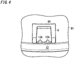
- the housing 4 houses the control unit 10, the first emission unit 11, the second emission unit 12, the battery 13, the detecting unit 2, and a circuit board B1 (see FIG. 4 ) on which the control unit 10 and other circuit components that form various other circuits are assembled together.
- the various other circuits include, for example, an audio circuit, a first lighting circuit, a second lighting circuit, and a power supply circuit as will be described later.
- the housing 4 is made of a synthetic resin and may be made of flame-retardant ABS resin, for example.
- the housing 4 is formed in the shape of a generally compressed cylinder.
- the housing 4 includes a case 4H, of which the upper end portion is open, and a base portion 4A.
- the base portion 4A is fitted to close the open upper end portion of the case 4H.
- the case 4H includes a front wall portion 4B (e.g., the lower wall portion in FIG. 1 ) and a sidewall portion 4C.
- the base portion 4A has a disk shape.
- the base portion 4A includes fixing portions, with which the base portion 4A is fixed onto a surface (installation surface) of the structural component C1.
- the base portion 4A has a plurality of through holes (fixing portions), which are provided to run through the base portion 4A in the thickness direction and to which mounting screws may be inserted such that the base portion 4A may be fixed with screws onto the ceiling surface. Fitting the base portion 4A into an upper end portion of the case 4H with the base portion 4A fixed onto the ceiling surface allows the base portion 4A and the case 4H to be assembled together.
- the front wall portion 4B has a disk shape and is located in front of (e.g., in FIG. 1 , under) the base portion 4A. As shown in FIGS. 1 and 2A , the front wall portion 4B has a slit 9, which is provided through the front surface 40 (e.g., the lower surface in FIG. 1 ) and recessed toward the base portion 4A (e.g., upward). As shown in FIG. 2A , when viewed from in front of the front wall portion 4B, the slit 9 has a shape extending along the outer periphery of the housing 4.
- the slit 9 when viewed from in front of the front wall portion 4B, the slit 9 may have the shape of a ring, of which one end and the other end along the outer periphery of the housing 4 are connected together (i.e., a closed ring shape).
- the front surface 40 of the front wall portion 4B has a region R10 surrounded with the slit 9 (see FIG. 2A ).
- the center P1 of region R10 agrees with the center of the outer periphery of the housing 4 when viewed from in front of the front wall portion 4B.
- the two centers “agree with each other,” the two centers do not have to exactly agree with each other but may generally agree with each other to the human eye.
- the slit 9 is formed in the shape of a circular ring with a predetermined groove width when viewed from in front of the front wall portion 4B (e.g., from under the front wall portion 4B in FIG. 1 ). That is to say, the slit 9 also has an annular appearance corresponding to the circular outer periphery of the housing 4 when viewed from in front of the housing 4.
- the slit 9 has a sound hole H1 and a window hole H2 respectively provided through a first region 91 and a second region 92 of its inner surface 90.
- the sound hole H1 is a hole to let the alarm sound, emitted from the first emission unit 11, to come out of the housing 4, and faces the first emission unit 11 in the housing 4.
- the window hole H2 is a hole to let the illuminating light, emitted from the second emission unit 12, come out of the housing 4, and faces the second emission unit 12 in the housing 4.
- the sound hole H1 and the window hole H2 in the slit 9 will be described in detail later in the "(2.8) Sound hole and window hole" section.
- a sidewall portion 4C protrudes from a peripheral edge E1 of the front wall portion 4B toward the base portion 4A as shown in FIG. 3 .
- the surface of the sidewall portion 4C is not straight in the upward/downward direction but is slightly tilted such that the diameter of the case 4H decreases toward the base portion 4A (i.e., upward) (see FIG. 3 ).
- the diameter at the lower end of the case 4H is slightly larger than the diameter at the upper end of the case 4H.
- the sidewall portion 4C has an opening 41 to let smoke involved with a fire flow into a labyrinth (i.e., a detection space of the detecting unit 2) provided inside the housing 4.
- the opening 41 is made up of a plurality of through holes arranged along the circumference of the housing 4.
- the housing 4 includes a partition wall that partitions the interior space thereof into upper and lower parts.
- the labyrinth and the detecting unit 2 are provided in the upper, first space and the control unit 10, the first emission unit 11, the second emission unit 12, the circuit board B1, and other components are provided in the lower, second space.
- the housing 4 further supports, on the front wall portion 4B, the operating unit 3 such that the lower surface of the operating unit 3 is exposed on the outer surface of the housing 4.
- the operating unit 3 accepts an operating command entered externally.
- the operating unit 3 is configured to be pushed upward by the user with one of his or her fingers, for example.
- the operating unit 3 is a disk member with a light-transmitting property and is arranged to face the indicating lamp 15 housed inside the housing 4.
- the operating unit 3 is configured to press down a push button switch (not shown) housed inside the housing 4 when subjected to a push operation.
- the operating unit 3 when viewed from in front of the front wall portion 4B, the operating unit 3 is arranged in the region R10 surrounded with the slit 9 on the front surface 40 of the front wall portion 4B. In this example, the operating unit 3 is arranged on the right of, and beside, the center P1 of the region R10.
- the first emission unit 11 emits a sound (i.e., an acoustic wave).
- a sound i.e., an acoustic wave.
- the control unit 10 determines that a fire should be present, the first emission unit 11 emits an alarm sound to alert the user to the presence of the fire.
- the first emission unit 11 may be implemented as a loudspeaker that transduces an electrical signal into a sound.
- the loudspeaker includes a diaphragm and emits an alarm sound by mechanically vibrating the diaphragm in accordance with the electrical signal.
- the loudspeaker is formed in the shape of a circular disk in a front view.
- the first emission unit 11 emits an alarm sound (such as a beep) under the control of the control unit 10.
- the first emission unit 11 suitably emits an alarm sound, of which the loudness (i.e., the sound pressure level) is variable.
- the alarm sound may include a sweep sound that is swept from a low-frequency sound to a high-frequency sound.
- the alarm sound may be accompanied with a voice warning message such as "Fire! Fire!”
- the alarm sound is supposed to be made up of the sweep sound and the voice warning message continuous with the sweep sound.
- the acoustic circuit includes a low-pass filter and an amplifier, for example.
- PWM pulse width modulation
- the acoustic circuit On receiving a pulse width modulation (PWM) signal corresponding to the alarm sound and generated by the control unit 10 at the outbreak of a fire, the acoustic circuit makes the low-pass filter transform the PWM signal into an audio signal with a sinusoidal waveform, makes the amplifier amplify the audio signal, and then makes the first emission unit 11 output the amplified signal as an alarm sound.
- PWM pulse width modulation
- the first emission unit 11 also emits the alarm sound tentatively even when subjected to an operation check test.
- the first emission unit 11 emits a voice warning message such as "Operating normally” or “Operating abnormally” according to the condition of the audio device 1.
- the operation check test may be carried out by either operating the operating unit 3 or pulling a pull string (not shown) extended from the housing 4.
- the first emission unit 11 may emit a voice warning message notifying the user that it is about time the battery 13 was replaced.
- the battery 13 may be a lithium-ion battery, for example.
- the second emission unit 12 emits illuminating light.
- the second emission unit 12 emits illuminating light that irradiates the surrounding region R1 in accordance with information provided about the fire under the control of the control unit 10.
- the second emission unit 12 includes, as a light source, a single or a plurality of illuminating white light-emitting diodes (LEDs) 12A mounted on the circuit board 1B (see FIG. 4 where two LEDs 12A are provided).
- the second emission unit 12 is OFF normally (i.e., while monitoring to see if any fire is present) and is turned ON (i.e., starts emitting the illuminating light) when the control unit 10 determines that a fire should be present.
- Each LED 12A may be implemented as a package LED in which at least one LED chip is mounted at the center of the mounting surface of a flat plate mounting board.
- the LED chip is suitably a blue light-emitting diode that radiates a blue ray out of the light-emitting surface thereof, for example.
- the mounting surface of the board including the LED chip is coated with an encapsulation resin to which a fluorescent material is added to convert the wavelength of the blue ray emitted from the LED chip.
- the LED 12A is configured to emit the white illuminating light from the light-emitting surface thereof when DC voltage is applied between the anode electrode and cathode electrode thereof.
- the color of the illuminating light does not have to be white but may also be any other color. Nevertheless, the color of the illuminating light is suitably different from the color of the light emitted from the indicating lamp 15.
- the circuit board 1B mounted are circuit components of the first lighting circuit for turning ON the LEDs 12A of the second emission unit 12.
- the first lighting circuit turns the LEDs 12A ON with the DC power discharged from the battery 13 under the control of the control unit 10. If the audio device 1 is electrically connected to a commercial power grid, then the first lighting circuit turns the LEDs 12A ON by converting the AC power supplied from the power grid into a DC current.
- the light (illuminating light) emitted from the second emission unit 12 is transmitted through a light guide member 8 (see FIG. 4 ) to come out of the housing 4.
- the light guide member 8 may be made of, for example, transparent acrylic resin.
- the light guide member 8 is formed in the shape of a bridge and mounted on the circuit board B1.
- An exposed portion 80 at the lower end of the light guide member 8 faces the two LEDs 12A.
- the exposed portion 80 is inserted into the window hole H2 from the circuit board B1 to be exposed through the window hole H2 (see FIG. 2B ).
- the light radiated from the LEDs 12A comes out of the window hole H2 through the exposed portion 80 of the light guide member 8 to irradiate the surrounding region R1 (e.g., the floor surface and bed in the bedroom in this example).
- the second emission unit 12 also emits light tentatively even when subjected to an operation check test. Just like the first emission unit 11, the second emission unit 12 may also be subjected to an operation check test by either pressing the operating unit 3 or pulling a pull string.
- the indicating lamp 15 includes, as its light source, a red LED 15A mounted on the circuit board B1 (see FIG. 5 ).
- the indicating lamp 15 is OFF normally (i.e., while monitoring to see if there is any fire present) but starts flickering (or is turned ON) when the control unit 10 determines that a fire should be present.
- the indicating lamp 15 stops flickering under the control of the control unit 10.
- circuit components of the second lighting circuit for flickering the LED 15A of the indicating lamp 15.
- the second lighting circuit flickers the LED 15A with the DC power discharged from the battery 13 under the control of the control unit 10. If the audio device 1 is electrically connected to a commercial power grid, then the second lighting circuit flickers the LED 15A by converting the AC power supplied from the power grid into a DC current.
- the light emitted from the indicating lamp 15 is transmitted through the operating unit 3 with light transmitting property to come out of the housing 4.
- the resident 100 is allowed to learn, by seeing the operating unit 3 flickering in red, that the audio device 1 is now in operation (i.e., detecting a fire).
- the indicating lamp 15 also flickers when subjected to an operation check test.
- the operation check test of the indicating lamp 15 may be carried out by either pressing the operating unit 3 or pulling a pull string just like the first emission unit 11.
- the indicating lamp 15 also flickers when it is about time the battery 13 was replaced or when the audio device 1 is out of order. If the operating unit 3 is operated while the indicating lamp 15 is flickering, the first emission unit 11 emits a voice warning message that it is about time the battery was replaced or that the audio device 1 has gone out of order.
- the detecting unit 2 detects the outbreak of a fire as a particular event.
- the detecting unit 2 may be implemented as, for example, a photoelectric sensor for detecting smoke (i.e., a smoke detecting unit).
- the detecting unit 2 includes a light-emitting unit 21 such as an LED and a photodetector unit 22 such as a photodiode, for example.
- the light-emitting unit 21 and the photodetector unit 22 are arranged in the labyrinth of the housing 4 such that the photosensitive plane of the photodetector unit 22 is off the optical axis of the light emitted from the light-emitting element 21.
- smoke may flow into the labyrinth through the opening 41 provided through the sidewall portion 4C of the housing 4.
- the detecting unit 2 makes the photodetector unit 22 receive the light emitted from the light-emitting unit 21 which has been scattered by the smoke.
- the detecting unit 2 is electrically connected to the control unit 10.
- the detecting unit 2 transmits an electrical signal (detection signal), indicating a voltage level corresponding to the quantity of the light received by the photodetector unit 22, to the control unit 10.
- the control unit 10 determines, by converting the quantity of light represented by the detection signal received from the detecting unit 2 into the concentration of smoke (as an exemplary event level), whether or not any fire is present.
- the detecting unit 2 may convert the quantity of the light received by the photodetector unit 22 into a smoke concentration and then transmit a detection signal indicating a voltage level corresponding to the smoke concentration to the control unit 10.
- the detecting unit 2 may determine, based on the quantity of the light received at the photodetector unit 22, that a fire (smoke) should be present and then transmit a detection signal, including information about the outbreak of the fire, to the control unit 10.
- the control unit 10 may be implemented as, for example, a microcomputer including, as major constituent elements, a central processing unit (CPU) and a memory. That is to say, the control unit 10 is implemented as a computer including a CPU and a memory. The computer performs the function of the control unit 10 by making the CPU execute a program stored in the memory. In this embodiment, the program is stored in advance in the memory. However, this is only an example and should not be construed as limiting. The program may also be downloaded via a telecommunications line such as the Internet or distributed after having been stored in a non-transitory storage medium such as a memory card.
- a telecommunications line such as the Internet
- a non-transitory storage medium such as a memory card.
- the control unit 10 controls the first emission unit 11, the acoustic circuit, the second emission unit 12, the indicating lamp 15, the first lighting circuit, the second lighting circuit, the detecting unit 2, and other units.
- the control unit 10 also controls a power supply circuit for generating, based on the DC power supplied from the battery 13, operating power for various types of circuits.
- the control unit 10 is configured to determine, in accordance with information provided about a fire as a particular event, whether or not any fire is present. Specifically, the control unit 10 monitors the level of the detection signal (information) received from the detecting unit 2 to determine whether or not the event level included in the detection signal has exceeded a threshold value.
- the event level may be, for example, the converted smoke concentration as described above. Alternatively, the event level may also be the quantity of light.
- the control unit 10 stores the threshold value in its own memory.
- the control unit 10 may determine, at regular time intervals, whether or not the smoke concentration has exceeded the threshold value, and may determine, when finding the smoke concentration greater than the threshold value at least once, that a fire should be present.
- the regular time interval may be 5 seconds, for example.
- the control unit 10 may count the number of times the smoke concentration has exceeded the threshold value consecutively, and may determine, on finding the number of times reaching a predetermined number of times, that a fire should be present.
- the control unit 10 may directly determine, on receiving a detection signal including information about the outbreak of a fire from the detecting unit 2, that a fire should be present.
- the control unit 10 On determining, based on the smoke concentration, that a fire should be present, the control unit 10 makes the first emission unit 11 start emitting an alarm sound. Specifically, the control unit 10 generates a PWM signal corresponding to a sweep sound, of which the frequency changes linearly with the passage of time, and outputs the PWM signal to the acoustic circuit. The PWM signal is converted by the acoustic circuit into an audio signal so that a sweep sound (as an alarm sound) is emitted from the first emission unit 11. In addition, the control unit 10 also generates, based on message data stored in its own memory, a PWM signal corresponding to the voice warning message and outputs the PWM signal to the acoustic circuit. The PWM signal is converted by the acoustic circuit into an audio signal so that a voice warning message (with an alarm sound) is emitted from the first emission unit 11.
- the control unit 10 On determining that a fire should be present, the control unit 10 transmits a control signal to turn the second emission unit 12 ON to the first lighting circuit and also transmits a control signal to flicker the indicating lamp 15 to the second lighting circuit.
- the first lighting circuit turns the second emission unit 12 ON so that the second emission unit 12 emits light with constant brightness.
- the second lighting circuit makes the indicating lamp 15 start flickering.
- the control unit 10 also continues determining the smoke concentration even while the fire alarm is being sounded (i.e., while an alarm sound is being emitted).
- the control unit 10 stops generating the PWM signal to instruct the first emission unit 11 to stop emitting the alarm sound.
- the control unit 10 also transmits a stop signal to the first lighting circuit and the second lighting circuit to stop emitting light from the second emission unit 12 and the indicating lamp 15.
- the control unit 10 automatically stops emitting the alarm sound, stops emitting the illuminating light, and stops flickering the indicating lamp 15.
- the control unit 10 stops emitting the alarm sound. If the resident 100 determines that the alarm should be being sounded by the audio device 1 by mistake, then he or she may stop emitting the alarm sound by performing the push operation on the operating unit 3. The resident 100 may also stop emitting the alarm sound by pulling the pull string.
- the control unit 10 carries out a predetermined type of test to check the operation.
- the operation check test includes, for example, a sound emission test on the first emission unit 11, a light emission test on the second emission unit 12, and a flickering light test on the indicating lamp 15.
- the operation check test may also be performed by pulling the pull string.
- the audio device 1 emits not only the alarm sound but also the illuminating light from the second emission unit 12, thus increasing the chances of the resident 100 instantly sensing the route (evacuation route) from the bed to the door leading to the hallway and saving him or her the time and effort to turn the bedroom light ON.
- the illuminating light emitted from the second emission unit 12 increases the chances of even a resident 100 who is a hearing-impaired person sensing the presence of a fire.
- the audio device 1 contributes to evacuating the resident 100 in a shorter time by emitting not only the alarm sound but also the illuminating light as well.
- the sound hole H1 and the window hole H2 are respectively arranged in the first region 91 and second region 92 of the inner surface 90 of the annular slit 9 with a predetermined groove width.
- a cross section, taken along a plane aligned with a radial direction defined with respect to a front wall portion 4B, for example, of the slit 9 according to this embodiment forms a rectangular recess and the first region 91 and second region 92 form respective parts of the bottom surface 900 (see FIG. 2B ) of the inner surface 90.
- the sound hole H1 and the window hole H2 are located at viewable positions.
- At least one of the first region 91 or the second region 92 may form part of either a first inner surface 901 (see FIG. 2B ), facing the center P1 of the region R10, of the inner surface 90 or a second inner surface 902 (see FIG. 2B ), facing the edge E1, of the inner surface 90.
- at least one of the first region 91 or the second region 92 may be a region overlapping with the bottom surface 900 and the first inner surface 901 (or the second inner surface 902) or may also be a region covering all of the bottom surface 900, the first inner surface 901, and the second inner surface 902.
- the cross section of the slit 9 does not have to be a rectangular recess but may also be a V-notch, for example.
- each of the sound hole H1 and the window hole H2 is provided through the bottom surface 900 of the slit 9 as described above, and their width is equal to that of the slit 9.
- each of the sound hole H1 and the window hole H2 has a curved arc shape that forms part of a circle, of which the center agrees with the center P1 of the region R10, according to the shape of the bottom surface 900 of the slit 9.
- the sound hole H1 and the window hole H2 define opening areas having the same shape and the same dimensions.
- the circumferential length of each of the sound hole H1 and the window hole H2 may be generally equal to the diameter of the operating unit 3 when viewed from in front of the front wall portion 4B, for example.
- each of the sound hole H1 and the window hole H2 may be about one-third or one quarter of the circumferential length of the slit 9, for example.
- the sound hole H1 is provided such that when viewed from in front of the front wall portion 4B, the sound hole HI, the center PI, and the operating unit 3 are arranged generally in line as shown in FIG. 2A (as indicated by the virtual line A1 in FIG. 2A ).
- the window hole H2 is provided on another virtual line A2 that intersects with the virtual line A1 at right angles and that passes through the center P1.
- the window hole H2 is located backward of the center P1.
- the window hole H2 may be located forward of the center P1.
- the relative locations of the sound hole HI, the window hole H2, the center PI, and the operating unit 3 illustrated in FIG. 2A are also exemplary ones.
- the locations of the sound hole H1 and the window hole H2 may be interchanged with each other.
- the window hole H2 may be provided on the virtual line A1 and beside and on the right of the operating unit 3.
- the sound hole H1 and the window hole H2 are provided through the inner surface 90 of the slit 9, thus making these holes less conspicuous. That is to say, this reduces the chances of giving an impression on the viewer that the sound hole H1 and the window hole H2 are outstanding against the structural component C1 when the audio device 1 is installed on the structural component C1 such as the ceiling of a dwelling house, for example. This contributes to evacuating the resident 100 in an even shorter time while reducing the chances of affecting the appearance of the audio device 1.
- the audio device 1 is not always installed on a ceiling surface but may also be installed on a wall surface as well. In that case, providing the sound hole H1 and the window hole H2 through the inner surface 90 of the slit 9 reduces the chances of dust and other foreign particles entering the housing 4 through these holes.
- forming the slit 9 in a shape extending along the outer periphery of the housing 4 provides the slit 9 that would give the user a sense of unity with the housing 4, thus making the sound hole H1 and the window hole H2 even less conspicuous.
- the center P1 of the region R10 surrounded with the slit 9 agrees with the center of the outer periphery of the housing 4 when viewed from in front of the front wall portion 4B. This provides a slit 9 that would give the user an enhanced sense of unity with the housing 4.
- the operating unit 3 is arranged in the region R10 surrounded with the slit 9 when viewed from in front of the front wall portion 4B. This provides a slit 9 that would give the user a sense of unity with the housing 4 and the operating unit 3. In addition, this also makes the sound hole H1 and the window hole H2 even less conspicuous.
- the slit 9 is formed in an annular shape, thus providing a slit 9 that would give the user an enhanced sense of unity with the housing 4.
- the outer periphery of the housing 4 has a circular shape and the slit 9 has an annular shape, which forms a circle concentric with the outer periphery of the housing 4, thus providing a slit 9 that would give the user an enhanced sense of unity.
- the relative locations and dimensions of the sound hole and the window hole should be designed such that the sound hole and the window hole are as inconspicuous as possible with respect to the front surface 40 of the front wall portion 4B. This would limit the flexibility of design.
- providing the slit 9 as is done in this embodiment allows the flexibility of design of the sound hole H1 and the window hole H2 to be increased. This is because restrictions on their locations with respect to the first region 91 and the second region 92 and their circumferential lengths will be relaxed as long as the sound hole H1 and the window hole H2 are provided through the inner surface 90 of the slit 9.
- the exposed portion 80 of the light guide member 8 is inserted into the window hole H2 from the circuit board B1 as described above.
- the exposed portion 80 has generally the same shape (i.e., a curved arc shape) as the opening area of the window hole H2 and also has a slightly smaller dimension than the opening area of the window hole H2 as shown in FIG. 2B .
- the surface (lower surface) of the exposed portion 80 is generally flush with the bottom surface 900 of the slit 9. This allows the light emitted from the second emission unit 12 to efficiently emerge out of the housing 4 through the exposed portion 80 of the light guide member 8 inserted into the window hole H2.
- the front surface 40 of the front wall portion 4B slopes away toward the base portion 4A as the distance from a center P2 thereof increases toward a peripheral edge E1 thereof. Specifically, in a side view of the housing 4, the front surface 40 has a gently curved shape and has its peak defined by the center P2. As used herein, the "center P2" of the front surface 40 agrees with the center P1 of the region R10 surrounded with the slit 9.
- the housing 4 looking thinner in the upward/downward direction in the vicinity of the peripheral edge E1 when the housing 4 is viewed as a whole, thus providing a housing 4 with a reduced thickness overall. Consequently, the audio device 1 with such a thin housing 4 is less conspicuous with respect to the structural component C1.
- the opening 41 of the sidewall portion 4C has, on at least one opening edge thereof, a tapered surface T1 to guide fire smoke such that the smoke flow into the housing 4 smoothly.
- the opening edge include a first edge 411 facing the base portion 4A and a second edge 412 facing the front wall portion 4B.
- the tapered surface T1 is provided for at least the second edge 412, out of the first edge 411 and the second edge 412.
- the tapered surface T1 is provided for each of the first edge 411 and the second edge 412.
- the lower tapered surface T1 is a sloped surface that slopes away toward the detection space (labyrinth) inside the housing 4 as the distance to the base portion 4A decreases.
- the upper tapered surface T1 is a sloped surface that slopes away toward the detection space (labyrinth) inside the housing 4 as the distance from the base portion 4A increases. Note that the lower tapered surface T1 has a larger area and a greater vertical length than the upper tapered surface T1.
- the sidewall portion 4C with such tapered surfaces T1 allows the fire smoke to flow into the detection space inside the housing 4 more smoothly, thus improving fire detection performance.
- the tapered surfaces T1 provided for both of the first edge 411 and the second edge 412 make the sidewall portion 4C looking constricted, thus improving the appearance of the audio device 1 as well.
- a portion D1 stretching from the lower end of the lower tapered surface T1 through the peripheral edge E1, of the sidewall portion 4C looks thin due to the presence of the tapered surface T1.
- the slit 9 has an annular shape when viewed from in front of the front wall portion 4B.
- the slit 9 may also have a polygonal ring shape, instead of the annular (circular ring) shape.
- the slit 9 may also have a regular hexagonal shape or a regular octagonal shape corresponding to its outer peripheral shape.
- the slit 9 has a shape corresponding to the outer peripheral shape of the housing 4.
- the shape of the slit 9 does not have to correspond to the outer peripheral shape of the housing 4.
- a slit 9 with a regular octagonal ring shape may be provided for the housing 4 with a circular outer peripheral shape.
- the number of the sound holes H1 provided and the number of the window holes H2 provided are both one. However, this is only an example of the present disclosure and should not be construed as limiting. Alternatively, their number may also be two or more. For example, two sound holes H1 may be arranged side by side along the circumference of the slit 9. For instance, two window holes H2 may be provided on the right and left ends of the slit 9 to interpose the center P1 between themselves. Still alternatively, the number of the sound holes H1 provided may be different from the number of the window holes H2 provided.
- the slit 9 has the shape of a single closed ring. However, the slit 9 does not have to have such a closed ring shape. Alternatively, the slit 9 may also have a partially open shape. For example, the slit 9 may have a C-shape, for example, when viewed from in front of the front wall portion 4B.
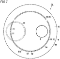
- the slit 9 may also be made up of a plurality of small slits 9X (e.g., two small slits 9X in the example illustrated in FIG. 7 ).
- the two small slits 9X are arranged along the outer periphery of the housing 4 when viewed from in front of the front wall portion 4B.
- This variation shown in FIG. 7 also makes the sound hole H1 and the window hole H2 less conspicuous.
- the sound hole H1 and the window hole H2 are both provided through one of the two C-shaped small slits 9X.
- one of these two holes H1 or H2 may be provided through the other small slit 9X.
- a single or a plurality of dummy slits may be provided separately from the slit 9.
- the dummy slit(s) may have the shape of a circular ring concentric with the slit 9, for example, and may have a smaller (or larger) diameter than the slit 9.
- the dummy slit(s) is/are arranged inside the slit 9. Providing such dummy slit(s) reduces the chances of giving the user an impression that the (main) slit 9 is provided with the sound hole H1 and the window hole H2.
- the audio device 1 according to the basic example is a fire alarm that operates independently. That is to say, the audio device 1 according to the basic example does not have the capability of communicating with other fire alarms. However, this is only an example of the present disclosure and should not be construed as limiting. Alternatively, the audio device 1 may also be an interconnected fire alarm with the capability of communicating with other fire alarms. In that case, the communication may be established either wirelessly or via cables, whichever is appropriate.
- the audio device 1 may also be configured to communicate with various types of devices other than fire alarms.
- Examples of those devices other than fire alarms include cellphones (such as smartphones) carried by the resident 100 with him or her and security monitoring devices installed in the dwelling house.
- an audio device (1, 1A) according to a first aspect is to be installed in a structural component (C1).
- the audio device (1, 1A) includes a control unit (10), a first emission unit (11), a second emission unit (12), and a housing (4).
- the control unit (10) determines, in accordance with information provided about a particular event, whether or not the particular event is present.
- the first emission unit (11) emits, when the control unit (10) determines that the particular event be present, a sound to alert a person to the presence of the particular event.
- the second emission unit (12) emits, in accordance with the information, illuminating light that irradiates a surrounding region (R1).
- the housing (4) houses the control unit (10), the first emission unit (11), and the second emission unit (12).
- the housing (4) includes: a base portion (4A) to be fixed onto the structural component (C1); and a front wall portion (4B) provided in front of the base portion (4A).
- the front wall portion (4B) has a slit (9) provided through a front surface (40) thereof and recessed toward the base portion (4A).
- the slit (9) has: a sound hole (H1) provided in a first region (91) of an inner surface (90) of the slit (9) to let the sound come out of the housing (4); and a window hole (H2) provided in a second region (92) of the inner surface (90) of the slit (9) to let the illuminating light come out of the housing (4).
- a sound i.e., an alarm sound
- the sound hole (H1) and the window hole (H2) are provided through the inner surface (90) of the slit (9), thus making these holes less conspicuous. This contributes to evacuating a person in a shorter time while reducing the chances of affecting the cosmetic appearance of the audio device.
- the slit (9) suitably has a shape extending along an outer periphery of the housing (4) when viewed from in front of the front wall portion (4B).
- the second aspect provides a slit (9) that would give the viewer a sense of unity with the housing (4), thus making the sound hole (H1) and the window hole (H2) even less conspicuous.
- the slit (9) suitably has a shape of a ring, one end and the other end of which along the outer periphery are connected together when viewed from in front of the front wall portion (4B).
- the third aspect provides a slit (9) that would give the viewer an enhanced sense of unity with the housing (4).
- the third aspect also increases the flexibility of design of the sound hole (H1) and the window hole (H2) in the slit (9).
- the slit (9) is suitably made up of a plurality of small slits (9X).
- the plurality of small slits (9X) are suitably arranged along the outer periphery when viewed from in front of the front wall portion (4B).
- the fourth aspect makes the sound hole (H1) and the window hole (H2) even less conspicuous.
- a center (PI) of a region (R10) surrounded with the slit (9) suitably agrees with a center of the outer periphery when viewed from in front of the front wall portion (4B).
- the fifth aspect provides a slit (9) that would give the viewer an enhanced sense of unity with the housing (4).
- An audio device (1, 1A) which may be implemented in conjunction with any one of the second to fifth aspects, suitably further includes an operating unit (3) to accept an operating command entered externally.
- the operating unit (3) is suitably arranged in a region (R10), surrounded with the slit (9), of the front surface (40) of the front wall portion (4B) when viewed from in front of the front wall portion (4B).
- the sixth aspect provides a slit (9) that would give the viewer a sense of unity with the housing (4) and the operating unit (3).
- the sixth aspect also makes the sound hole (H1) and the window hole (H2) even less conspicuous.
- the front surface (40) of the front wall portion (4B) suitably slopes away toward the base portion (4A) as a distance from a center (PI) thereof increases toward a peripheral edge (E1) thereof.
- the seventh aspect provides a housing (4) with a reduced thickness as a whole and also makes the audio device (1, 1A) less conspicuous with respect to the structural component (C1).
- the particular event may be a fire.
- the audio device (1, 1A) suitably further includes a detecting unit (2) housed in the housing (4) and configured to detect outbreak of the fire.
- the control unit (10) suitably determines whether or not the fire is present by being provided, as the information, with a result of detection by the detecting unit (2).
- the eighth aspect provides an audio device (1, 1A) with the detecting unit (2) that contributes to evacuating a person in an even shorter time while reducing the chances of affecting the cosmetic appearance.
- the detecting unit (2) is suitably a smoke detecting unit.
- the housing (4) suitably further includes a sidewall portion (4C) protruding from a peripheral edge (E1) of the front wall portion (4B) toward the base portion (4A).
- the sidewall portion (4C) suitably has an opening (41) to let smoke involved with the fire flow into a detection space of the smoke detecting unit (detecting unit 2) in the housing (4).
- the opening (41) suitably has, at an opening edge thereof, a tapered surface (T1) to guide the smoke involved with the fire such that the smoke flows into the detection space smoothly.
- the ninth aspect enhances the fire smoke detection performance by using the tapered surface (T1).
- the opening edge suitably has: a first edge (411) facing the base portion (4A); and a second edge (412) facing the front wall portion (4B).
- the tapered surface (T1) is suitably provided for at least the second edge (412), out of the first edge (411) and the second edge (412).
- the tenth aspect allows the tapered surface (T1) to reduce the thickness of the audio device (1, 1A ) as a whole from the peripheral edge (E1) through the second edge (412) of the front wall portion (4B), thereby improving the cosmetic appearance while enhancing the fire smoke detection performance.
- constituent elements according to the second to tenth aspects are not essential constituent elements for the audio device (1, 1A) but may be omitted as appropriate.
Landscapes
- Physics & Mathematics (AREA)
- General Physics & Mathematics (AREA)
- Engineering & Computer Science (AREA)
- Acoustics & Sound (AREA)
- Signal Processing (AREA)
- Chemical & Material Sciences (AREA)
- Analytical Chemistry (AREA)
- Business, Economics & Management (AREA)
- Emergency Management (AREA)
- Fire Alarms (AREA)
- Fire-Detection Mechanisms (AREA)
- Alarm Systems (AREA)
Applications Claiming Priority (3)
| Application Number | Priority Date | Filing Date | Title |
|---|---|---|---|
| JP2018066190A JP7002006B2 (ja) | 2018-03-29 | 2018-03-29 | 音響装置 |
| PCT/JP2019/010865 WO2019188420A1 (ja) | 2018-03-29 | 2019-03-15 | 音響装置 |
| EP19777224.7A EP3779907B1 (de) | 2018-03-29 | 2019-03-15 | Audiovorrichtung |
Related Parent Applications (2)
| Application Number | Title | Priority Date | Filing Date |
|---|---|---|---|
| EP19777224.7A Division-Into EP3779907B1 (de) | 2018-03-29 | 2019-03-15 | Audiovorrichtung |
| EP19777224.7A Division EP3779907B1 (de) | 2018-03-29 | 2019-03-15 | Audiovorrichtung |
Publications (1)
| Publication Number | Publication Date |
|---|---|
| EP4089656A1 true EP4089656A1 (de) | 2022-11-16 |
Family
ID=68061503
Family Applications (2)
| Application Number | Title | Priority Date | Filing Date |
|---|---|---|---|
| EP22175814.7A Withdrawn EP4089656A1 (de) | 2018-03-29 | 2019-03-15 | Audiovorrichtung |
| EP19777224.7A Active EP3779907B1 (de) | 2018-03-29 | 2019-03-15 | Audiovorrichtung |
Family Applications After (1)
| Application Number | Title | Priority Date | Filing Date |
|---|---|---|---|
| EP19777224.7A Active EP3779907B1 (de) | 2018-03-29 | 2019-03-15 | Audiovorrichtung |
Country Status (4)
| Country | Link |
|---|---|
| EP (2) | EP4089656A1 (de) |
| JP (1) | JP7002006B2 (de) |
| TW (1) | TWI712996B (de) |
| WO (1) | WO2019188420A1 (de) |
Citations (3)
| Publication number | Priority date | Publication date | Assignee | Title |
|---|---|---|---|---|
| JP2010049604A (ja) | 2008-08-25 | 2010-03-04 | Hochiki Corp | 警報器 |
| US20170138563A1 (en) * | 2015-11-13 | 2017-05-18 | Huizhou Light Engine Limited | Light emitting diode strobe lighting system |
| US20170358188A1 (en) * | 2016-06-10 | 2017-12-14 | Dathan O. Black | Systems including a smart device for receiving a prerecorded message and transmitting the prerecorded message to a detector |
Family Cites Families (7)
| Publication number | Priority date | Publication date | Assignee | Title |
|---|---|---|---|---|
| JPH0730991A (ja) * | 1993-07-13 | 1995-01-31 | Fujitsu Ltd | スピーカの取付構造 |
| JP4901572B2 (ja) * | 2007-04-27 | 2012-03-21 | Dxアンテナ株式会社 | 電子機器における押しボタン構造 |
| US20100073172A1 (en) * | 2008-09-25 | 2010-03-25 | L.I.F.E. Support Technologies, Llc | Dual condition fire/smoke detector with adjustable led cannon |
| US8933811B2 (en) * | 2009-10-05 | 2015-01-13 | Cavius Aps | Smoke alarm |
| US9007222B2 (en) * | 2012-09-21 | 2015-04-14 | Google Inc. | Detector unit and sensing chamber therefor |
| TWM505665U (zh) * | 2015-03-13 | 2015-07-21 | Yun Yang Fire Safety Equipment Co Ltd | 火災警報裝置 |
| JP6618765B2 (ja) * | 2015-10-27 | 2019-12-11 | ホーチキ株式会社 | 表示灯装置 |
-
2018
- 2018-03-29 JP JP2018066190A patent/JP7002006B2/ja active Active
-
2019
- 2019-03-15 EP EP22175814.7A patent/EP4089656A1/de not_active Withdrawn
- 2019-03-15 EP EP19777224.7A patent/EP3779907B1/de active Active
- 2019-03-15 WO PCT/JP2019/010865 patent/WO2019188420A1/ja not_active Ceased
- 2019-03-22 TW TW108109971A patent/TWI712996B/zh active
Patent Citations (3)
| Publication number | Priority date | Publication date | Assignee | Title |
|---|---|---|---|---|
| JP2010049604A (ja) | 2008-08-25 | 2010-03-04 | Hochiki Corp | 警報器 |
| US20170138563A1 (en) * | 2015-11-13 | 2017-05-18 | Huizhou Light Engine Limited | Light emitting diode strobe lighting system |
| US20170358188A1 (en) * | 2016-06-10 | 2017-12-14 | Dathan O. Black | Systems including a smart device for receiving a prerecorded message and transmitting the prerecorded message to a detector |
Also Published As
| Publication number | Publication date |
|---|---|
| EP3779907A4 (de) | 2021-05-19 |
| TWI712996B (zh) | 2020-12-11 |
| EP3779907A1 (de) | 2021-02-17 |
| JP7002006B2 (ja) | 2022-01-20 |
| TW201942880A (zh) | 2019-11-01 |
| EP3779907B1 (de) | 2022-07-06 |
| WO2019188420A1 (ja) | 2019-10-03 |
| JP2019175395A (ja) | 2019-10-10 |
Similar Documents
| Publication | Publication Date | Title |
|---|---|---|
| JP7555055B2 (ja) | 警報器、制御方法、及びプログラム | |
| JP7706097B2 (ja) | 警報器 | |
| EP3832615B1 (de) | Katastrophenbereitschaftsvorrichtung, steuerverfahren und programm | |
| EP3779907B1 (de) | Audiovorrichtung | |
| TWI746946B (zh) | 音響裝置、控制方法及程式 | |
| JP7213473B2 (ja) | 音響装置 | |
| KR102161846B1 (ko) | 융복합형 스마트 led 조명장치 및 이를 포함하는 스마트 조명 관제시스템 | |
| JP2020021262A (ja) | 警報システム、警報器、制御方法、及びプログラム | |
| JP7270205B2 (ja) | 制御システム、警報システム、プログラム及び制御方法 | |
| JP7511190B2 (ja) | 機器 | |
| TWI702573B (zh) | 音響裝置、音響裝置之控制方法及音響裝置之控制程式 | |
| JP7122705B2 (ja) | 防災機器、防災システム、制御方法、及びプログラム | |
| KR20160072608A (ko) | 센서유닛의 탈부착이 가능한 led 조명장치 |
Legal Events
| Date | Code | Title | Description |
|---|---|---|---|
| PUAI | Public reference made under article 153(3) epc to a published international application that has entered the european phase |
Free format text: ORIGINAL CODE: 0009012 |
|
| STAA | Information on the status of an ep patent application or granted ep patent |
Free format text: STATUS: REQUEST FOR EXAMINATION WAS MADE |
|
| 17P | Request for examination filed |
Effective date: 20220527 |
|
| AC | Divisional application: reference to earlier application |
Ref document number: 3779907 Country of ref document: EP Kind code of ref document: P |
|
| AK | Designated contracting states |
Kind code of ref document: A1 Designated state(s): AL AT BE BG CH CY CZ DE DK EE ES FI FR GB GR HR HU IE IS IT LI LT LU LV MC MK MT NL NO PL PT RO RS SE SI SK SM TR |
|
| STAA | Information on the status of an ep patent application or granted ep patent |
Free format text: STATUS: THE APPLICATION IS DEEMED TO BE WITHDRAWN |
|
| 18D | Application deemed to be withdrawn |
Effective date: 20230526 |