EP4089708B1 - Mehrfach verbindender betätigungshebel für schutzschalter - Google Patents
Mehrfach verbindender betätigungshebel für schutzschalter Download PDFInfo
- Publication number
- EP4089708B1 EP4089708B1 EP21844613.6A EP21844613A EP4089708B1 EP 4089708 B1 EP4089708 B1 EP 4089708B1 EP 21844613 A EP21844613 A EP 21844613A EP 4089708 B1 EP4089708 B1 EP 4089708B1
- Authority
- EP
- European Patent Office
- Prior art keywords
- handle
- linkage
- circuit breaker
- concealed
- intermittent
- Prior art date
- Legal status (The legal status is an assumption and is not a legal conclusion. Google has not performed a legal analysis and makes no representation as to the accuracy of the status listed.)
- Active
Links
Images


Classifications
-
- H—ELECTRICITY
- H01—ELECTRIC ELEMENTS
- H01H—ELECTRIC SWITCHES; RELAYS; SELECTORS; EMERGENCY PROTECTIVE DEVICES
- H01H71/00—Details of the protective switches or relays covered by groups H01H73/00 - H01H83/00
- H01H71/10—Operating or release mechanisms
- H01H71/1009—Interconnected mechanisms
-
- H—ELECTRICITY
- H01—ELECTRIC ELEMENTS
- H01H—ELECTRIC SWITCHES; RELAYS; SELECTORS; EMERGENCY PROTECTIVE DEVICES
- H01H71/00—Details of the protective switches or relays covered by groups H01H73/00 - H01H83/00
- H01H71/10—Operating or release mechanisms
- H01H71/50—Manual reset mechanisms which may be also used for manual release
- H01H71/52—Manual reset mechanisms which may be also used for manual release actuated by lever
- H01H71/521—Details concerning the lever handle
-
- H—ELECTRICITY
- H01—ELECTRIC ELEMENTS
- H01H—ELECTRIC SWITCHES; RELAYS; SELECTORS; EMERGENCY PROTECTIVE DEVICES
- H01H71/00—Details of the protective switches or relays covered by groups H01H73/00 - H01H83/00
- H01H71/10—Operating or release mechanisms
- H01H71/1009—Interconnected mechanisms
- H01H71/1018—Interconnected mechanisms with only external interconnections
-
- H—ELECTRICITY
- H01—ELECTRIC ELEMENTS
- H01H—ELECTRIC SWITCHES; RELAYS; SELECTORS; EMERGENCY PROTECTIVE DEVICES
- H01H83/00—Protective switches, e.g. circuit-breaking switches, or protective relays operated by abnormal electrical conditions otherwise than solely by excess current
- H01H83/20—Protective switches, e.g. circuit-breaking switches, or protective relays operated by abnormal electrical conditions otherwise than solely by excess current operated by excess current as well as by some other abnormal electrical condition
- H01H83/22—Protective switches, e.g. circuit-breaking switches, or protective relays operated by abnormal electrical conditions otherwise than solely by excess current operated by excess current as well as by some other abnormal electrical condition the other condition being imbalance of two or more currents or voltages
Definitions
- the present invention relates to the technical field of circuit breakers, and specifically, to a multi-linkage handle used in a circuit breaker.
- RCBO also called earth leakage circuit breaker or ground fault circuit interrupter
- the RCBO is mainly used to protect a person in danger when current leakage occurs in a device, and may be used to protect a line or a motor to avoid overload or short circuit, or may be used in normal cases when a line is infrequently converted and started.
- the RCBO usually includes a housing.
- a circuit breaker apparatus and a current leakage protection apparatus are distributed in the housing.
- the circuit breaker apparatus is used to control the connection or the disconnection of a movable contact and a fixed contact when a short circuit or an overload occurs or a line is infrequently started.
- the current leakage protection apparatus is used to control the connection or disconnection of the movable contact and the fixed contact when current leakage occurs.
- the circuit breaker apparatus and the current leakage protection apparatus are separately provided with a handle, so that when two or more circuit breakers are disposed, a quantity of handles also increases.
- a handle usually one handle controls one circuit breaker operation mechanism. In this way, the quantity of the handles increases, and when there are multiple circuit breakers, it is difficult to simultaneously control the handles manually, and the handles need to be closed one by one, leading to complicated operation.
- Such a handle is known e.g. from the document CN 108 511 281 A .
- the present invention provides a multi-linkage handle used in a circuit breaker, in which one handle may control two circuit breaker operation mechanisms, thereby reducing the quantity of operation handles and saving space.
- a multi-linkage handle used in a circuit breaker including a first handle, where a hinging and linking shaft hinged to a housing of the circuit breaker is linked to the middle part of the first handle, the other end of the hinging and linking shaft corresponding to the end linked to the first handle is linked to a concealed handle, an intermittent linkage mechanism is disposed between the concealed handle and the first handle, and the concealed handle may be intermittently linked to the first handle through the intermittent linkage mechanism.
- the structure of the handle is improved.
- the first handle, the concealed handle, and the intermittent linkage mechanism are disposed, so that multiple circuit breakers may be controlled by controlling the first handle, and further, one handle may control two circuit breaker operation mechanisms. In this way, a quantity of operation handles is reduced, the structure is simplified, and mounting space is reduced.
- the foregoing multi-linkage handle used in a circuit breaker is further set as follows.
- the intermittent linkage mechanism includes a second handle sleeved on the periphery of the concealed handle, the second handle is provided with an intermittent linkage area, and the concealed handle is provided with a protruding block corresponding to the intermittent linkage area; and the intermittent linkage mechanism further includes a connection assembly disposed between the first handle and the second handle, and the first handle may drive the second handle to work simultaneously through the connection assembly.
- the second handle may work simultaneously with the first handle through the connection assembly, so that one handle may control two circuit breakers.
- the circuit breaker apparatus may be intermittently linked to the current leakage protection apparatus according to an actual situation. For example, when current leakage does not occur, and the circuit breaker apparatus is normally started, the intermittent linkage area rotates in an effective rotation direction. In this case, the protruding block does not come into contact with the intermittent linkage area. The second handle rotates with the first handle until an end of the intermittent linkage area is close to the protruding block. Once an abnormal case, for example, current leakage occurs, the current leakage protection apparatus works. The concealed handle pushes an end of the intermittent linkage area through the protruding block, so that the second handle drives the first handle to rotate and power is off, thereby protecting the circuit.
- connection assembly includes a linkage rod with two ends oppositely fixed to the first handle and the second handle, respectively.
- the linkage rod is used to make the first handle and the second handles simultaneously linked.
- the foregoing multi-linkage handle used in a circuit breaker may further be set as follows.
- An indication block is disposed at the periphery of the first handle.
- the indication block may indicate power-on or power-off, facilitating observation for people.
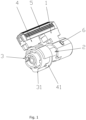
- a multi-linkage handle used in a circuit breaker shown in FIG. 1 to FIG. 4 includes a first handle 1.
- a hinging and linking shaft 2 hinged to a housing of the circuit breaker is linked to the middle part of the first handle 1 (where the linkage shaft 2 is a handle fixing axis extending from the housing).
- the other end of the hinging and linking shaft 2 corresponding to the end linked to the first handle 1 is linked to a concealed handle 3.
- An intermittent linkage mechanism is disposed between the concealed handle 3 and the first handle 1.
- the concealed handle 3 may be intermittently linked to the first handle 1 through the intermittent linkage mechanism.
- the intermittent linkage mechanism includes a second handle 4 sleeved on the periphery of the concealed handle 3.
- the second handle 4 is provided with an intermittent linkage area 41.
- the concealed handle 3 is provided with a protruding block 31 corresponding to the intermittent linkage area 41.
- the intermittent linkage mechanism further includes a connection assembly disposed between the first handle 1 and the second handle 4.
- the first handle 1 may drive the second handle 4 to work simultaneously through the connection assembly.
- the connection assembly includes a linkage rod 5 with two ends oppositely fixed to the first handle 1 and the second handle 4, respectively.
- An indication block 6 is disposed at the periphery of the first handle 1.
- the current leakage protection apparatus works and drives the concealed handle 3 to rotate in a direction opposite to the effective rotation direction of the first handle 1.
- the protruding block 31 pushes the end of the intermittent linkage area 41, so that the second handle 4 rotates with the concealed handle 3, and the linkage rod 5 drives the first handle 1 to rotate. In this way, power is off, and the circuit is protected.
- the structure of the handle is improved.
- the first handle 1, the concealed handle 3, and the intermittent linkage mechanism are disposed, so that multiple circuit breakers may be controlled by controlling the first handle 1, and further, one handle may control two circuit breaker operation mechanisms. In this way, a quantity of operation handles is reduced, the structure is simplified, and mounting space is reduced.
Landscapes
- Breakers (AREA)
Claims (3)
- Ein mehrgelenkiger Griff für einen Leistungsschalter, umfassend einen ersten Griff (1), wobei der mittlere Teil der ersten Griffes (1) mit einem Ende einer Scharnier- und Verbindungswelle (2), die an einem Gehäuse des Leistungsschalters eingehängt ist, koaxial und drehbar verbunden ist;
dadurch gekennzeichnet, dass er ferner einen verdeckten Griff (3) umfasst, der mit einem anderen Ende der Scharnier- und Verbindungswelle (2) verbunden werden kann, das dem Ende, das mit dem ersten Griff (1) verbunden werden kann, gegenüberliegt;
koaxial und drehbar ist ein intermittierender Verbindungsmechanismus zwischen dem verdeckten Griff (3) und dem ersten Griff (1) angeordnet, und der verdeckte Griff (3) ist durch den intermittierenden Verbindungsmechanismus intermittierend mit dem ersten Griff (1) verbunden, wobei der intermittierende Verbindungsmechanismus einen zweiten Griff (4), der eine Peripherie des verdeckten Griffes (3) ummantelt, koaxial und drehbar umfasst, der zweite Griff (4) mit einem intermittierenden Verbindungsbereich (41) und der verdeckte Griff (3) mit einem hervorstehenden Block (31), der dem intermittierenden Verbindungsbereich (41) entspricht, versehen ist; wobei der intermittierenden Verbindungsbereich (41) ferner eine Verbindungsanordnung (5) umfasst, die sich zwischen dem ersten Griff (1) und dem zweiten Griff (4) verbindet und der erste Griff (1) den zweiten Griff (4) antreibt, sodass sie durch die beide Verbindungsanordnung gleichzeitig den Betrieb aufnehmen. - Der mehrgelenkige Griff in einem Leistungsschalter nach Anspruch 1, wobei die Verbindungsanordnung eine Verbindungsstange (5) mit zwei gegenüberliegenden Enden umfasst, die jeweils am ersten Griff (1) bzw. am zweiten Griff (4) befestigt sind.
- Der mehrgelenkige Griff in einem Leistungsschalter nach Anspruch 1 oder 2, wobei ein Anzeigeblock (6) an der Peripherie des ersten Griffes (1) angeordnet ist.
Applications Claiming Priority (2)
| Application Number | Priority Date | Filing Date | Title |
|---|---|---|---|
| CN202120661910.XU CN214542093U (zh) | 2021-03-31 | 2021-03-31 | 一种断路器用多联动手柄 |
| PCT/CN2021/114978 WO2022205758A1 (zh) | 2021-03-31 | 2021-08-27 | 一种断路器用多联动手柄 |
Publications (4)
| Publication Number | Publication Date |
|---|---|
| EP4089708A1 EP4089708A1 (de) | 2022-11-16 |
| EP4089708A4 EP4089708A4 (de) | 2022-11-16 |
| EP4089708C0 EP4089708C0 (de) | 2023-11-15 |
| EP4089708B1 true EP4089708B1 (de) | 2023-11-15 |
Family
ID=78265740
Family Applications (1)
| Application Number | Title | Priority Date | Filing Date |
|---|---|---|---|
| EP21844613.6A Active EP4089708B1 (de) | 2021-03-31 | 2021-08-27 | Mehrfach verbindender betätigungshebel für schutzschalter |
Country Status (3)
| Country | Link |
|---|---|
| EP (1) | EP4089708B1 (de) |
| CN (1) | CN214542093U (de) |
| WO (1) | WO2022205758A1 (de) |
Families Citing this family (1)
| Publication number | Priority date | Publication date | Assignee | Title |
|---|---|---|---|---|
| CN115985727A (zh) * | 2022-12-12 | 2023-04-18 | 浙江科泰电气有限公司 | 一种具有可拆卸手柄套的操作机构及具有其的断路器 |
Family Cites Families (5)
| Publication number | Priority date | Publication date | Assignee | Title |
|---|---|---|---|---|
| US5648646A (en) * | 1995-06-19 | 1997-07-15 | Reliance Time Controls, Inc. | Circuit breaker linkage assembly |
| CN202772072U (zh) * | 2012-08-28 | 2013-03-06 | 乐清市荣凯电气有限公司 | 具有双极滚针的设备用断路器 |
| CN207624640U (zh) * | 2017-09-30 | 2018-07-17 | 江苏明及电气股份有限公司 | 一种用于断路器的隐藏式手柄结构 |
| CN208336119U (zh) * | 2018-07-23 | 2019-01-04 | 乐清市冉扬电气有限公司 | 两极漏电断路器 |
| CN211605056U (zh) * | 2020-02-28 | 2020-09-29 | 上海良信电器股份有限公司 | 剩余电流动作断路器 |
-
2021
- 2021-03-31 CN CN202120661910.XU patent/CN214542093U/zh active Active
- 2021-08-27 WO PCT/CN2021/114978 patent/WO2022205758A1/zh not_active Ceased
- 2021-08-27 EP EP21844613.6A patent/EP4089708B1/de active Active
Also Published As
| Publication number | Publication date |
|---|---|
| EP4089708A1 (de) | 2022-11-16 |
| CN214542093U (zh) | 2021-10-29 |
| WO2022205758A1 (zh) | 2022-10-06 |
| EP4089708C0 (de) | 2023-11-15 |
Similar Documents
| Publication | Publication Date | Title |
|---|---|---|
| EP4089707B1 (de) | 2p2m elektromagnetischer fehlerstrom leistungsschalter mit überstrom schutz | |
| EP4089708B1 (de) | Mehrfach verbindender betätigungshebel für schutzschalter | |
| CN113066702A (zh) | 一种紧凑型接地电路断路器及其使用方法 | |
| EP4089709B1 (de) | Betätigungsmechanismus eines elektromagnetischen reststromschutzschalters mit 2p2-modulus und überstromschutz | |
| NO349579B1 (en) | Electric leakage circuit breaker | |
| RU2683244C1 (ru) | Автоматический выключатель | |
| CN214063258U (zh) | 全压启动型消防泵应急启动装置 | |
| US10176956B2 (en) | Safety tripping device for a frame-type ACB drawer seat | |
| CN211788768U (zh) | 一种低压配电柜断路器的刀开关结构 | |
| CN119153267A (zh) | 一种真空断路器 | |
| CN219759495U (zh) | 防撞型智能弹操断路器 | |
| CN207441620U (zh) | 断路器操作装置中的触头系统及该操作装置 | |
| EP3706154A1 (de) | Niederspannungs-leistungsverteilungsvorrichtung und verfahren zur steuerung der auslösung einer niederspannungsleistungsverteilung | |
| KR100827957B1 (ko) | 누전 차단기의 자동복구 장치 | |
| BR9805692B1 (pt) | configuração de interruptor de circuito com uma função de desconexão e kit de peças. | |
| KR100311532B1 (ko) | 배전반의 접지 스위치 장치 | |
| US2204393A (en) | Auxiliary switch | |
| EP4089710B1 (de) | 2p2m fehlerstrom-schutzschalter mit elektromagnetischen überstrom schutz | |
| CN114038699A (zh) | 一种具有中性极重叠功能的双电源自动转换开关 | |
| CN114709115B (zh) | 断路器旋转机构 | |
| CN222867577U (zh) | 一种塑壳断路器 | |
| CN219476587U (zh) | 一种插入式断路器 | |
| CN218482172U (zh) | 一种断路器 | |
| CN222483213U (zh) | 联锁装置 | |
| CN209747371U (zh) | 断路器安全锁 |
Legal Events
| Date | Code | Title | Description |
|---|---|---|---|
| STAA | Information on the status of an ep patent application or granted ep patent |
Free format text: STATUS: UNKNOWN |
|
| STAA | Information on the status of an ep patent application or granted ep patent |
Free format text: STATUS: THE INTERNATIONAL PUBLICATION HAS BEEN MADE |
|
| PUAI | Public reference made under article 153(3) epc to a published international application that has entered the european phase |
Free format text: ORIGINAL CODE: 0009012 |
|
| STAA | Information on the status of an ep patent application or granted ep patent |
Free format text: STATUS: REQUEST FOR EXAMINATION WAS MADE |
|
| 17P | Request for examination filed |
Effective date: 20220127 |
|
| A4 | Supplementary search report drawn up and despatched |
Effective date: 20220912 |
|
| AK | Designated contracting states |
Kind code of ref document: A1 Designated state(s): AL AT BE BG CH CY CZ DE DK EE ES FI FR GB GR HR HU IE IS IT LI LT LU LV MC MK MT NL NO PL PT RO RS SE SI SK SM TR |
|
| GRAP | Despatch of communication of intention to grant a patent |
Free format text: ORIGINAL CODE: EPIDOSNIGR1 |
|
| STAA | Information on the status of an ep patent application or granted ep patent |
Free format text: STATUS: GRANT OF PATENT IS INTENDED |
|
| INTG | Intention to grant announced |
Effective date: 20230519 |
|
| GRAS | Grant fee paid |
Free format text: ORIGINAL CODE: EPIDOSNIGR3 |
|
| GRAA | (expected) grant |
Free format text: ORIGINAL CODE: 0009210 |
|
| STAA | Information on the status of an ep patent application or granted ep patent |
Free format text: STATUS: THE PATENT HAS BEEN GRANTED |
|
| DAV | Request for validation of the european patent (deleted) | ||
| DAX | Request for extension of the european patent (deleted) | ||
| AK | Designated contracting states |
Kind code of ref document: B1 Designated state(s): AL AT BE BG CH CY CZ DE DK EE ES FI FR GB GR HR HU IE IS IT LI LT LU LV MC MK MT NL NO PL PT RO RS SE SI SK SM TR |
|
| REG | Reference to a national code |
Ref country code: CH Ref legal event code: EP Ref country code: GB Ref legal event code: FG4D |
|
| REG | Reference to a national code |
Ref country code: DE Ref legal event code: R096 Ref document number: 602021006915 Country of ref document: DE |
|
| REG | Reference to a national code |
Ref country code: IE Ref legal event code: FG4D |
|
| U01 | Request for unitary effect filed |
Effective date: 20231123 |
|
| U07 | Unitary effect registered |
Designated state(s): AT BE BG DE DK EE FI FR IT LT LU LV MT NL PT SE SI Effective date: 20231129 |
|
| PG25 | Lapsed in a contracting state [announced via postgrant information from national office to epo] |
Ref country code: GR Free format text: LAPSE BECAUSE OF FAILURE TO SUBMIT A TRANSLATION OF THE DESCRIPTION OR TO PAY THE FEE WITHIN THE PRESCRIBED TIME-LIMIT Effective date: 20240216 |
|
| PG25 | Lapsed in a contracting state [announced via postgrant information from national office to epo] |
Ref country code: IS Free format text: LAPSE BECAUSE OF FAILURE TO SUBMIT A TRANSLATION OF THE DESCRIPTION OR TO PAY THE FEE WITHIN THE PRESCRIBED TIME-LIMIT Effective date: 20240315 |
|
| PG25 | Lapsed in a contracting state [announced via postgrant information from national office to epo] |
Ref country code: ES Free format text: LAPSE BECAUSE OF FAILURE TO SUBMIT A TRANSLATION OF THE DESCRIPTION OR TO PAY THE FEE WITHIN THE PRESCRIBED TIME-LIMIT Effective date: 20231115 |
|
| PG25 | Lapsed in a contracting state [announced via postgrant information from national office to epo] |
Ref country code: IS Free format text: LAPSE BECAUSE OF FAILURE TO SUBMIT A TRANSLATION OF THE DESCRIPTION OR TO PAY THE FEE WITHIN THE PRESCRIBED TIME-LIMIT Effective date: 20240315 Ref country code: GR Free format text: LAPSE BECAUSE OF FAILURE TO SUBMIT A TRANSLATION OF THE DESCRIPTION OR TO PAY THE FEE WITHIN THE PRESCRIBED TIME-LIMIT Effective date: 20240216 Ref country code: ES Free format text: LAPSE BECAUSE OF FAILURE TO SUBMIT A TRANSLATION OF THE DESCRIPTION OR TO PAY THE FEE WITHIN THE PRESCRIBED TIME-LIMIT Effective date: 20231115 |
|
| PG25 | Lapsed in a contracting state [announced via postgrant information from national office to epo] |
Ref country code: RS Free format text: LAPSE BECAUSE OF FAILURE TO SUBMIT A TRANSLATION OF THE DESCRIPTION OR TO PAY THE FEE WITHIN THE PRESCRIBED TIME-LIMIT Effective date: 20231115 Ref country code: PL Free format text: LAPSE BECAUSE OF FAILURE TO SUBMIT A TRANSLATION OF THE DESCRIPTION OR TO PAY THE FEE WITHIN THE PRESCRIBED TIME-LIMIT Effective date: 20231115 Ref country code: NO Free format text: LAPSE BECAUSE OF FAILURE TO SUBMIT A TRANSLATION OF THE DESCRIPTION OR TO PAY THE FEE WITHIN THE PRESCRIBED TIME-LIMIT Effective date: 20240215 Ref country code: HR Free format text: LAPSE BECAUSE OF FAILURE TO SUBMIT A TRANSLATION OF THE DESCRIPTION OR TO PAY THE FEE WITHIN THE PRESCRIBED TIME-LIMIT Effective date: 20231115 |
|
| PG25 | Lapsed in a contracting state [announced via postgrant information from national office to epo] |
Ref country code: CZ Free format text: LAPSE BECAUSE OF FAILURE TO SUBMIT A TRANSLATION OF THE DESCRIPTION OR TO PAY THE FEE WITHIN THE PRESCRIBED TIME-LIMIT Effective date: 20231115 |
|
| PG25 | Lapsed in a contracting state [announced via postgrant information from national office to epo] |
Ref country code: SK Free format text: LAPSE BECAUSE OF FAILURE TO SUBMIT A TRANSLATION OF THE DESCRIPTION OR TO PAY THE FEE WITHIN THE PRESCRIBED TIME-LIMIT Effective date: 20231115 |
|
| PG25 | Lapsed in a contracting state [announced via postgrant information from national office to epo] |
Ref country code: SM Free format text: LAPSE BECAUSE OF FAILURE TO SUBMIT A TRANSLATION OF THE DESCRIPTION OR TO PAY THE FEE WITHIN THE PRESCRIBED TIME-LIMIT Effective date: 20231115 Ref country code: SK Free format text: LAPSE BECAUSE OF FAILURE TO SUBMIT A TRANSLATION OF THE DESCRIPTION OR TO PAY THE FEE WITHIN THE PRESCRIBED TIME-LIMIT Effective date: 20231115 Ref country code: RO Free format text: LAPSE BECAUSE OF FAILURE TO SUBMIT A TRANSLATION OF THE DESCRIPTION OR TO PAY THE FEE WITHIN THE PRESCRIBED TIME-LIMIT Effective date: 20231115 Ref country code: CZ Free format text: LAPSE BECAUSE OF FAILURE TO SUBMIT A TRANSLATION OF THE DESCRIPTION OR TO PAY THE FEE WITHIN THE PRESCRIBED TIME-LIMIT Effective date: 20231115 |
|
| REG | Reference to a national code |
Ref country code: DE Ref legal event code: R097 Ref document number: 602021006915 Country of ref document: DE |
|
| U20 | Renewal fee for the european patent with unitary effect paid |
Year of fee payment: 4 Effective date: 20240712 |
|
| PLBE | No opposition filed within time limit |
Free format text: ORIGINAL CODE: 0009261 |
|
| STAA | Information on the status of an ep patent application or granted ep patent |
Free format text: STATUS: NO OPPOSITION FILED WITHIN TIME LIMIT |
|
| 26N | No opposition filed |
Effective date: 20240819 |
|
| REG | Reference to a national code |
Ref country code: CH Ref legal event code: PL |
|
| PG25 | Lapsed in a contracting state [announced via postgrant information from national office to epo] |
Ref country code: MC Free format text: LAPSE BECAUSE OF FAILURE TO SUBMIT A TRANSLATION OF THE DESCRIPTION OR TO PAY THE FEE WITHIN THE PRESCRIBED TIME-LIMIT Effective date: 20231115 Ref country code: CH Free format text: LAPSE BECAUSE OF NON-PAYMENT OF DUE FEES Effective date: 20240831 |
|
| PG25 | Lapsed in a contracting state [announced via postgrant information from national office to epo] |
Ref country code: IE Free format text: LAPSE BECAUSE OF NON-PAYMENT OF DUE FEES Effective date: 20240827 |
|
| U20 | Renewal fee for the european patent with unitary effect paid |
Year of fee payment: 5 Effective date: 20250819 |
|
| PG25 | Lapsed in a contracting state [announced via postgrant information from national office to epo] |
Ref country code: CY Free format text: LAPSE BECAUSE OF FAILURE TO SUBMIT A TRANSLATION OF THE DESCRIPTION OR TO PAY THE FEE WITHIN THE PRESCRIBED TIME-LIMIT; INVALID AB INITIO Effective date: 20210827 |
|
| PG25 | Lapsed in a contracting state [announced via postgrant information from national office to epo] |
Ref country code: HU Free format text: LAPSE BECAUSE OF FAILURE TO SUBMIT A TRANSLATION OF THE DESCRIPTION OR TO PAY THE FEE WITHIN THE PRESCRIBED TIME-LIMIT; INVALID AB INITIO Effective date: 20210827 |