EP4089794A2 - Batterieeinheit mit eingebauten mitteln zur temperaturkontrolle oder -regulierung - Google Patents
Batterieeinheit mit eingebauten mitteln zur temperaturkontrolle oder -regulierung Download PDFInfo
- Publication number
- EP4089794A2 EP4089794A2 EP22172437.0A EP22172437A EP4089794A2 EP 4089794 A2 EP4089794 A2 EP 4089794A2 EP 22172437 A EP22172437 A EP 22172437A EP 4089794 A2 EP4089794 A2 EP 4089794A2
- Authority
- EP
- European Patent Office
- Prior art keywords
- cells
- face
- surface element
- contact
- heat transfer
- Prior art date
- Legal status (The legal status is an assumption and is not a legal conclusion. Google has not performed a legal analysis and makes no representation as to the accuracy of the status listed.)
- Pending
Links
- 230000001105 regulatory effect Effects 0.000 title claims abstract description 5
- 230000001276 controlling effect Effects 0.000 title 1
- 239000013529 heat transfer fluid Substances 0.000 claims abstract description 33
- 238000001816 cooling Methods 0.000 claims abstract description 26
- 239000012530 fluid Substances 0.000 claims abstract description 24
- 230000000593 degrading effect Effects 0.000 claims abstract description 16
- 230000000295 complement effect Effects 0.000 claims abstract description 7
- 239000007788 liquid Substances 0.000 claims description 40
- 239000000463 material Substances 0.000 claims description 8
- 239000011810 insulating material Substances 0.000 claims description 4
- 238000004519 manufacturing process Methods 0.000 claims description 4
- 238000004026 adhesive bonding Methods 0.000 claims description 3
- 238000009826 distribution Methods 0.000 claims description 3
- 238000000034 method Methods 0.000 claims description 3
- 230000010354 integration Effects 0.000 claims description 2
- 238000005304 joining Methods 0.000 claims description 2
- 239000010410 layer Substances 0.000 description 5
- 230000000694 effects Effects 0.000 description 4
- WYTGDNHDOZPMIW-RCBQFDQVSA-N alstonine Natural products C1=CC2=C3C=CC=CC3=NC2=C2N1C[C@H]1[C@H](C)OC=C(C(=O)OC)[C@H]1C2 WYTGDNHDOZPMIW-RCBQFDQVSA-N 0.000 description 3
- 229910052782 aluminium Inorganic materials 0.000 description 3
- XAGFODPZIPBFFR-UHFFFAOYSA-N aluminium Chemical compound [Al] XAGFODPZIPBFFR-UHFFFAOYSA-N 0.000 description 3
- 230000005540 biological transmission Effects 0.000 description 3
- 230000015556 catabolic process Effects 0.000 description 3
- 238000006731 degradation reaction Methods 0.000 description 3
- 238000013507 mapping Methods 0.000 description 3
- 229910052751 metal Inorganic materials 0.000 description 3
- 239000002184 metal Substances 0.000 description 3
- 239000004033 plastic Substances 0.000 description 3
- 238000013461 design Methods 0.000 description 2
- 238000012986 modification Methods 0.000 description 2
- 230000004048 modification Effects 0.000 description 2
- 230000000284 resting effect Effects 0.000 description 2
- 239000012815 thermoplastic material Substances 0.000 description 2
- 238000012546 transfer Methods 0.000 description 2
- 238000011282 treatment Methods 0.000 description 2
- 229920012563 PP GF30 Polymers 0.000 description 1
- 229910000831 Steel Inorganic materials 0.000 description 1
- 230000032683 aging Effects 0.000 description 1
- 239000004411 aluminium Substances 0.000 description 1
- 238000013459 approach Methods 0.000 description 1
- 230000015572 biosynthetic process Effects 0.000 description 1
- 239000000470 constituent Substances 0.000 description 1
- 238000010276 construction Methods 0.000 description 1
- 239000002826 coolant Substances 0.000 description 1
- 239000012809 cooling fluid Substances 0.000 description 1
- 238000009792 diffusion process Methods 0.000 description 1
- 235000021183 entrée Nutrition 0.000 description 1
- 230000005484 gravity Effects 0.000 description 1
- 238000009434 installation Methods 0.000 description 1
- 229910001416 lithium ion Inorganic materials 0.000 description 1
- 238000000465 moulding Methods 0.000 description 1
- 238000005457 optimization Methods 0.000 description 1
- 229920000642 polymer Polymers 0.000 description 1
- QEVHRUUCFGRFIF-MDEJGZGSSA-N reserpine Chemical compound O([C@H]1[C@@H]([C@H]([C@H]2C[C@@H]3C4=C(C5=CC=C(OC)C=C5N4)CCN3C[C@H]2C1)C(=O)OC)OC)C(=O)C1=CC(OC)=C(OC)C(OC)=C1 QEVHRUUCFGRFIF-MDEJGZGSSA-N 0.000 description 1
- 239000002356 single layer Substances 0.000 description 1
- 239000010959 steel Substances 0.000 description 1
- 238000003860 storage Methods 0.000 description 1
- 238000006467 substitution reaction Methods 0.000 description 1
- 239000002470 thermal conductor Substances 0.000 description 1
- 238000003466 welding Methods 0.000 description 1
Images




Classifications
-
- H—ELECTRICITY
- H01—ELECTRIC ELEMENTS
- H01M—PROCESSES OR MEANS, e.g. BATTERIES, FOR THE DIRECT CONVERSION OF CHEMICAL ENERGY INTO ELECTRICAL ENERGY
- H01M10/00—Secondary cells; Manufacture thereof
- H01M10/60—Heating or cooling; Temperature control
- H01M10/61—Types of temperature control
- H01M10/613—Cooling or keeping cold
-
- H—ELECTRICITY
- H01—ELECTRIC ELEMENTS
- H01M—PROCESSES OR MEANS, e.g. BATTERIES, FOR THE DIRECT CONVERSION OF CHEMICAL ENERGY INTO ELECTRICAL ENERGY
- H01M10/00—Secondary cells; Manufacture thereof
- H01M10/60—Heating or cooling; Temperature control
- H01M10/61—Types of temperature control
- H01M10/617—Types of temperature control for achieving uniformity or desired distribution of temperature
-
- H—ELECTRICITY
- H01—ELECTRIC ELEMENTS
- H01M—PROCESSES OR MEANS, e.g. BATTERIES, FOR THE DIRECT CONVERSION OF CHEMICAL ENERGY INTO ELECTRICAL ENERGY
- H01M10/00—Secondary cells; Manufacture thereof
- H01M10/60—Heating or cooling; Temperature control
- H01M10/62—Heating or cooling; Temperature control specially adapted for specific applications
- H01M10/625—Vehicles
-
- H—ELECTRICITY
- H01—ELECTRIC ELEMENTS
- H01M—PROCESSES OR MEANS, e.g. BATTERIES, FOR THE DIRECT CONVERSION OF CHEMICAL ENERGY INTO ELECTRICAL ENERGY
- H01M10/00—Secondary cells; Manufacture thereof
- H01M10/60—Heating or cooling; Temperature control
- H01M10/65—Means for temperature control structurally associated with the cells
- H01M10/653—Means for temperature control structurally associated with the cells characterised by electrically insulating or thermally conductive materials
-
- H—ELECTRICITY
- H01—ELECTRIC ELEMENTS
- H01M—PROCESSES OR MEANS, e.g. BATTERIES, FOR THE DIRECT CONVERSION OF CHEMICAL ENERGY INTO ELECTRICAL ENERGY
- H01M10/00—Secondary cells; Manufacture thereof
- H01M10/60—Heating or cooling; Temperature control
- H01M10/65—Means for temperature control structurally associated with the cells
- H01M10/655—Solid structures for heat exchange or heat conduction
- H01M10/6556—Solid parts with flow channel passages or pipes for heat exchange
-
- H—ELECTRICITY
- H01—ELECTRIC ELEMENTS
- H01M—PROCESSES OR MEANS, e.g. BATTERIES, FOR THE DIRECT CONVERSION OF CHEMICAL ENERGY INTO ELECTRICAL ENERGY
- H01M10/00—Secondary cells; Manufacture thereof
- H01M10/60—Heating or cooling; Temperature control
- H01M10/65—Means for temperature control structurally associated with the cells
- H01M10/658—Means for temperature control structurally associated with the cells by thermal insulation or shielding
-
- H—ELECTRICITY
- H01—ELECTRIC ELEMENTS
- H01M—PROCESSES OR MEANS, e.g. BATTERIES, FOR THE DIRECT CONVERSION OF CHEMICAL ENERGY INTO ELECTRICAL ENERGY
- H01M2220/00—Batteries for particular applications
- H01M2220/20—Batteries in motive systems, e.g. vehicle, ship, plane
-
- Y—GENERAL TAGGING OF NEW TECHNOLOGICAL DEVELOPMENTS; GENERAL TAGGING OF CROSS-SECTIONAL TECHNOLOGIES SPANNING OVER SEVERAL SECTIONS OF THE IPC; TECHNICAL SUBJECTS COVERED BY FORMER USPC CROSS-REFERENCE ART COLLECTIONS [XRACs] AND DIGESTS
- Y02—TECHNOLOGIES OR APPLICATIONS FOR MITIGATION OR ADAPTATION AGAINST CLIMATE CHANGE
- Y02E—REDUCTION OF GREENHOUSE GAS [GHG] EMISSIONS, RELATED TO ENERGY GENERATION, TRANSMISSION OR DISTRIBUTION
- Y02E60/00—Enabling technologies; Technologies with a potential or indirect contribution to GHG emissions mitigation
- Y02E60/10—Energy storage using batteries
Definitions
- the present invention relates to the field of autonomous electrical energy sources, in particular those on board motor vehicles, and relates to a battery unit with integrated temperature control or regulation means and a hybrid or electric motor vehicle comprising at least one such unit.
- Hybrid/electric vehicles are equipped with a battery to store the electrical energy necessary for their operation.
- Current challenges require optimizing the design of battery units, also known as “battery packs”, in order to obtain the best performance in terms of service life (charge/discharge) and driving range. Charging time is also an important factor in the daily use of these battery packs.
- the batteries used ideally need to operate at temperatures between 10° C. and 30° C., in particular batteries with high storage density, of the Li-ion or Li-polymer type for example.
- a temperature that is too low affects the autonomy and a temperature that is too high affects the life of the batteries. It is therefore necessary to regulate the temperature of the batteries as well as possible.
- batteries are known with a casing made of thermoplastic material comprising a double bottom thermoregulated by circulation of heat transfer liquid and on which the battery cells rest.
- This double bottom comprises a thermally conductive wall which is contacted on one side by the heat transfer fluid and on the other by the cells.
- this double bottom can be in the form of a hollow plate (known under the designation "cooling plate” - cooling plate) consisting of two metal half-shells (for example aluminum) assembled together and having in the hollow volume at least one liquid circulation path between a supply inlet and at least one evacuation outlet.
- the circulation path generally in the form of a serpentine or a network of parallel channels, is configured to irrigate the entire surface of the plate wall in contact with the cells.
- the double bottom may be composed of several individual hollow plates side by side, each with its own circulation path and its inlets and outlets, optionally fluidly connected to one another and each supporting a battery module grouping together several cells.
- the double bottom may consist of a thermally conductive plate, in particular metal, directly attached to the bottom of the plastic case with the formation of at least one liquid fluid circulation path between them, connecting at least one inlet to at least one output.
- Such substantially uniform temperature regulation is not possible with point or multi-point supplies and evacuations as mentioned above (that is to say by one or more localized inlets and outlets of liquid heat transfer fluid) and which generate at least one super-cooled area or cold and/or at least one sub-refrigerated or hot zone, or at best a significant temperature variation gradient, with a differential between extreme temperatures exceeding the aforementioned maximum value.
- the main object of the present invention is to provide a solution to the aforementioned drawbacks and expectations.
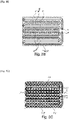
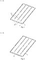
- the figure 1 and 8 and partially figures 2 to 7 show a battery unit 1, in particular for a hybrid and/or electric motor vehicle, essentially comprising, on the one hand, a plurality of cells 2 or battery elements, where appropriate grouped together physically and/or electrically in several blocks or modules 2', on the other hand, a casing 3 housing said cells or elements 2 and, finally, means for regulating the temperature of said cells or elements 2 by circulation of fluid FC coolant.
- These regulation means comprise, at the level of a bottom region 4 of the casing 3 on which the cells 2 rest, at least one, preferably several, zone(s) 5 for heat exchange between the said cells 2 and the heat transfer fluid FC .
- each zone 5 (a zone for the entire battery unit or a zone for each of the modules constituting the unit) comprises a surface element 6 with high thermal conductivity, preferably metallic, which is in contact on a first face 6' with cells 2 and in contact on its second face 6" with the heat transfer fluid FC, and which delimits with another complementary surface element 7, or with the bottom wall 3' of the casing 3 or a part of the latter, a plate cooling 5 'with an interstitial circulation volume 8, advantageously integrating at least one circulation path or network 8' formed of channel portions 8", with at least one supply inlet 9 and at least one evacuation outlet 9 'Cooling fluid, preferably liquid.
- the or each cooling plate 5' can be formed either by assembling two metallic surface elements 6 and 7, for example a flat plate and a hollow shell, or by assembling a metallic surface element 6 with the wall bottom 3' hollowed out of the case 3, made of plastic material for example (as disclosed by the WO documents cited in the introduction).
- each cell 2 rests on the face 6' of a surface element 6, and thus all the cells 2 rest on a cooling plate 5' of a heat exchange zone 5, arranged at the bottom of the case 3, which forms a sealed structure, and are arranged in a single layer.
- the surface element 6 in simultaneous contact with the heat transfer fluid FC, preferably liquid, and the cells 2 is provided with or comprises at least one element 10 locally degrading the heat exchange between said fluid FC and the first face 6' of the surface element 6 in contact with the cells 2, at least in a region 11 of the surface element 6 at the level of which no cell 2 is in contact with the said first face 6' and/or at the level of which the fluid circulation flow (FC) is likely to come into contact with a significant angle of incidence, even frontally or perpendicularly, with the second face 6".
- FC fluid circulation flow
- the over-cooling of the cells 2 resting on this part or close to it can be avoided, and thus the maximum temperature differential between cells kept below the desired threshold value.
- the characteristics of this degradation can result from a prior analysis by thermal mapping of cell temperatures under different operating conditions and corresponding cooling by the cooling plate, in the absence of local degradation.
- the making even surface element 6 can advantageously take account of the results of this mapping and the constructive characteristics (variable thickness, variable type of constituent material) of said element 6 can be determined to compensate for these temperature differences and variations.
- such an approach is in many cases too complex and too expensive to be implemented industrially in the context of the invention, and is often not necessary to solve the problem.
- the aforementioned mapping can be used to define an approaching solution that is simpler and less costly.
- the element 10 locally degrading the heat exchange thus consists of a heat shield attached to the second face 6", being in contact with this face or extending essentially at a distance from the latter.
- the heat shield 10 may comprise a wall extending at a distance from the surface element 6 with high thermal conductivity, and forming with the latter a hollow sealed volume, empty or filled with an insulating material.
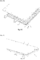
- the heat shield 10 may consist of a layer of material with low thermal conductivity, preferably an insulating material, attached with intimate application to the second face 6" of the surface element 6 with high thermal conductivity, either as a part separated secured by mechanical fixing, by gluing or by tightening ( figures 6 to 9 ), or as a locally overmolded layer ( figure 5 ).
- part 10 is preferentially premounted in the second part 7 or the bottom of the case 3' and in the second case the layer 10 is preferentially overmoulded on the surface element 6.
- the element 10 can also result from a particular local treatment of the surface element 6 itself.
- this layer or part 10 are adapted to the local geometry of the region, and its possibly variable thickness, depending on the results of thermal maps of the type mentioned above.
- said layer or piece 10 may also extend only over part of the surface of the face 6 "impacted excessively, for example frontally or at least with a significant angle of incidence, by the flow of fluid liquid FC, depending on the degree of reduction of the desired local cooling effect.
- an element 10 locally degrading the heat exchange between the said fluid liquid FC and the first face 6' of the surface element 6 in contact with the cells 2, is present in the region adjoining the supply inlet 9, at least at the level of an area of the element 6 capable of to be impacted frontally by the flow of liquid heat transfer fluid (FC), and advantageously also in at least one other region of said surface element 6 likely to be impacted substantially frontally by the flow of liquid heat transfer fluid FC. It is at these locations, and at those without cells 2 in contact, that the effect of an element 10 proves to be the most effective and necessary to solve the problem posed by the invention.
- FC liquid heat transfer fluid
- the element or each element 10 locally degrading the heat exchange between said liquid fluid FC and the first face 6′ of the surface element 6 extends at least partially in the channel portions 8′′ forming said at least one path or circulation network 8′, at least close to the supply inlet 9.
- These channel portions 8′′ can for example form part of or constitute the beginnings of secondary ramifications of a conduit or supply collector channel of several 8' channel portions.
- the or each added part 10 forming a thermal screen is secured by clamping by being sandwiched between the surface element 6 with high thermal conductivity and either the other complementary surface element 7, or the bottom wall 3' of the box 3 or a part of the latter (cf. figures 6 to 8 ).
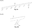
- the or each added part 10 forming a heat shield can comprise means 10' for centering and/or indexing during assembly, for example at least one molded or added centering (cf. figures 6A , 9A and 9B ).
- the or each insert 10 forming a heat shield can advantageously have a comb or rake shape.
- a high thermal conductivity, and more generally a good thermal transfer between the liquid fluid FC and the cells 2 is achieved by using a material for the surface element 6 which is intrinsically good thermal conductor (metal plate) and used in low thickness, in relation to a maximum contact surface and an optimized quality of contact between the surface element 6 and the cells 2, where appropriate of the module 2' concerned.
- a material for the surface element 6 which is intrinsically good thermal conductor (metal plate) and used in low thickness, in relation to a maximum contact surface and an optimized quality of contact between the surface element 6 and the cells 2, where appropriate of the module 2' concerned.
- the low conductivity of the thermal screen 10 can be achieved by using a material that is weakly thermally conductive, or even insulating. thermally, in combination with a relatively large thickness of this screen.
- high thermal conductivity ⁇ herein means values of ⁇ such that ⁇ > 50 Wm -1 .K -1 , preferably ⁇ > 100 Wm -1 .K -1 and by low thermal conductivity ⁇ , values ⁇ such that ⁇ 1 Wm -1 .K -1 , preferably ⁇ ⁇ 0.5 Wm -1 .K -1 .
- the material with good thermal conductivity has a conductivity between 100 W/m/K and 300 W/m/K, typically 200 W/m/K like aluminum.
- the low thermal conductivity material has a conductivity between 0.05 W/m/K and 0.5 W/m/K, typically 0.2 W/m/K like plastic type PP GF30.
- the invention also relates to a method of manufacturing a casing 3 for a battery unit 1 as described above and comprising a bottom region 4 on which the cells 2 of the battery rest and which comprises at least one, preferably several heat exchange zone(s) 5 between said cells 2 and the liquid heat transfer fluid (FC), said or each zone 5 comprising a surface element 6 with high thermal conductivity, preferably metallic, which is in contact on a first face 6' with cells 2 and in contact on its second face 6" with the liquid heat transfer fluid (FC), and which delimits with another complementary surface element 7, or with the bottom wall 3' of the casing 3 or a part of the latter, a cooling plate 5′ with an interstitial circulation volume 8, advantageously integrating at least one circulation path or network 8′ formed by channel portions 8′′, and which comprises at least one input of a supply 9 and at least one discharge outlet 9' for liquid heat transfer fluid.
- FC liquid heat transfer fluid
- This method is characterized in that it consists in providing the surface element 6 in simultaneous contact with the liquid fluid (FC) and the cells 2, by joining or by integration, with at least one element 10 locally degrading the exchange between said liquid fluid (FC) and the first face 6' of the surface element 6 in contact with the cells 2, this at least in a region 11 of the surface element 6 at the level of which no cell 2 is in contact with said first face 6' and/or at the level of which the liquid fluid circulation flow (FC) is likely to come into contact at a significant angle of incidence, even frontally or perpendicularly, with the second face 6" .
- the establishment and/or operation of a such a document or file can be produced by a human operator or else, at least partially or entirely, by computer means, if necessary associated with automated or robotic devices.
- the configuration of the privileged heat exchange zones 5 and that of the circulation paths 8' can initially be optimized to limit as much as possible the use of said elements or treatments locally degrading the heat exchange.
Landscapes
- Engineering & Computer Science (AREA)
- Manufacturing & Machinery (AREA)
- Chemical & Material Sciences (AREA)
- Chemical Kinetics & Catalysis (AREA)
- Electrochemistry (AREA)
- General Chemical & Material Sciences (AREA)
- Secondary Cells (AREA)
Applications Claiming Priority (1)
| Application Number | Priority Date | Filing Date | Title |
|---|---|---|---|
| FR2105051A FR3122946B1 (fr) | 2021-05-12 | 2021-05-12 | Unité de batterie avec des moyens de contrôle ou de régulation de température intégrés |
Publications (2)
| Publication Number | Publication Date |
|---|---|
| EP4089794A2 true EP4089794A2 (de) | 2022-11-16 |
| EP4089794A3 EP4089794A3 (de) | 2022-11-30 |
Family
ID=78049277
Family Applications (1)
| Application Number | Title | Priority Date | Filing Date |
|---|---|---|---|
| EP22172437.0A Pending EP4089794A3 (de) | 2021-05-12 | 2022-05-10 | Batterieeinheit mit eingebauten mitteln zur temperaturkontrolle oder -regulierung |
Country Status (2)
| Country | Link |
|---|---|
| EP (1) | EP4089794A3 (de) |
| FR (1) | FR3122946B1 (de) |
Cited By (2)
| Publication number | Priority date | Publication date | Assignee | Title |
|---|---|---|---|---|
| CN118017090A (zh) * | 2024-04-10 | 2024-05-10 | 浙江易阳能源管理有限公司 | 一种阻燃液冷的新能源储能柜 |
| CN118281421A (zh) * | 2024-06-04 | 2024-07-02 | 山东科技大学 | 一种新能源船舶动力电池热管理系统 |
Citations (3)
| Publication number | Priority date | Publication date | Assignee | Title |
|---|---|---|---|---|
| US20170062884A1 (en) | 2015-09-02 | 2017-03-02 | General Electric Company | Energy storage device with reduced temperature variability between cells |
| WO2019197338A1 (fr) | 2018-04-10 | 2019-10-17 | Sogefi Air & Cooling | Unite de batterie integrant des zones d'echanges thermiques |
| WO2019243222A1 (fr) | 2018-06-21 | 2019-12-26 | Sogefi Air & Cooling | Ensemble modulable pour la circulation d'un fluide caloporteur dans une batterie pour vehicule automobile |
Family Cites Families (2)
| Publication number | Priority date | Publication date | Assignee | Title |
|---|---|---|---|---|
| EP2426775A4 (de) * | 2009-04-28 | 2013-10-30 | Hitachi Ltd | Elektrizitätsspeichermodul und elektrizitätsspeichervorrichtung damit |
| DE102012005871A1 (de) * | 2012-03-23 | 2013-09-26 | Valeo Klimasysteme Gmbh | Kühlvorrichtung für eine Fahrzeugbatterie sowie Fahrzeugbatterie mit Kühlvorrichtung |
-
2021
- 2021-05-12 FR FR2105051A patent/FR3122946B1/fr active Active
-
2022
- 2022-05-10 EP EP22172437.0A patent/EP4089794A3/de active Pending
Patent Citations (4)
| Publication number | Priority date | Publication date | Assignee | Title |
|---|---|---|---|---|
| US20170062884A1 (en) | 2015-09-02 | 2017-03-02 | General Electric Company | Energy storage device with reduced temperature variability between cells |
| WO2019197338A1 (fr) | 2018-04-10 | 2019-10-17 | Sogefi Air & Cooling | Unite de batterie integrant des zones d'echanges thermiques |
| WO2019197340A1 (fr) | 2018-04-10 | 2019-10-17 | Sogefi Air & Cooling | Unite de batterie avec des moyens de controle de temperature integres |
| WO2019243222A1 (fr) | 2018-06-21 | 2019-12-26 | Sogefi Air & Cooling | Ensemble modulable pour la circulation d'un fluide caloporteur dans une batterie pour vehicule automobile |
Cited By (2)
| Publication number | Priority date | Publication date | Assignee | Title |
|---|---|---|---|---|
| CN118017090A (zh) * | 2024-04-10 | 2024-05-10 | 浙江易阳能源管理有限公司 | 一种阻燃液冷的新能源储能柜 |
| CN118281421A (zh) * | 2024-06-04 | 2024-07-02 | 山东科技大学 | 一种新能源船舶动力电池热管理系统 |
Also Published As
| Publication number | Publication date |
|---|---|
| FR3122946B1 (fr) | 2023-07-21 |
| FR3122946A1 (fr) | 2022-11-18 |
| EP4089794A3 (de) | 2022-11-30 |
Similar Documents
| Publication | Publication Date | Title |
|---|---|---|
| EP3776686B1 (de) | Batterieeinheit mit integrierten wärmetauschzonen | |
| EP3776715B1 (de) | Batterieeinheit mit gehäuseintegrierter temperaturregelung | |
| EP3014676B1 (de) | Streifen aus elektrochemischen zellen zur herstellung eines batteriemoduls für ein elektro- oder hybridfahrzeug und verfahren zur herstellung von solch einem modul | |
| EP4005008B1 (de) | Batteriekühlmodul und vorrichtung sowie entsprechende batterie | |
| EP4121711B1 (de) | Vorrichtung zur thermischen regelung mindestens eines elektronischen bauteils | |
| WO2018104505A1 (fr) | Dispositif de stockage d'énergie électrique pour véhicule automobile et pièce rapportée formant une partie du boîtier d'un tel dispositif de stockage d'énergie | |
| WO2019069020A1 (fr) | Boîtier de protection d'un pack batterie intégrant des canaux de circulation d'un fluide caloporteur | |
| FR3122946A1 (fr) | Unité de batterie avec des moyens de contrôle ou de régulation de température intégrés | |
| EP3925018B1 (de) | Batterieeinheit und fahrzeug mit mindestens einer solchen batterieeinheit ausgestattet | |
| FR3061766A1 (fr) | Dispositif d'echange thermique, notamment pour la regulation thermique d'une batterie d'un vehicule automobile | |
| WO2018167382A1 (fr) | Echangeur thermique et dispositif de régulation thermique d'au moins un élément de stockage d'énergie électrique | |
| EP4595148A1 (de) | Vorrichtung zum beabstanden von batteriezellen eines fahrzeugbatteriepacks | |
| WO2018127641A1 (fr) | Echangeur thermique à deux rangées de tubes pour la régulation thermique d'une batterie d'un véhicule automobile | |
| WO2016156365A1 (fr) | Module de batterie, notamment pour véhicule automobile, et échangeur thermique pour module de batterie correspondant | |
| EP3676904A1 (de) | Schutzgehäuse eines batteriepacks mit kanälen zum transport einer wärmeübertragungsflüssigkeit | |
| EP3811432B1 (de) | Gehause mit einer modularen anordnung zur zirkulation eines wärmeübertragungsfluids in einer kraftfahrzeugbatterie | |
| FR3056829A1 (fr) | Dispositif de regulation thermique de batterie | |
| WO2019234351A1 (fr) | Dispositif de regulation thermique de cellules de stockage d'energie electrique d'un pack-batterie de grande surface | |
| FR3147431A1 (fr) | Module de batterie et procédé de fabrication associé | |
| WO2021053277A1 (fr) | Plaque d'echange thermique d'une batterie | |
| FR3129778A1 (fr) | Véhicule automobile comprenant un dispositif de refroidissement d’au moins un accumulateur électrique | |
| WO2021048499A1 (fr) | Dispositif de gestion thermique pour composant électrique et système comprenant un tel dispositif | |
| WO2016135155A1 (fr) | Dispositif thermo électrique notamment destiné à générer un courant électrique dans un véhicule automobile | |
| FR3124322A1 (fr) | Système électronique comprenant au moins un composant électrique et/ou électronique et un dispositif de régulation thermique. |
Legal Events
| Date | Code | Title | Description |
|---|---|---|---|
| PUAI | Public reference made under article 153(3) epc to a published international application that has entered the european phase |
Free format text: ORIGINAL CODE: 0009012 |
|
| STAA | Information on the status of an ep patent application or granted ep patent |
Free format text: STATUS: THE APPLICATION HAS BEEN PUBLISHED |
|
| PUAL | Search report despatched |
Free format text: ORIGINAL CODE: 0009013 |
|
| AK | Designated contracting states |
Kind code of ref document: A2 Designated state(s): AL AT BE BG CH CY CZ DE DK EE ES FI FR GB GR HR HU IE IS IT LI LT LU LV MC MK MT NL NO PL PT RO RS SE SI SK SM TR |
|
| AK | Designated contracting states |
Kind code of ref document: A3 Designated state(s): AL AT BE BG CH CY CZ DE DK EE ES FI FR GB GR HR HU IE IS IT LI LT LU LV MC MK MT NL NO PL PT RO RS SE SI SK SM TR |
|
| RIC1 | Information provided on ipc code assigned before grant |
Ipc: H01M 10/658 20140101ALI20221027BHEP Ipc: H01M 10/6556 20140101ALI20221027BHEP Ipc: H01M 10/653 20140101ALI20221027BHEP Ipc: H01M 10/625 20140101ALI20221027BHEP Ipc: H01M 10/617 20140101ALI20221027BHEP Ipc: H01M 10/613 20140101AFI20221027BHEP |
|
| STAA | Information on the status of an ep patent application or granted ep patent |
Free format text: STATUS: REQUEST FOR EXAMINATION WAS MADE |
|
| 17P | Request for examination filed |
Effective date: 20230529 |
|
| RBV | Designated contracting states (corrected) |
Designated state(s): AL AT BE BG CH CY CZ DE DK EE ES FI FR GB GR HR HU IE IS IT LI LT LU LV MC MK MT NL NO PL PT RO RS SE SI SK SM TR |
|
| P01 | Opt-out of the competence of the unified patent court (upc) registered |
Effective date: 20230620 |