EP4089833B1 - Antennenanordnung für einen am handgelenk getragenen trainingsrechner - Google Patents
Antennenanordnung für einen am handgelenk getragenen trainingsrechner Download PDFInfo
- Publication number
- EP4089833B1 EP4089833B1 EP21173806.7A EP21173806A EP4089833B1 EP 4089833 B1 EP4089833 B1 EP 4089833B1 EP 21173806 A EP21173806 A EP 21173806A EP 4089833 B1 EP4089833 B1 EP 4089833B1
- Authority
- EP
- European Patent Office
- Prior art keywords
- casing
- wrist
- antenna
- display lens
- electrically conductive
- Prior art date
- Legal status (The legal status is an assumption and is not a legal conclusion. Google has not performed a legal analysis and makes no representation as to the accuracy of the status listed.)
- Active
Links
Images




Classifications
-
- A—HUMAN NECESSITIES
- A61—MEDICAL OR VETERINARY SCIENCE; HYGIENE
- A61B—DIAGNOSIS; SURGERY; IDENTIFICATION
- A61B5/00—Measuring for diagnostic purposes; Identification of persons
- A61B5/68—Arrangements of detecting, measuring or recording means, e.g. sensors, in relation to patient
- A61B5/6801—Arrangements of detecting, measuring or recording means, e.g. sensors, in relation to patient specially adapted to be attached to or worn on the body surface
- A61B5/6802—Sensor mounted on worn items
- A61B5/681—Wristwatch-type devices
-
- H—ELECTRICITY
- H01—ELECTRIC ELEMENTS
- H01Q—ANTENNAS, i.e. RADIO AERIALS
- H01Q1/00—Details of, or arrangements associated with, antennas
- H01Q1/27—Adaptation for use in or on movable bodies
- H01Q1/273—Adaptation for carrying or wearing by persons or animals
-
- A—HUMAN NECESSITIES
- A61—MEDICAL OR VETERINARY SCIENCE; HYGIENE
- A61B—DIAGNOSIS; SURGERY; IDENTIFICATION
- A61B5/00—Measuring for diagnostic purposes; Identification of persons
- A61B5/0002—Remote monitoring of patients using telemetry, e.g. transmission of vital signals via a communication network
-
- A—HUMAN NECESSITIES
- A61—MEDICAL OR VETERINARY SCIENCE; HYGIENE
- A61B—DIAGNOSIS; SURGERY; IDENTIFICATION
- A61B5/00—Measuring for diagnostic purposes; Identification of persons
- A61B5/02—Detecting, measuring or recording for evaluating the cardiovascular system, e.g. pulse, heart rate, blood pressure or blood flow
- A61B5/0205—Simultaneously evaluating both cardiovascular conditions and different types of body conditions, e.g. heart and respiratory condition
- A61B5/02055—Simultaneously evaluating both cardiovascular condition and temperature
-
- A—HUMAN NECESSITIES
- A61—MEDICAL OR VETERINARY SCIENCE; HYGIENE
- A61B—DIAGNOSIS; SURGERY; IDENTIFICATION
- A61B5/00—Measuring for diagnostic purposes; Identification of persons
- A61B5/02—Detecting, measuring or recording for evaluating the cardiovascular system, e.g. pulse, heart rate, blood pressure or blood flow
- A61B5/024—Measuring pulse rate or heart rate
- A61B5/02416—Measuring pulse rate or heart rate using photoplethysmograph signals, e.g. generated by infrared radiation
-
- A—HUMAN NECESSITIES
- A61—MEDICAL OR VETERINARY SCIENCE; HYGIENE
- A61B—DIAGNOSIS; SURGERY; IDENTIFICATION
- A61B5/00—Measuring for diagnostic purposes; Identification of persons
- A61B5/02—Detecting, measuring or recording for evaluating the cardiovascular system, e.g. pulse, heart rate, blood pressure or blood flow
- A61B5/024—Measuring pulse rate or heart rate
- A61B5/02438—Measuring pulse rate or heart rate with portable devices, e.g. worn by the patient
-
- A—HUMAN NECESSITIES
- A61—MEDICAL OR VETERINARY SCIENCE; HYGIENE
- A61B—DIAGNOSIS; SURGERY; IDENTIFICATION
- A61B5/00—Measuring for diagnostic purposes; Identification of persons
- A61B5/05—Detecting, measuring or recording for diagnosis by means of electric currents or magnetic fields; Measuring using microwaves or radio waves
- A61B5/053—Measuring electrical impedance or conductance of a portion of the body
-
- A—HUMAN NECESSITIES
- A61—MEDICAL OR VETERINARY SCIENCE; HYGIENE
- A61B—DIAGNOSIS; SURGERY; IDENTIFICATION
- A61B5/00—Measuring for diagnostic purposes; Identification of persons
- A61B5/103—Measuring devices for testing the shape, pattern, colour, size or movement of the body or parts thereof, for diagnostic purposes
- A61B5/11—Measuring movement of the entire body or parts thereof, e.g. head or hand tremor or mobility of a limb
- A61B5/1112—Global tracking of patients, e.g. by using GPS
-
- A—HUMAN NECESSITIES
- A61—MEDICAL OR VETERINARY SCIENCE; HYGIENE
- A61B—DIAGNOSIS; SURGERY; IDENTIFICATION
- A61B5/00—Measuring for diagnostic purposes; Identification of persons
- A61B5/145—Measuring characteristics of blood in vivo, e.g. gas concentration or pH-value ; Measuring characteristics of body fluids or tissues, e.g. interstitial fluid or cerebral tissue
- A61B5/14542—Measuring characteristics of blood in vivo, e.g. gas concentration or pH-value ; Measuring characteristics of body fluids or tissues, e.g. interstitial fluid or cerebral tissue for measuring blood gases
-
- A—HUMAN NECESSITIES
- A61—MEDICAL OR VETERINARY SCIENCE; HYGIENE
- A61B—DIAGNOSIS; SURGERY; IDENTIFICATION
- A61B5/00—Measuring for diagnostic purposes; Identification of persons
- A61B5/24—Detecting, measuring or recording bioelectric or biomagnetic signals of the body or parts thereof
- A61B5/316—Modalities, i.e. specific diagnostic methods
- A61B5/318—Heart-related electrical modalities, e.g. electrocardiography [ECG]
-
- A—HUMAN NECESSITIES
- A61—MEDICAL OR VETERINARY SCIENCE; HYGIENE
- A61B—DIAGNOSIS; SURGERY; IDENTIFICATION
- A61B5/00—Measuring for diagnostic purposes; Identification of persons
- A61B5/48—Other medical applications
- A61B5/4869—Determining body composition
-
- G—PHYSICS
- G06—COMPUTING OR CALCULATING; COUNTING
- G06F—ELECTRIC DIGITAL DATA PROCESSING
- G06F1/00—Details not covered by groups G06F3/00 - G06F13/00 and G06F21/00
- G06F1/16—Constructional details or arrangements
- G06F1/1613—Constructional details or arrangements for portable computers
- G06F1/163—Wearable computers, e.g. on a belt
-
- H—ELECTRICITY
- H01—ELECTRIC ELEMENTS
- H01Q—ANTENNAS, i.e. RADIO AERIALS
- H01Q5/00—Arrangements for simultaneous operation of antennas on two or more different wavebands, e.g. dual-band or multi-band arrangements
- H01Q5/30—Arrangements for providing operation on different wavebands
- H01Q5/378—Combination of fed elements with parasitic elements
-
- H—ELECTRICITY
- H01—ELECTRIC ELEMENTS
- H01Q—ANTENNAS, i.e. RADIO AERIALS
- H01Q7/00—Loop antennas with a substantially uniform current distribution around the loop and having a directional radiation pattern in a plane perpendicular to the plane of the loop
Definitions
- Various embodiments relate to antenna arrangements in a wrist-worn training computer.
- Wrist devices such as wrist-worn training computers
- Wrist devices may be equipped with a large number of features, such as various sensors used to measure physiological parameters, features for wireless communication, and global or local positioning features.
- Especially antenna arrangements may be large and add to the weight of the wrist device.
- a training computer with good performance may be large and heavy due to the different components required for each feature.
- Such a device may be uncomfortable to wear.
- Wrist devices may also be exposed to harsh conditions, especially outdoors. Additional components intended for protecting the device are often included in such devices, further increasing their size and weight. Solutions that provide good performance while allowing a reasonable size and weight are therefore desirable.
- WO2021/071667A1 discloses the electronic device including a housing, a display cover, and a modular component configured to provide a seal between the housing to the display cover.
- the modular component is configured to be attached to the housing.
- the modular component includes a first surface configured to be attached to the display cover.
- the modular component includes a channel extending along the first surface, where the channel is configured to hold a liquid adhesive that bonds with the display cover.
- the modular component further includes a radial protrusion disposed on the first surface, the radial protrusion is configured to be in contact with the display cover when the display cover is attached to the housing and to prevent the liquid adhesive from moving out of the channel.
- US2020/243952A1 discloses an antenna which is provided for a wearable personal computing device, such as a smartwatch.
- the antenna integrates with other components of the wearable device, such as a second antenna.
- the first antenna may be a coupled loop antenna in proximity to a second antenna that may be a monopole antenna, without causing interference between the two antennas.
- the first antenna shares a common ground with the second antenna.
- JP2019153979A discloses a technique for mitigating the directivity of an antenna.
- the antenna comprises a first antenna including a first electrode plate, a second electrode plate, and a first short circuit part that short-circuits between the first electrode plate and second electrode plate; and a second antenna including an annular conductive member that is electrically connected to the first antenna.
- CN111916887A discloses wearable equipment and an antenna processing method thereof. According to the wearable equipment disclosed by the invention, an antenna structure design of all-metal shell equipment can be realized, and the wearable equipment has better equipment structure strength and appearance integration.
- Air and creep distances are thus implemented in particular in a simple manner in that the cross-section of the sliding cover is substantially designed and/or profiled such that, when the sliding cover is arranged in the input region of the axial groove, the region of the insulation element adjoining the sliding cover is guided substantially in the direction of the center region of the sliding cover at an angle and correspondingly aligned.
- US20190051975A1 discloses a portable electronic apparatus including a case, a solar cell disposed in the case, a GPS antenna as an antenna section disposed in the case, including a base as a nonconductive member and a conductive body disposed on a surface of the nonconductive member, and adapted to receive a positioning satellite signal, and a circuit board disposed in the case, and electrically connected to the solar cell and the antenna section, and the antenna section overlaps the solar cell in a planar view viewed from a normal direction of light receiving surfaces of the solar cell.
- the present invention is concerned with a wrist device, specifically a wrist-worn training computer, comprising one or more biosensors; a casing; a display lens positioned against the casing to form an interface between the display lens and the casing, and to enclose together with the casing an enclosed space between the casing and the display lens; a first part of an antenna of a satellite navigation receiver disposed within the enclosed space; a gasket positioned along the interface between the display lens and the casing to seal the enclosed space, wherein the gasket comprises electrically conductive material that forms a second part of the antenna.
- the wrist device has an antenna of a satellite navigation receiver.
- the antenna may be configured to receive global navigation satellite system (GNSS) signals.
- GNSS global navigation satellite system
- the antenna may thus be used to communicate with GNSS satellites and to carry out positioning, navigation, and tracking of the location of the wrist device.
- the ability and performance of the wrist device in carrying out the aforementioned tasks is dependent on the radiation characteristics of the satellite navigation receiver antenna.
- RHCP right hand circularly polarized
- LHCP left hand circularly polarized
- the wrist device further comprises a gasket positioned along the interface between the display lens and the casing.
- the gasket serves two purposes: the first purpose of the gasket is to seal the interface between the display lens and the casing, therefore also sealing the enclosed space between the display lens and the casing.
- the second purpose of the gasket is to operate as the second part of the satellite navigation receiver antenna, further improving its radiation characteristics.
- the second purpose is achieved by electrically conductive material comprised within the gasket.
- the electrically conductive material forming the second part of the antenna coupled with the first part of the antenna form the satellite navigation receiver antenna.
- the antenna has improved radiation characteristics and RHCP gain when compared to the first part of the antenna alone. In particular with the plastic casing, the improved radiation characteristics can be gained without increasing the size or dimensions of the first part of the antenna inside the casing.
- the casing or chassis may provide a frame or a body of the wrist device.
- the casing may be used to protect internal components of the wrist device by shielding them from external factors, such as moisture or spillage.
- the casing may be made of an electrically insulating material.
- the casing is a plastic casing, which also has the advantage of being light-weight.
- the display lens is positioned against the casing, forming an interface between the display lens and the casing.
- the display lens has an external surface facing away from the casing, and an internal surface facing towards the casing.
- the display lens and the casing further enclose together an enclosed space between the casing and the display lens.
- the display lens may also be used to protect internal components of the wrist device.
- the display lens may be made of transparent material such as glass or a transparent plastics material.
- the enclosed space between the display lens and the casing is sealed with the gasket to protect sensitive electronic and non-electronic components disposed therein.
- Humidity, moisture, fluid spills as well as dust and other particles may damage the sensitive components and potentially render the device unusable.
- a wrist device used for sports may also be submerged during certain activities, such as swimming.
- a waterproof seal to protect the sensitive components may therefore be required and is achieved by the gasket.
- the wrist device may be considered a smart watch or a sports watch.
- the wrist device may be capable of measuring and/or monitoring physical and/or physiological parameters, such as a temperature or a heart rate of the wearer of the wrist device.
- the biosensors may be configured to sense motion, acceleration, temperature, electrocardiogram (ECG), photoplethysmogram (PPG), or electrical impedance, for example. These capabilities may be achieved by a variety of biosensors.
- the biosensors comprise at least one of: an optical heart rate sensor, an oxygen saturation sensor, a temperature sensor, an electrocardiography sensor, a bioimpedance sensor, a body composition sensor.
- FIG. 1 A side view of an embodiment of the wrist device is shown in Figure 1 .
- the wrist device 100 comprises the casing 104 and the display lens 106, and the interface between the casing and the display lens is sealed by the gasket 110.
- the gasket is positioned against the internal surface of the display lens.
- the first part of the antenna 108 is enclosed in the space between the display lens and the casing.
- Biosensors 102 such as an optical heart rate sensor are also illustrated on the wrist-facing surface of the wrist device.
- Straps 114, 116 of a wristband for attaching the watch to the wrist of its user may extend from opposite sides of the casing.
- a bezel 112 is also included in the embodiment of Figure 1 .
- the bezel may be made of the same material as the casing, or it may be made of a different material.
- the bezel may be made of an electrically conductive material or an electrically non-conductive material. In the case of an electrically conductive bezel, the bezel may form a third part of the antenna.
- the bezel may be an integral part of the casing, or it may be a separate part attached to the rest of the casing.
- the bezel may surround the display lens, and it may extend past the external surface of the display lens, so that the display lens may appear sunken, as illustrated in Figure 1 .
- the bezel may also extend over the display lens to cover a part of the external surface of the display lens.
- the bezel may be used to secure the display lens in its place against the casing.
- the interface between the display lens and the casing may be between the display lens and the bezel, or between the display lens and both the bezel and another part of the casing.
- Figure 3 illustrates an embodiment with a similar appearance to that of Figure 2 , with the addition of a bezel 112.
- the sealing gasket may be entirely or partially concealed by the display lens, the casing and/or the bezel, and is not visible in Figure 3 .
- Embodiments with different configurations and relative positions of the gasket, the display lens, and the bezel are illustrated in Figures 4-6 .
- Each one of these figures represents an alternative embodiment of the gasket, the display lens, and the bezel, that may correspond to the cross-section A-A of the wrist device illustrated in Figure 3 .
- the different configurations are discussed in further detail below.
- the embodiment of Figure 4 comprises a bezel 112 that extends over the external surface of the display lens.
- the bezel is shown to be touching the external surface of the display lens, however, it is not necessary for the bezel to be in contact with the external surface of the display lens, and a gap between the two is allowed. However, if the bezel is touching or in contact with the display lens, it may be used to secure the display lens in its place. Moreover, dirt build-up may occur in a gap between the bezel and the display lens.
- the gasket 400 is positioned between the internal surface of the display lens and the casing. The gasket may also extend further along the casing past the edge of the display lens, between the bezel and the casing.
- Figure 5 illustrates an embodiment wherein the gasket 500 is arranged against the edge of the display lens, in a similar manner as in the embodiment of Figure 2 .
- the embodiment also includes a bezel 112 extending over the external surface of the display lens.
- the gasket 500 is between the edge of the display lens and the bezel of the casing.
- the gasket is also surrounded by the casing and the bezel on its top and bottom sides, as shown in Figure 5 .
- the gasket has an L-shaped cross-section. As illustrated in Figure 6A , the gasket 600 may be against both the internal surface and the edge of the display lens. In Figure 6 , the gasket is also against both the casing and the bezel of the wrist device. In an alternative embodiment illustrated in Figure 6B , the gasket 602 with an L-shaped cross-section may be against both the external surface and the edge of the display lens. In a yet alternative embodiment illustrated in Figure 6C , the gasket 604 has a U-shaped cross-section, allowing for it to be against the display lens along the edge, the internal surface, and the external surface of the display lens.
- first part of the antenna the second part of the antenna, i.e. the gasket
- their relative positions may affect the radiation characteristics of the antenna.
- the first part of the antenna and the second part of the antenna are capacitively coupled. Capacitive coupling may be achieved by the proximity of the first part and the second part of the antenna.
- the first part of the antenna and the second part of the antenna may be separated by a distance of 2-3 millimetres (mm), or by a distance smaller than 2 mm, for example. Close proximity, i.e. a small distance between the first part of the antenna and the second part of the antenna also allows for a smaller size of the wrist device.
- the electrically conductive material forms a closed loop.
- the gasket itself may also form a closed loop along the interface between the display lens and the casing to seal the interface effectively.
- the electrically conductive material may extend along the gasket to form a closed loop. The closed loop formed by the electrically conductive material forming the second part of the antenna may improve the radiation characteristics of the antenna.
- the electrically conductive material forms an annular loop.
- the gasket itself may also have an annular shape, such as in the embodiment of Figure 2 .
- the annular loop may also improve the radiation characteristics of the antenna.
- the electrically conductive material forms a penannular shape.
- the electrically conductive material may form an almost complete annulus with a break.
- the electrically conductive material forms a semi-annular shape. In both embodiments, the shape of the conductive material may improve the radiation characteristics of the antenna.
- the electrically conductive material extends in a first plane parallel to the display lens and turns to a second plane perpendicular to the display lens.
- the conductive material may extend in the first plane along the internal surface of the display lens, or around the display lens along the edge of the display lens, for example.
- the conductive material may also extend in the second plane perpendicular to the display lens, such as transversely along the edge of the display lens, such as from the level of the internal surface to the level of the external surface of the display lens.
- An example of this embodiment is the L-shaped gasket 600 of Figure 6 .
- the gasket may also serve a third purpose in addition to sealing interface between the display lens and the casing and forming the second part of the antenna.
- the gasket comprises a plurality of layers comprising an adhesive layer and an electrically conductive layer made of the electrically conductive material that forms the second part of the antenna.
- the gasket has a multi-layered structure. Some layers of the multi-layered structure may be similar, or all layers of the multi-layered structure may be different. Layers with different properties may perform different functions of the gasket.
- the adhesive layer may be used to attach the gasket to the display lens and/or the casing, and/or to attach the display lens to the casing. Other means for attaching the display lens to the casing, such as snap-fit joints, may also be used.
- the display lens may also be attached to a bezel of the casing, and it may be secured between the bezel and the casing, as illustrated in Figures 4-6 .
- the adhesive layer may join the gasket to the display lens and/or the casing, and the adhesive layer may prevent movement of the joined parts relative to each other, ensuring that the gasket is not displaced, and the seal is not compromised.
- the electrically conductive material forming the second part of the antenna may be located within a layer of the multi-layered gasket.
- the conductive layer may be very thin and have a thickness of less than 0.1 millimetres (mm), e.g. 0.05 mm.
- the electrically conductive material may be copper or aluminium, for example.
- the conductive layer may be made of metal foil, such as copper or aluminium foil.
- the gasket comprises two or more electrically conductive layers made of the electrically conductive material, that together form the second part of the antenna.
- the multi-layered gasket may also comprise other, different kinds of layers in addition to the electrically conductive layer(s).
- the gasket comprises a first adhesive layer and a second adhesive layer, wherein the conductive layer is between the first adhesive layer and the second adhesive layer.
- the first adhesive layer and the second adhesive layer may be made of electrically insulating materials to electrically insulate the conductive layer that is sandwiched between the adhesive layers.
- the first and second adhesive layers may be made of adhesive tape.
- the adhesive tape may be two-sided, i.e. having an adhesive surface on both sides of the tape.
- the first adhesive layer made of two-sided adhesive tape may adhere to a first side of the electrically conductive material, such as thin metal foil, and the second adhesive layer made of two-sided adhesive tape may adhere to a second side of the electrically conductive material, leaving the other side of both adhesive tapes exposed for further attachment.
- the resulting multi-layered gasket may still be very thin, with a thickness of 0.45 mm, for example.
- a multi-layered gasket structure 700 with a plurality of layers is illustrated in Figure 7 .
- the structure includes a liner 702 and a carrier 710.
- the liner and the carrier cover the otherwise exposed adhesive surfaces of the first and second adhesive layers.
- the liner is also used to align the gasket during assembly of the wrist device.
- the liner and the carrier are removed from the gasket during the assembly of the wrist device.
- the gasket is positioned so that the first adhesive layer is against the display lens to adhere the gasket to the display lens, and the second adhesive layer is against the casing to adhere the gasket to the casing, so that the display lens adheres to the casing via the gasket.
- the carrier layer of the gasket may be removed, exposing the adhesive surface on the second adhesive layer.
- the exposed adhesive surface on the second adhesive layer of the gasket may be placed against the casing, and the adhesive of the second adhesive layer attaches the gasket to the casing.
- the liner layer of the gasket may then be removed, exposing the adhesive surface on the first adhesive layer.
- the display lens may be placed against the first adhesive layer, and the adhesive of the first adhesive layer attaches the gasket to the display lens. The display lens is therefore attached to the casing via the gasket.
- the gasket in the present invention has a uniform structure.
- the gasket has a uniform structure made of the electrically conductive material.
- the uniform structure may be moulded to any desired shape of the gasket, including the annular shape described earlier.
- the electrically conductive material is an electrically conductive paste having electrically conductive particles dispersed in a medium. Electrical conductivity of the paste is achieved by the conductive particles.
- the conductive particles may be copper, silver, or nickel particles, for example.
- the paste may be applied to the interface between the display lens and the casing during the assembly of the wrist device.
- the electrically conductive paste is an electrically conductive adhesive that adheres the display lens to the casing.
- the paste may comprise an adhesive component, such as a silicone or epoxy adhesive, and the conductive particles are dispersed within the adhesive component.
- the gasket made of the electrically conductive adhesive may be used to attach the casing to the display lens.
- the conductive adhesive may be applied to the casing and/or the display lens, and the casing and the display lens are placed against each other.
- the conductive adhesive forms a seal and joins the casing and the display lens together.
- the conductive adhesive may also be applied to the bezel of the casing to join the bezel to the display lens and/or the casing.
- the first part of the antenna is a folded dipole type of antenna with a gamma match, or a gamma matched dipole antenna with or without ground point impedance tuning, referred to as 'folded dipole antenna' herein.
- An embodiment of the folded dipole antenna is illustrated in Figure 8 .
- the folded dipole antenna 800 comprises: an elongated conductive element 802; a feed contact 804 coupled to the conductive element at a feed point 806; a first ground contact 808 coupled to the conductive element at a first ground point 810; and a second ground contact 812 coupled to the conductive element at a second ground point 814.
- the radiation characteristics of the folded dipole antenna may depend on the locations of the feed point, the first ground point and the second ground point, and the distance between the ends of the folded dipole antenna. The radiation characteristics may also depend on electrical components used to couple the ground contacts to a ground plane. A desired radiation pattern and polarization of the folded dipole antenna may thus be achieved by adjusting these factors.
- the folded dipole antenna may be configured to one or more desired frequency bands, such as: GPS L5 at 1176.45 MHz; GNSS L1 bands including Galileo, BeiDou, GLONASS, GPS, at frequencies of 1561-1609 MHz; and Bluetooth at frequencies of 2400-2483.5 MHz.
- the feed point is between the first ground point and the second ground point and at certain distances from the ground points, respectively.
- the feed point may be positioned in a location along the conductive element that is between the locations of the first and second ground point.
- the first ground point may be between the feed point and the second ground point, or the second ground point may be between the feed point and the first ground point. Radiation characteristics of the folded dipole antenna may be modified by positioning of the feed point.
- the feed point is at a midpoint of the conductive element. In other words, the feed point is at an equal distance from both ends of the conductive element.
- the conductive element may be symmetrical about the feed point. The location of the feed point at the midpoint of the conductive element may also improve the radiation characteristics of the folded dipole antenna.
- the feed point is substantially in a midpoint between the ground points 810, 814.
- the first ground point is at a midpoint of the conductive element, i.e., at an equal distance from both ends of the conductive element.
- the feed point is the only feed point of the folded dipole antenna. Only one feed point allows for a simpler design of the folded dipole antenna and it may also affect its radiation characteristics.
- the folded dipole antenna comprises a first capacitor to couple the first ground contact to the ground plane, and a second capacitor to couple the second ground contact to the ground plane.
- the capacitors may have the same values, or they may have different values.
- the values of the capacitors may be in a range of 0.1 to 2.0 picofarads (pF), for example.
- the first capacitor has a value of 0.6 pF
- the second capacitor has a value of 0.3 pF.
- the first capacitor has a value of 1.4 pF
- the second capacitor has a value of 0.9 pF.
- the components used to couple the ground contacts to the ground plane may also include inductors, conductors, diodes, and/or resistors.
- the folded dipole antenna comprises a first inductor to couple the first ground contact to the ground plane, and a second inductor to couple the second ground contact to the ground plane.
- the inductors may have the same values, or they may have different values, and their values may affect the radiation characteristics of the folded dipole antenna.
- the folded dipole antenna comprises at least one of: an inductor and a capacitor, to couple the first ground contact or the second ground contact to the ground plane.
- the folded dipole antenna further comprises a conductor to couple the first ground contact or the second ground contact to the ground plane.
- the folded dipole antenna comprises an inductor and a capacitor to couple the first and second ground contact to the ground plane.
- the folded dipole antenna comprises a diode, specifically an electrostatic discharge (ESD) diode, to couple the first or the second ground contact to the ground plane.
- ESD electrostatic discharge
- the folded dipole antenna comprises an impedance matching circuit coupled to the feed contact. Impedance matching may be done to maximize power transfer and/or minimize signal reflection.
- a first loop may be formed along the folded dipole antenna via the feed contact and the grounded first ground contact.
- a second loop may be formed along the folded dipole antenna via the feed contact and the grounded second ground contact.
- the shape of the conductive element of the folded dipole antenna may also have an effect on its radiation characteristics.
- the conductive element forms a penannular shape with a break 816 between the ends of the conductive element, as illustrated in Figure 8 .
- a penannular shape may be conveniently fitted to a wrist device, as the conductive element may extend along a wall of a cylindrical watch casing, specifically along the inner wall of the casing.
- the break may have a width of 1-4 mm, i.e. the ends of the conductive element may be separated by a distance of 1-4 mm, for example.
- the feed point is located opposite the break between the ends of the conductive element, the first ground point is located 1/12 th of a full revolution anticlockwise from the feed point, and the second ground point is located 1/12 th of a full revolution clockwise from the feed point.
- Figure 8 also approximately shows the above positions of the feed point, the first and second ground points, and the break.
- the folded dipole antenna according to the above embodiment may be configured to receive RHCP signals from navigational satellites.
- the radiation pattern of the above folded dipole antenna may be focused in directions between a direction 818 pointing 1/6 th of a full revolution clockwise of the break 816, and a perpendicular direction towards the viewer of Figure 8 .
- the folded dipole antenna may be positioned in the wrist device in a way that allows for directing the RHCP radiation pattern towards navigational satellites when the wrist device is worn on the wrist of its user.
- the positioning and orientation of the folded dipole antenna is now discussed with reference to an imaginary clock face of the wrist device.
- Wrist devices such as wristwatches
- Wrist devices are often worn so that a display or a clock face of a wrist device is on the back side of the wrist, and the straps of the wristband extend across the palm side of the wrist.
- the clock face of an analog wristwatch is traditionally oriented so that when the wristwatch is worn on the left hand, the direction of 3 o'clock points towards the fingers, the direction of 6 o'clock is on the radial side of the wrist, the direction of 9 o'clock points towards the elbow, and the direction of 12 o'clock is on the ulnar side of the wrist.
- the direction of 3 o'clock points towards the elbow
- the direction of 6 o'clock is on the radial side of the wrist
- the direction of 9 o'clock points towards the fingers
- the direction of 12 o'clock is on the ulnar side of the wrist.
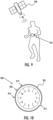
- a wrist device 902 When the user of a wrist device 902 is exercising, such as running or walking, their arms are often bent at the elbow so that the radial side of the wrist is pointing upwards or towards the sky, as shown in Figure 9 .
- the direction of 6 o'clock of a clock face of a wrist device is usually on the radial side of the wrist, irrespective of whether the wrist device is worn on the left hand or the right hand.
- the direction of 6 o'clock is therefore pointing towards the sky, and towards navigational satellites 900.
- the back side of the wrist may also be facing towards the sky.
- the display of the wrist device is often on the back side of the wrist, the display may therefore also be pointing towards the sky, and towards navigational satellites.
- the folded dipole antenna is positioned relative to an imaginary clock face of the wrist device so that the break between the open ends of the antenna is in a direction of 4 o'clock, the first ground point is in the direction of 9 o'clock, the feed point is in a direction of 10 o'clock, and the second ground point is in a direction of 11 o'clock.
- the positioning of the folded dipole antenna with respect to an imaginary clock face is illustrated in Figure 10 .
- the above positioning allows for directing the radiation pattern of the folded dipole antenna towards navigational satellites in the sky.
- the radiation pattern of the folded dipole antenna that was described earlier may now be described in relation to the wrist device: the radiation pattern may be focused in directions between the direction of 6 o'clock on the imaginary clock face of the wrist device, and a perpendicular direction away from the imaginary clock face, which corresponds to a perpendicular direction away from the display lens or screen of the wrist device.
- the clock face discussed above is an imaginary analog clock face.
- the wrist device may have a clock face similar to the imaginary clock face, or the wrist device may have a digital clock face as shown in Figure 11 , or the wrist device may not have a clock face at all.
- Figure 11 illustrates a wrist device 1100 in an orientation that may occur during an activity such as cycling, where the display is facing up towards the sky.
- a wrist device 1102 is also illustrated in an orientation that may occur while running or walking.
- the bottom of the digital clock face of wrist device 1102, corresponding to the direction of 6 o'clock in the imaginary analog clock face, is pointing towards the navigational satellite 900.
- Navigational signals from the satellite 900 are received from the direction of 6 o'clock of the imaginary clock face.
- the display of wrist device 1100 is pointing towards the navigational satellite 900, meaning that navigational signals from the satellite are received in a perpendicular direction away from the display screen.
- Both devices 1100 and 1102 are oriented in a way that directs the RHCP radiation pattern towards the navigational satellite 900.
- a conductive element 1200 is embedded in the inner wall of the casing 1202.
- a bezel 1204 and an electromagnetic shield 1206 are also shown.
- a feed contact 1300 is between a first ground contact 1302 and a second ground contact 1304.
- the ground contacts are coupled to a ground plane 1208.
- a break 1210 between the ends of the conductive element 1200 may be filled by the non-conductive casing extending into the break. The break may be approximately 2 mm wide, i.e. the ends of the conductive element may be separated by a distance of approximately 2 mm.
- the radiation pattern of the folded dipole antenna is often directed towards navigational satellites when the wrist device is in use. This is due to the advantageous positioning of the folded dipole antenna within the wrist device and allows for good reception of RHCP signals from navigational satellites.
- Figure 14 illustrates alternative embodiments of the folded dipole antenna 1400 wherein the conductive element 1402 is also penannular.
- the first ground point 1410 is located 1/6 th of a full revolution clockwise of the feed point 1406
- the second ground point 1414 is located opposite the feed point
- the break 1416 between the ends of the conductive element is located 1/4 th of a full revolution clockwise of the second ground point.
- the folded dipole antenna according to the above embodiment may be configured to receive RHCP signals from navigational satellites.
- the radiation pattern of the above folded dipole antenna may be focused in multiple directions ranging from an upwards direction 1418, to a perpendicular direction towards the viewer of Figure 14 , and to a downwards direction 1420, for example.
- the folded dipole antenna is positioned relative to an imaginary clock face of the wrist-worn training computer so that the break between the open ends of the antenna is in a direction of 2 o'clock, the feed point is in a direction of 5 o'clock, the first ground point is in the direction of 7 o'clock, and the second ground point is in a direction of 11 o'clock.
- the positioning of the folded dipole antenna with respect to an imaginary clock face is also illustrated in Figure 14 .
- the radiation pattern of the folded dipole antenna according to the above embodiment may be focused in multiple directions ranging from the direction of 12 o'clock on the imaginary clock face of the wrist-worn training computer, to a perpendicular direction away from the imaginary clock face, which corresponds to a perpendicular direction away from the display screen of the training computer, and to a direction of 6 o'clock on the imaginary clock face, for example.
- the radiation pattern may therefore be directed towards navigational satellites in multiple orientations of the wrist device, including the orientations shown in Figure 11 .
- a conductive element 1500 is embedded in the inner wall of the casing 1502.
- a bezel 1504 and a feed contact 1600 are also shown.
- a first ground contact 1506 and a second ground contact 1508 are coupled to a ground plane 1510.
- a break 1602 between the ends of the conductive element 1500 may be filled by the non-conductive casing extending into the break.
- the break may be approximately 3.7 mm wide, i.e. the ends of the conductive element may be separated by a distance of approximately 3.7 mm.
Landscapes
- Health & Medical Sciences (AREA)
- Life Sciences & Earth Sciences (AREA)
- Engineering & Computer Science (AREA)
- Physics & Mathematics (AREA)
- Animal Behavior & Ethology (AREA)
- Veterinary Medicine (AREA)
- Public Health (AREA)
- General Health & Medical Sciences (AREA)
- Surgery (AREA)
- Biophysics (AREA)
- Pathology (AREA)
- Biomedical Technology (AREA)
- Heart & Thoracic Surgery (AREA)
- Medical Informatics (AREA)
- Molecular Biology (AREA)
- Cardiology (AREA)
- Physiology (AREA)
- Computer Hardware Design (AREA)
- Theoretical Computer Science (AREA)
- General Physics & Mathematics (AREA)
- Radiology & Medical Imaging (AREA)
- Radar, Positioning & Navigation (AREA)
- Human Computer Interaction (AREA)
- Dentistry (AREA)
- Oral & Maxillofacial Surgery (AREA)
- Nuclear Medicine, Radiotherapy & Molecular Imaging (AREA)
- Optics & Photonics (AREA)
- General Engineering & Computer Science (AREA)
- Pulmonology (AREA)
- Computer Networks & Wireless Communication (AREA)
- Support Of Aerials (AREA)
- Electric Clocks (AREA)
- Details Of Aerials (AREA)
Claims (9)
- Am Handgelenk getragener Trainingscomputer (100), der Folgendes umfasst:einen oder mehrere Biosensoren (102);ein Gehäuse (104);eine Anzeigelinse (106), die gegen das Gehäuse (104) positioniert ist, um eine Schnittstelle zwischen der Anzeigelinse (106) und dem Gehäuse (104) zu bilden und um zusammen mit dem Gehäuse (104) zwischen dem Gehäuse (104) und der Anzeigelinse (106) einen umschlossenen Raum zu umschließen;einen ersten Teil einer Antenne (108) eines Satellitennavigationsempfängers im umschlossenen Raum; undeine Dichtung (110), die entlang der Schnittstelle zwischen der Anzeigelinse und dem Gehäuse positioniert ist, um den umschlossenen Raum abzudichten, wobei die Dichtung ein elektrisch leitfähiges Material umfasst, das einen zweiten Teil der Antenne bildet,wobei die Dichtung eine einheitliche Struktur aufweist, die aus dem elektrisch leitfähigen Material besteht,wobei das elektrisch leitfähige Material eine elektrisch leitfähige Paste ist, die elektrisch leitfähige Partikel aufweist, die in einem Medium verteilt sind.
- Am Handgelenk getragener Trainingscomputer (100) nach Anspruch 1, wobei der erste Teil der Antenne (108) und der zweite Teil der Antenne kapazitiv gekoppelt sind.
- Am Handgelenk getragener Trainingscomputer (100) nach einem der vorhergehenden Ansprüche, wobei das elektrisch leitfähige Material eine geschlossene Schleife bildet.
- Am Handgelenk getragener Trainingscomputer (100) nach Anspruch 3, wobei das elektrisch leitfähige Material eine ringförmige Schleife bildet.
- Am Handgelenk getragener Trainingscomputer (100) nach einem der vorhergehenden Ansprüche 1 bis 2, wobei das elektrisch leitfähige Material eine Ringform bildet.
- Am Handgelenk getragener Trainingscomputer (100) nach einem der vorhergehenden Ansprüche, wobei sich das elektrisch leitfähige Material in einer ersten Ebene parallel zur Anzeigelinse (106) erstreckt und sich zu einer zweiten Ebene dreht, die senkrecht zur Anzeigelinse (106) verläuft.
- Am Handgelenk getragener Trainingscomputer (100) nach einem der vorstehenden Ansprüche, wobei die elektrisch leitfähige Paste ein elektrisch leitfähiger Klebstoff ist, der die Anzeigelinse (106) an das Gehäuse (104) klebt.
- Am Handgelenk getragener Trainingscomputer (100) nach einem der vorstehenden Ansprüche, wobei das Gehäuse (104) ein Kunststoffgehäuse ist.
- Am Handgelenk getragener Trainingscomputer (100) nach einem der vorhergehenden Ansprüche, wobei die Biosensoren (102) mindestens eines von Folgendem umfassen: einen optischen Herzfrequenzsensor, einen Sauerstoffsättigungssensor, einen Temperatursensor, einen Elektrokardiographiesensor, einen Bioimpedanzsensor, einen Körperzusammensetzungssensor.
Priority Applications (2)
| Application Number | Priority Date | Filing Date | Title |
|---|---|---|---|
| EP21173806.7A EP4089833B1 (de) | 2021-05-14 | 2021-05-14 | Antennenanordnung für einen am handgelenk getragenen trainingsrechner |
| US17/739,020 US12426837B2 (en) | 2021-05-14 | 2022-05-06 | Antenna arrangement for wrist-worn training computer |
Applications Claiming Priority (1)
| Application Number | Priority Date | Filing Date | Title |
|---|---|---|---|
| EP21173806.7A EP4089833B1 (de) | 2021-05-14 | 2021-05-14 | Antennenanordnung für einen am handgelenk getragenen trainingsrechner |
Publications (3)
| Publication Number | Publication Date |
|---|---|
| EP4089833A1 EP4089833A1 (de) | 2022-11-16 |
| EP4089833B1 true EP4089833B1 (de) | 2025-04-02 |
| EP4089833C0 EP4089833C0 (de) | 2025-04-02 |
Family
ID=75936706
Family Applications (1)
| Application Number | Title | Priority Date | Filing Date |
|---|---|---|---|
| EP21173806.7A Active EP4089833B1 (de) | 2021-05-14 | 2021-05-14 | Antennenanordnung für einen am handgelenk getragenen trainingsrechner |
Country Status (2)
| Country | Link |
|---|---|
| US (1) | US12426837B2 (de) |
| EP (1) | EP4089833B1 (de) |
Families Citing this family (2)
| Publication number | Priority date | Publication date | Assignee | Title |
|---|---|---|---|---|
| CN113851816B (zh) * | 2021-09-13 | 2024-03-12 | RealMe重庆移动通信有限公司 | 天线组件和电子设备 |
| US20250219669A1 (en) * | 2023-12-29 | 2025-07-03 | Google Llc | Computing Device Having Sensor with Integrated Antenna |
Family Cites Families (13)
| Publication number | Priority date | Publication date | Assignee | Title |
|---|---|---|---|---|
| US6404643B1 (en) * | 1998-10-15 | 2002-06-11 | Amerasia International Technology, Inc. | Article having an embedded electronic device, and method of making same |
| US9060683B2 (en) * | 2006-05-12 | 2015-06-23 | Bao Tran | Mobile wireless appliance |
| JPWO2009104778A1 (ja) * | 2008-02-20 | 2011-06-23 | リンテック株式会社 | アンテナ回路 |
| US8599089B2 (en) * | 2010-03-30 | 2013-12-03 | Apple Inc. | Cavity-backed slot antenna with near-field-coupled parasitic slot |
| US9172148B2 (en) * | 2013-02-08 | 2015-10-27 | Garmin Switzerland Gmbh | Watch with bezel antenna configuration |
| JP6179123B2 (ja) * | 2013-02-21 | 2017-08-16 | セイコーエプソン株式会社 | アンテナ内蔵式電子時計 |
| US9450297B2 (en) * | 2013-03-11 | 2016-09-20 | Suunto Oy | Antenna for device having conducting casing |
| US10108231B2 (en) * | 2015-09-29 | 2018-10-23 | Apple Inc. | Overmolded force sensing gasket |
| JP2019032221A (ja) * | 2017-08-08 | 2019-02-28 | セイコーエプソン株式会社 | 携帯型電子機器 |
| JP7063014B2 (ja) * | 2018-03-05 | 2022-05-09 | セイコーエプソン株式会社 | アンテナおよび腕装着型の電子機器 |
| US11444371B2 (en) * | 2019-01-29 | 2022-09-13 | Google Llc | Antenna for wearable devices |
| US12095148B2 (en) * | 2019-10-10 | 2024-09-17 | Google Llc | Water seal design with antenna co-existence on electronic device |
| CN111916887A (zh) * | 2020-08-18 | 2020-11-10 | 安徽华米信息科技有限公司 | 可穿戴设备及其天线加工方法 |
-
2021
- 2021-05-14 EP EP21173806.7A patent/EP4089833B1/de active Active
-
2022
- 2022-05-06 US US17/739,020 patent/US12426837B2/en active Active
Also Published As
| Publication number | Publication date |
|---|---|
| US12426837B2 (en) | 2025-09-30 |
| EP4089833C0 (de) | 2025-04-02 |
| US20220361814A1 (en) | 2022-11-17 |
| EP4089833A1 (de) | 2022-11-16 |
Similar Documents
| Publication | Publication Date | Title |
|---|---|---|
| US10484958B2 (en) | Conductive watch housing with slot antenna configuration | |
| EP3807724B1 (de) | Am handgelenk tragbare elektronische vorrichtung mit gehäusebasierter schleifenantenne | |
| US11237526B2 (en) | Antenna device and wristwatch type electronic device | |
| RU2676211C1 (ru) | Спаренные многодиапазонные антенны в носимых беспроводных устройствах | |
| JP5598257B2 (ja) | 電子機器 | |
| US7271774B2 (en) | Electronic wearable device | |
| US8698680B2 (en) | Watch with improved ground plane | |
| EP1451897B1 (de) | Vhf-wellenempfängerantenne, die in einem armband einer tragbaren elektronischen einrichtung untergebracht ist | |
| JP5170121B2 (ja) | 電子機器 | |
| JP2016517670A (ja) | 多目的アンテナ | |
| US20190265655A1 (en) | Portable radio-controlled watch | |
| US12426837B2 (en) | Antenna arrangement for wrist-worn training computer | |
| GB2431522A (en) | Slot antenna formed in the casing of a wrist-wearable device | |
| CN117761995A (zh) | 电子表 | |
| US10539700B1 (en) | Diving computer with coupled antenna and water contact assembly | |
| CN117766979A (zh) | 电子设备和电子钟表 | |
| CN117766978A (zh) | 天线、电子设备以及电子钟表 | |
| EP4338232B1 (de) | Tragbare computervorrichtung mit mehrbandschlitzantenne und geerdetem parasitärem element | |
| FI129965B (en) | Dive computer with connected antenna and water contact unit | |
| CN112886204B (zh) | 穿戴式电子设备 | |
| FI128752B (en) | Dive computer with connected antenna and water contact unit | |
| CN119948410A (zh) | 电子设备和电子钟表 | |
| CN117762004A (zh) | 电子设备及电子表 | |
| GB2583413A (en) | Diving computer with coupled antenna and water contact assembly | |
| GB2582176A (en) | Driving computer with coupled antenna and water contact assembly |
Legal Events
| Date | Code | Title | Description |
|---|---|---|---|
| PUAI | Public reference made under article 153(3) epc to a published international application that has entered the european phase |
Free format text: ORIGINAL CODE: 0009012 |
|
| STAA | Information on the status of an ep patent application or granted ep patent |
Free format text: STATUS: THE APPLICATION HAS BEEN PUBLISHED |
|
| AK | Designated contracting states |
Kind code of ref document: A1 Designated state(s): AL AT BE BG CH CY CZ DE DK EE ES FI FR GB GR HR HU IE IS IT LI LT LU LV MC MK MT NL NO PL PT RO RS SE SI SK SM TR |
|
| STAA | Information on the status of an ep patent application or granted ep patent |
Free format text: STATUS: REQUEST FOR EXAMINATION WAS MADE |
|
| 17P | Request for examination filed |
Effective date: 20230515 |
|
| RBV | Designated contracting states (corrected) |
Designated state(s): AL AT BE BG CH CY CZ DE DK EE ES FI FR GB GR HR HU IE IS IT LI LT LU LV MC MK MT NL NO PL PT RO RS SE SI SK SM TR |
|
| GRAP | Despatch of communication of intention to grant a patent |
Free format text: ORIGINAL CODE: EPIDOSNIGR1 |
|
| STAA | Information on the status of an ep patent application or granted ep patent |
Free format text: STATUS: GRANT OF PATENT IS INTENDED |
|
| INTG | Intention to grant announced |
Effective date: 20241114 |
|
| GRAS | Grant fee paid |
Free format text: ORIGINAL CODE: EPIDOSNIGR3 |
|
| GRAA | (expected) grant |
Free format text: ORIGINAL CODE: 0009210 |
|
| STAA | Information on the status of an ep patent application or granted ep patent |
Free format text: STATUS: THE PATENT HAS BEEN GRANTED |
|
| AK | Designated contracting states |
Kind code of ref document: B1 Designated state(s): AL AT BE BG CH CY CZ DE DK EE ES FI FR GB GR HR HU IE IS IT LI LT LU LV MC MK MT NL NO PL PT RO RS SE SI SK SM TR |
|
| REG | Reference to a national code |
Ref country code: GB Ref legal event code: FG4D |
|
| REG | Reference to a national code |
Ref country code: CH Ref legal event code: EP |
|
| REG | Reference to a national code |
Ref country code: IE Ref legal event code: FG4D |
|
| U01 | Request for unitary effect filed |
Effective date: 20250404 |
|
| U07 | Unitary effect registered |
Designated state(s): AT BE BG DE DK EE FI FR IT LT LU LV MT NL PT RO SE SI Effective date: 20250411 |
|
| U20 | Renewal fee for the european patent with unitary effect paid |
Year of fee payment: 5 Effective date: 20250516 |
|
| PG25 | Lapsed in a contracting state [announced via postgrant information from national office to epo] |
Ref country code: ES Free format text: LAPSE BECAUSE OF FAILURE TO SUBMIT A TRANSLATION OF THE DESCRIPTION OR TO PAY THE FEE WITHIN THE PRESCRIBED TIME-LIMIT Effective date: 20250402 |
|
| PG25 | Lapsed in a contracting state [announced via postgrant information from national office to epo] |
Ref country code: NO Free format text: LAPSE BECAUSE OF FAILURE TO SUBMIT A TRANSLATION OF THE DESCRIPTION OR TO PAY THE FEE WITHIN THE PRESCRIBED TIME-LIMIT Effective date: 20250702 Ref country code: GR Free format text: LAPSE BECAUSE OF FAILURE TO SUBMIT A TRANSLATION OF THE DESCRIPTION OR TO PAY THE FEE WITHIN THE PRESCRIBED TIME-LIMIT Effective date: 20250703 |
|
| PG25 | Lapsed in a contracting state [announced via postgrant information from national office to epo] |
Ref country code: PL Free format text: LAPSE BECAUSE OF FAILURE TO SUBMIT A TRANSLATION OF THE DESCRIPTION OR TO PAY THE FEE WITHIN THE PRESCRIBED TIME-LIMIT Effective date: 20250402 |
|
| PG25 | Lapsed in a contracting state [announced via postgrant information from national office to epo] |
Ref country code: HR Free format text: LAPSE BECAUSE OF FAILURE TO SUBMIT A TRANSLATION OF THE DESCRIPTION OR TO PAY THE FEE WITHIN THE PRESCRIBED TIME-LIMIT Effective date: 20250402 |
|
| PGFP | Annual fee paid to national office [announced via postgrant information from national office to epo] |
Ref country code: CH Payment date: 20250819 Year of fee payment: 5 |
|
| PG25 | Lapsed in a contracting state [announced via postgrant information from national office to epo] |
Ref country code: RS Free format text: LAPSE BECAUSE OF FAILURE TO SUBMIT A TRANSLATION OF THE DESCRIPTION OR TO PAY THE FEE WITHIN THE PRESCRIBED TIME-LIMIT Effective date: 20250702 |
|
| PG25 | Lapsed in a contracting state [announced via postgrant information from national office to epo] |
Ref country code: IS Free format text: LAPSE BECAUSE OF FAILURE TO SUBMIT A TRANSLATION OF THE DESCRIPTION OR TO PAY THE FEE WITHIN THE PRESCRIBED TIME-LIMIT Effective date: 20250802 |
|
| PG25 | Lapsed in a contracting state [announced via postgrant information from national office to epo] |
Ref country code: SM Free format text: LAPSE BECAUSE OF FAILURE TO SUBMIT A TRANSLATION OF THE DESCRIPTION OR TO PAY THE FEE WITHIN THE PRESCRIBED TIME-LIMIT Effective date: 20250402 |
|
| PG25 | Lapsed in a contracting state [announced via postgrant information from national office to epo] |
Ref country code: CZ Free format text: LAPSE BECAUSE OF FAILURE TO SUBMIT A TRANSLATION OF THE DESCRIPTION OR TO PAY THE FEE WITHIN THE PRESCRIBED TIME-LIMIT Effective date: 20250402 |
|
| PG25 | Lapsed in a contracting state [announced via postgrant information from national office to epo] |
Ref country code: SK Free format text: LAPSE BECAUSE OF FAILURE TO SUBMIT A TRANSLATION OF THE DESCRIPTION OR TO PAY THE FEE WITHIN THE PRESCRIBED TIME-LIMIT Effective date: 20250402 |
|
| PG25 | Lapsed in a contracting state [announced via postgrant information from national office to epo] |
Ref country code: MC Free format text: LAPSE BECAUSE OF FAILURE TO SUBMIT A TRANSLATION OF THE DESCRIPTION OR TO PAY THE FEE WITHIN THE PRESCRIBED TIME-LIMIT Effective date: 20250402 |
|
| PLBE | No opposition filed within time limit |
Free format text: ORIGINAL CODE: 0009261 |
|
| STAA | Information on the status of an ep patent application or granted ep patent |
Free format text: STATUS: NO OPPOSITION FILED WITHIN TIME LIMIT |
|
| REG | Reference to a national code |
Ref country code: CH Ref legal event code: L10 Free format text: ST27 STATUS EVENT CODE: U-0-0-L10-L00 (AS PROVIDED BY THE NATIONAL OFFICE) Effective date: 20260211 |
|
| 26N | No opposition filed |
Effective date: 20260105 |
|
| GBPC | Gb: european patent ceased through non-payment of renewal fee |
Effective date: 20250702 |
|
| PG25 | Lapsed in a contracting state [announced via postgrant information from national office to epo] |
Ref country code: GB Free format text: LAPSE BECAUSE OF NON-PAYMENT OF DUE FEES Effective date: 20250702 |
|
| PG25 | Lapsed in a contracting state [announced via postgrant information from national office to epo] |
Ref country code: IE Free format text: LAPSE BECAUSE OF NON-PAYMENT OF DUE FEES Effective date: 20250514 |