EP4089865A1 - Système de transport - Google Patents
Système de transport Download PDFInfo
- Publication number
- EP4089865A1 EP4089865A1 EP21767207.0A EP21767207A EP4089865A1 EP 4089865 A1 EP4089865 A1 EP 4089865A1 EP 21767207 A EP21767207 A EP 21767207A EP 4089865 A1 EP4089865 A1 EP 4089865A1
- Authority
- EP
- European Patent Office
- Prior art keywords
- cable
- damping member
- cable unit
- transport system
- placement section
- Prior art date
- Legal status (The legal status is an assumption and is not a legal conclusion. Google has not performed a legal analysis and makes no representation as to the accuracy of the status listed.)
- Pending
Links
- 238000013016 damping Methods 0.000 claims abstract description 99
- 239000000463 material Substances 0.000 claims description 30
- 230000032258 transport Effects 0.000 description 47
- 230000001629 suppression Effects 0.000 description 7
- 238000005299 abrasion Methods 0.000 description 4
- 230000000694 effects Effects 0.000 description 4
- 238000004519 manufacturing process Methods 0.000 description 4
- 238000000034 method Methods 0.000 description 4
- 229920001971 elastomer Polymers 0.000 description 3
- JOYRKODLDBILNP-UHFFFAOYSA-N Ethyl urethane Chemical compound CCOC(N)=O JOYRKODLDBILNP-UHFFFAOYSA-N 0.000 description 2
- PPBRXRYQALVLMV-UHFFFAOYSA-N Styrene Chemical compound C=CC1=CC=CC=C1 PPBRXRYQALVLMV-UHFFFAOYSA-N 0.000 description 2
- 239000010426 asphalt Substances 0.000 description 2
- 239000004973 liquid crystal related substance Substances 0.000 description 2
- 239000004065 semiconductor Substances 0.000 description 2
- 229920002725 thermoplastic elastomer Polymers 0.000 description 2
- 229920001875 Ebonite Polymers 0.000 description 1
- PXGOKWXKJXAPGV-UHFFFAOYSA-N Fluorine Chemical compound FF PXGOKWXKJXAPGV-UHFFFAOYSA-N 0.000 description 1
- 239000004677 Nylon Substances 0.000 description 1
- 239000004698 Polyethylene Substances 0.000 description 1
- 239000004809 Teflon Substances 0.000 description 1
- 229920006362 Teflon® Polymers 0.000 description 1
- BZHJMEDXRYGGRV-UHFFFAOYSA-N Vinyl chloride Chemical compound ClC=C BZHJMEDXRYGGRV-UHFFFAOYSA-N 0.000 description 1
- 229920000800 acrylic rubber Polymers 0.000 description 1
- 230000005540 biological transmission Effects 0.000 description 1
- 229920005549 butyl rubber Polymers 0.000 description 1
- 230000003247 decreasing effect Effects 0.000 description 1
- 229910052731 fluorine Inorganic materials 0.000 description 1
- 239000011737 fluorine Substances 0.000 description 1
- 229920001778 nylon Polymers 0.000 description 1
- 229920000058 polyacrylate Polymers 0.000 description 1
- -1 polyethylene Polymers 0.000 description 1
- 229920000573 polyethylene Polymers 0.000 description 1
- 229920005989 resin Polymers 0.000 description 1
- 239000011347 resin Substances 0.000 description 1
- 235000012431 wafers Nutrition 0.000 description 1
Images




Classifications
-
- H—ELECTRICITY
- H02—GENERATION; CONVERSION OR DISTRIBUTION OF ELECTRIC POWER
- H02G—INSTALLATION OF ELECTRIC CABLES OR LINES, OR OF COMBINED OPTICAL AND ELECTRIC CABLES OR LINES
- H02G11/00—Arrangements of electric cables or lines between relatively-movable parts
- H02G11/006—Arrangements of electric cables or lines between relatively-movable parts using extensible carrier for the cable, e.g. self-coiling spring
-
- F—MECHANICAL ENGINEERING; LIGHTING; HEATING; WEAPONS; BLASTING
- F16—ENGINEERING ELEMENTS AND UNITS; GENERAL MEASURES FOR PRODUCING AND MAINTAINING EFFECTIVE FUNCTIONING OF MACHINES OR INSTALLATIONS; THERMAL INSULATION IN GENERAL
- F16F—SPRINGS; SHOCK-ABSORBERS; MEANS FOR DAMPING VIBRATION
- F16F15/00—Suppression of vibrations in systems; Means or arrangements for avoiding or reducing out-of-balance forces, e.g. due to motion
- F16F15/02—Suppression of vibrations of non-rotating, e.g. reciprocating systems; Suppression of vibrations of rotating systems by use of members not moving with the rotating systems
- F16F15/04—Suppression of vibrations of non-rotating, e.g. reciprocating systems; Suppression of vibrations of rotating systems by use of members not moving with the rotating systems using elastic means
- F16F15/08—Suppression of vibrations of non-rotating, e.g. reciprocating systems; Suppression of vibrations of rotating systems by use of members not moving with the rotating systems using elastic means with rubber springs ; with springs made of rubber and metal
-
- B—PERFORMING OPERATIONS; TRANSPORTING
- B65—CONVEYING; PACKING; STORING; HANDLING THIN OR FILAMENTARY MATERIAL
- B65G—TRANSPORT OR STORAGE DEVICES, e.g. CONVEYORS FOR LOADING OR TIPPING, SHOP CONVEYOR SYSTEMS OR PNEUMATIC TUBE CONVEYORS
- B65G1/00—Storing articles, individually or in orderly arrangement, in warehouses or magazines
- B65G1/02—Storage devices
- B65G1/04—Storage devices mechanical
- B65G1/06—Storage devices mechanical with means for presenting articles for removal at predetermined position or level
-
- F—MECHANICAL ENGINEERING; LIGHTING; HEATING; WEAPONS; BLASTING
- F16—ENGINEERING ELEMENTS AND UNITS; GENERAL MEASURES FOR PRODUCING AND MAINTAINING EFFECTIVE FUNCTIONING OF MACHINES OR INSTALLATIONS; THERMAL INSULATION IN GENERAL
- F16F—SPRINGS; SHOCK-ABSORBERS; MEANS FOR DAMPING VIBRATION
- F16F7/00—Vibration-dampers; Shock-absorbers
-
- F—MECHANICAL ENGINEERING; LIGHTING; HEATING; WEAPONS; BLASTING
- F16—ENGINEERING ELEMENTS AND UNITS; GENERAL MEASURES FOR PRODUCING AND MAINTAINING EFFECTIVE FUNCTIONING OF MACHINES OR INSTALLATIONS; THERMAL INSULATION IN GENERAL
- F16G—BELTS, CABLES, OR ROPES, PREDOMINANTLY USED FOR DRIVING PURPOSES; CHAINS; FITTINGS PREDOMINANTLY USED THEREFOR
- F16G13/00—Chains
- F16G13/12—Hauling- or hoisting-chains so called ornamental chains
- F16G13/16—Hauling- or hoisting-chains so called ornamental chains with arrangements for holding electric cables, hoses, or the like
-
- H—ELECTRICITY
- H02—GENERATION; CONVERSION OR DISTRIBUTION OF ELECTRIC POWER
- H02G—INSTALLATION OF ELECTRIC CABLES OR LINES, OR OF COMBINED OPTICAL AND ELECTRIC CABLES OR LINES
- H02G11/00—Arrangements of electric cables or lines between relatively-movable parts
-
- H—ELECTRICITY
- H02—GENERATION; CONVERSION OR DISTRIBUTION OF ELECTRIC POWER
- H02G—INSTALLATION OF ELECTRIC CABLES OR LINES, OR OF COMBINED OPTICAL AND ELECTRIC CABLES OR LINES
- H02G3/00—Installations of electric cables or lines or protective tubing therefor in or on buildings, equivalent structures or vehicles
- H02G3/02—Details
- H02G3/04—Protective tubing or conduits, e.g. cable ladders or cable troughs
- H02G3/0456—Ladders or other supports
-
- F—MECHANICAL ENGINEERING; LIGHTING; HEATING; WEAPONS; BLASTING
- F16—ENGINEERING ELEMENTS AND UNITS; GENERAL MEASURES FOR PRODUCING AND MAINTAINING EFFECTIVE FUNCTIONING OF MACHINES OR INSTALLATIONS; THERMAL INSULATION IN GENERAL
- F16F—SPRINGS; SHOCK-ABSORBERS; MEANS FOR DAMPING VIBRATION
- F16F2234/00—Shape
- F16F2234/06—Shape plane or flat
Definitions
- An aspect of the present invention relates to a transport system.
- a surface mounting apparatus described in Patent Literature 1 is known as a technique related to a transport system.
- the surface mounting apparatus described in the Patent Literature 1 includes a head unit (transport device) and a cableveyor (registered trademark, cable unit) coupled to the head unit.
- a damping member such as rubber is provided between the cableveyor and a guide member to guide the cableveyor.
- Patent Literature 1 Japanese Patent No. 4986668
- an aspect of the present invention provides a transport system capable of suppressing vibration caused by movement of the cable unit and improving durability of vibration suppression performance.
- a transport system includes a transport device to transport an article, a cable unit, one end of which is connected to the transport device, the other end of which is fixed to ground side, the cable unit configured to move in accordance with movement of the transport device, and a placement section on which the cable unit can be placed.
- the placement section has a base and a first damping member provided on the base and having damping properties higher than that of the base. The first damping member does not support the cable unit thereon.
- vibration caused by movement of the cable unit can be suppressed by the first damping member.
- no abrasion is caused by a contact between the first damping member and the cable unit, and no load of the cable unit is applied to the first damping member, thus the first damping member is not easily degraded. Therefore, durability of vibration suppression performance can be improved.
- a part of the cable unit placed on the placement section is in contact with the placement section, and the first damping member may be provided at a position that does not overlap with a contact surface where the cable unit comes into contact with the placement section viewed from above.
- the first damping member does not support the cable unit.
- the cable unit placed on the placement section is in contact with the placement section at both sides of its width direction, and the first damping member may be arranged between the said both sides of the cable unit viewed from above.
- the first damping member does not overlap with the contact surface of the cable unit viewed from above.
- a space between the both sides can be used, thus enabling a space saving.
- the cable unit may have at least any one of a power cable and a signal cable that are connected with the transport device, and a cable housing unit connected to the transport device and configured to house at least any one of the power cable and the signal cable inside and to guide at least any one of the power cable and the signal cable so that at least any one of the power cable and the signal cable follows movement of the transport device.
- the cable unit can be specifically configured. Further, at least any one of the power cable and the signal cable can follow movement of the transport device while being protected.
- the transport device may be configured to move in a first direction and the base may include a restriction unit to restrict movement of the cable unit placed on the said base in a second direction intersecting the first direction.
- the cable unit can be prevented by the restriction unit from shifting in the second direction.
- the placement section may have a second damping member provided on the base and made of a material different from that of the first damping member, and the second damping member may support the cable unit thereon. Vibration caused by movement of the cable unit can be further suppressed.
- the second damping material may be provided at a position that overlaps with a contact surface where the cable unit comes into contact with the placement section viewed from above.
- a configuration can be specifically realized in which the second damping member supports the cable unit.
- the placement section may have a protection member provided on the second damping member and made of a material harder than that of the second damping member. Whereby, the second damping member can be protected.
- the placement section may have a flat and smooth member provided on the protection member and made of a material having a friction coefficient lower than that of the protection member. Whereby, abrasion of the protection member caused by a contact with the cable unit can be suppressed.
- the transport system may include a stocker having a plurality of shelves to house an article and a stand to support the stocker, and the placement section may be attached to the stand.
- vibration caused by movement of the cable unit is easily transmitted to the stocker and the article via the stand. Suppression of vibration to the article is important, thus the above mentioned effects to suppress vibration caused by movement of the cable unit are especially effective.
- a transport system capable of improving durability of vibration suppression performance while suppressing vibration caused by movement of a cable unit can be provided.
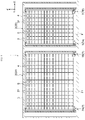
- a transport system 1 includes a plurality of stockers 2.
- a stacker crane 7 travels inside a stocker body 3 and an article is transferred between a plurality of shelves S provided inside the stocker body 3 and a storage/retrieval port (not illustrated) .
- the article transferred by the stacker crane 7 is stored in the stocker 2.
- the article is, for example, a container such as a FOUP (Front-Opening Unified Pod) to house wafers processed by a semiconductor manufacturing device or a liquid crystal manufacturing device and a reticle pod to house reticles used in a semiconductor manufacturing device or a liquid crystal manufacturing device.
- FOUP Front-Opening Unified Pod
- two (a plurality of) stockers 2A, 2B are arranged in a traveling direction of the stacker crane 7.
- two stacker cranes 7 (7A, 7B) are arranged inside of each stocker 2.
- the stocker 2 has the stocker body 3, a rack 4, and the stacker cranes 7A, 7B.
- the stocker 2 is supported by a stand 8 (refer to FIG.5 ).
- a traveling direction of the stacker crane 7 is referred to as a X direction (first direction)
- a vertical direction is referred to as a Z direction
- a horizontal direction perpendicular to the X direction and the Z direction is referred to as a Y direction (second direction).
- the stocker body 3 is formed, for example, in a hollow rectangular shape.
- a travel rail 31 on which the stacker crane 7 travels, and an auxiliary rail 32 arranged so as to face the travel rail 31 in the Z direction are laid on the stocker body 3 along the X direction.
- the stacker crane 7 travels (moves) along the travel rail 31 and the auxiliary rail 32.
- the stacker crane 7 transports an article between a shelf S and the storage/retrieval port, and transfers an article from/to the shelf S.
- the rack 4 is arranged in the stocker body 3 along the X direction.
- a pair of the racks 4 are arranged so as to face each other via the travel rail 31.
- the rack 4 is provided with a plurality of shelves S to house articles.
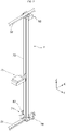
- the stacker crane 7 includes a travel unit 71, a mast 72, a transfer unit 75, and an auxiliary travel unit 90.
- the travel unit 71 has a traveling motor 78, a lifting motor 82, and a housing 85.
- the travel unit 71 travels along the travel rail 31.
- the travel unit 71 includes drive wheels which rotate and move along a top surface of the travel rail 31.
- the traveling motor 78 is a drive source of a traveling drive wheel.
- the lifting motor 82 is a drive source of an elevator 73.
- the housing 85 houses the traveling motor 78 and the lifting motor 82.
- FIG.2 illustrates a state in which the housing 85 is removed.
- the mast 72 is erected on the upper portion of the travel unit 71 in the Z direction.
- the transfer unit 75 transfers an article from/to the shelf S and transfers an article from/to the storage/retrieval port.
- the auxiliary travel unit 90 travels along the auxiliary rail 32.
- the auxiliary travel unit 90 includes a pair of drive wheels configured to rotate and move at both sides of the auxiliary rail 32.
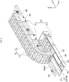
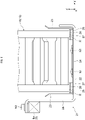
- the transport system 1 includes a cable unit 10.
- One end 10a of the cable unit 10 is connected with the stacker crane 7.
- the cable unit 10 moves in accordance with movement of the stacker crane 7.
- the cable unit 10 has a longitudinal shape.
- the cable unit 10 includes an upper portion 10x extending in one side of the X direction from the stacker crane 7, a U-shaped portion 10y extending so as to fold downward in a U shape from the upper portion 10x, and a lower portion 10z extending in the other side of the X direction from the U-shaped portion 10y.
- the cable unit 10 moves such that the one end 10a and the U-shaped portion 10y stroke (move) to one side or the other side accordingly.
- the cable unit 10 has a power cable 11 and a cableveyor 15.
- the power cable 11 is connected with the stacker crane 7 and with a power source unit (not illustrated) located in the stocker 2. Whereby, the stacker crane 7 is powered from the power source unit via the power cable 11. It is not especially limited to the power cable 11 and any cable having various shapes or specifications is usable.
- the cableveyor 15 internally houses the power cable 11 to protect the power cable 11. In addition, the cableveyor 15 guides the power cable 11 so that the said power cable 11 can follow movement of the stacker crane 7.
- the cableveyor 15 includes a cable housing unit.
- the cableveyor 15 has a movable end and a fixed end.
- the movable end of the cableveyor 15 is connected with the travel unit 71 of the stacker crane 7.
- the fixed end of the cableveyor 15 is attached and fixed to a table 8 (refer to FIG.5 ) of the stocker 2.
- the cableveyor 15 is configured to bend only in a direction around an axis along the Y direction. It is not especially limited to the cableveyor 15 and any component having various shapes or specifications is usable.
- the transport system 1 includes a cable guide 20 to guide the cable unit 10.
- the cable guide 20 has a fixed guide 21 and a guide roller 41.
- the fixed guide 21 constitutes a placement section provided so as to place the cable unit 10.
- the fixed guide 21 comes into contact with (abut) the cableveyor 15 of the lower portion 10z in the cable unit 10.
- the fixed guide 21 supports the lower portion lOz and guide it so as not to displace the lower portion 10z.
- the fixed guide 21 is provided so as to extend to one side of the X direction from a position adjacent to the fixed end of the cableveyor 15.
- the cable unit 10 is not illustrated in FIG.5 (nor in FIG.7 ).
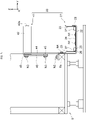
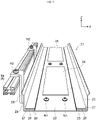
- the fixed guide 21 has a base 22, a first damping member 24, a second damping member 25, a protection member 26, and a flat and smooth member 27.
- the base 22, the thickness direction of which is the Z direction, is a plate-shape member extending in the X direction.
- the width of the base 22 in the Y direction corresponds to the width of the cableveyor 15 in the Y direction.
- the base 22 is supported in a cantilever manner by a girder member 8a of the stand 8 supporting the stocker 2 via a fixed guide attaching stay 28.
- the girder member 8a extends in the X direction below the stocker 2.
- the fixed guide attaching stay 28 is longitudinal in the Y direction and has a bended-plate shape.
- the fixed guide attaching stay 28 places the base 22 and is fixed to the said base 22 with a screw N1.
- a tip side of the fixed guide attaching stay 28 is bent upward at right angle and is adjacent to an outer surface of a restriction wall 23 (to be described later) .
- a base end side of the fixed guide attaching stay 28 is fixed to the top surface of the girder member 8a with a screw N2. Whereby, the fixed guide 21 is attached to the stand 8.
- the base 22 includes the restriction wall (restriction unit) 23.
- the restriction wall 23 is a plate-shaped member protruding upward from Y-directional both ends of the base 22.
- the restriction wall 23 is provided so as to continue to the Y-directional both ends of the base 22. In other words, the restriction wall 23 is provided so as to bend upward at right angle from the Y-directional both ends of the base 22.
- the restriction wall 23 restricts the Y-directional movement of the cableveyor 15 placed on the base 22.
- the first damping member 24 is provided on the base 22 and has damping properties higher than that of the base 22.
- the first damping member 24 has a rectangular sheet shape with a certain thickness in the Z direction.
- the first damping member 24 is adhesively fixed to the center portion of the base 22 in the Y direction.
- the first damping members 24 are intermittently arranged side by side along the X direction. Materials having a damping effect in general, such as asphalt, butyl rubber, or lead can be used as the first damping member 24.
- a material for the first damping member 24 is not especially limited. Any material that can realize its function can be used for the first damping member 24.
- "Damping" means to decrease vibration amplitude of a vibrating object or to damp vibration.
- the first damping member 24 repeats extension in accordance with vibration of the fixed guide 21 and converts vibration energy into heat energy to damp the vibration.
- the second damping member 25 is provided on the base 22 and is made of a material different from that of the first damping member 24.
- the second damping member 25 is thicker than the first damping member 24 and has a rectangular sheet shape.
- the second damping member 25 is adhesively fixed to the Y-directional both ends on the top surface of the base 22.
- the second damping member 25 is continuously arranged along the X direction. Resin materials such as rubber or urethane can be used as the second damping member 25.
- a material for the second damping member 25 is not especially limited. Any material that can realize its function can be used for the second damping member 25.
- the protection member 26 is provided on the second damping member 25 and is made of a material harder than that of the second damping member 25.
- the protection member 26 is thinner than the second damping member 25 and has a rectangular sheet shape.
- the protection member 26 is stacked on the top surface of the second damping member 25 and is adhesively fixed thereto.
- the protection member 26 is continuously arranged along the X direction.
- hard rubber and nylon can be used as the protection member 26.
- a material for the protection member 26 is not especially limited. Any material that can realize its function can be used for the protection member 26.
- the flat and smooth member 27 is provided on the protection member 26 and is made of a material having a friction coefficient lower than that of the protection member 26.
- the flat and smooth member 27 is thinner than the protection member 26 and has a rectangular sheet shape.
- the flat and smooth member 27 is stacked on the protection member 26 and is adhesively fixed thereto.
- the flat and smooth member 27 is continuously arranged along the X direction.
- NEW LIGHT registered trademark
- polyethylene, fluorine, Teflon registered trademark
- vinyl chloride or the like can be used as the flat and smooth member 27.
- a material for the flat and smooth member 27 is not especially limited. Any material that can realize its function can be used for the flat and smooth member 27.
- the cable unit 10 when the cable unit 10 is placed on the fixed guide 21, a part of the cable unit 10 comes into contact with the fixed guide 21.
- the bottom surfaces of both sides of the cableveyor 15 in the Y direction (width direction) come into contact with the top surfaces of the flat and smooth members 27.
- the both sides of the cableveyor 15 constitute contact surfaces R that come into contact with the fixed guide 21.
- the first damping member 24 does not support the cable unit 10 thereon. That is, the first damping member 24 is provided at a position that does not overlap with the both sides of the cableveyor 15 viewed from above. The first damping member 24 is arranged between the both sides of the cableveyor 15 viewed from above. The top surface of the first damping member 24 is not located above the top surface of the flat and smooth member 27. A gap is formed between the first damping member 24 and the cableveyor 15.
- the second damping member 25 supports the cable unit 10 thereon.
- the protection member 26 supports the cable unit 10 thereon.
- the flat and smooth member 27 supports the cable unit 10 thereon.
- the second damping member 25, the protection member 26, and the flat and smooth member 27 are provided at a position that overlaps the both sides of the cableveyor 15 viewed from above.
- a guide roller 41 comes into contact with the cableveyor 15 of the upper portion 10x in the cable unit 10.
- the guide roller 41 supports the upper portion 10x slidably in the X direction and guides the x-directional movement of the upper portion 10x.
- the guide roller 41 is arranged side-by-side at a certain interval along the X direction on the other side of the X direction from the fixed guide 21.
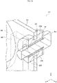
- the guide roller 41 includes a roller 42, a roller attaching stay 43, a stand attaching stay 44, and a grommet 45.
- the roller 42 is provided rotatably around a rotation axis 42a extending in the Y direction.
- the roller attaching stay 43 the thickness direction of which is the Y direction, has a plate shape.
- the base end side of the rotation axis 42a of the roller 42 is fixed to the upper portion of the roller attaching stay 43 with a screw or the like.
- the stand attaching stay 44 has a plate shape.
- a U-shaped notch viewed from the Y direction is formed on the upper portion of the stand attaching stay 44.
- the roller 42 is inserted through the notch.
- the roller attaching stay 43 is stacked at a certain interval at the back side of area between the upper portion and the center portion of the stand attaching stay 44. In this state, the said roller attaching stay 43 is fixed to the stand attaching stay 44 with screws N3 inserted into four corners thereof.
- the lower portion of the stand attaching stay 44 is fixed to the front surface of the girder member 8a with screws N4. Whereby, the guide roller 41 is attached to the stand 8.
- the grommet 45 is provided around an axis of the screw N3 via a collar 45a.
- the grommet 45 the Y direction of which is the axis direction, is a cylindrical member.
- the grommet 45 is made of rubber.
- the diameters of the front end 45f and the back end 45r of the grommet 45 in the axis direction are expanded.
- the front end 45f is arranged between the roller attaching stay 43 and the stand attaching stay 44.
- the back end 45r is arranged so as to abut against the back surface of the roller attaching stay 43.
- the edge of the roller attaching stay 43 and the edge of the stand attaching stay 44 are cut by intervention of the grommet 45, so that transmission of vibration caused by the guide roller 41 to the stand 8 is suppressed.
- the collar 45a is a cylindrical member arranged between the grommet 45 and the screw N3.
- the collar 45a prevents the grommet 45 from being excessively crushed in the Y direction by a tightening of the screw N3.
- a washer W is provided between head of the screw N3 and the back end 45r of the grommet 45 in the Y direction.
- the roller 42 rotates to guide the said X-directional movement of the cableveyor 15.
- the U-shaped portion 10y of the cable unit 10 strokes to one side of the X direction and moves such that the lower portion 10z increases.
- the cableveyor 15 bumps against and comes into contact with the fixed guide 21, which causes vibration.
- vibration caused by movement of the cable unit 10 can be suppressed by the first damping member 24.
- no abrasion is caused by a contact between the first damping member 24 and the cable unit 10 with each other, and no load of the cable portion 10 is applied to the first damping member 24, thus the first damping member 24 is not easily degraded. Therefore, durability of vibration suppression performance of the transport system 1 can be improved.
- a part of the cableveyor 15 of the cable unit 10 placed on the fixed guide 21 is in contact with the fixed guide 21, and the first damping member 24 is provided at a position that does not overlap with the relative contact surface R of the cable unit 10 viewed from above.
- a configuration can be specifically realized in which the first damping member 24 does not support the cable unit 10.
- the cable unit 10 placed on the fixed guide 21 is in contact with the fixed guide 21 at both sides of the cableveyor 15, and the first damping member 24 is arranged between the said both sides of the cable unit 10 viewed from above.
- a configuration can be specifically realized in which the first damping member 24 does not overlap with the contact surface R of the cable unit 10 viewed from above. Further, a space between the both sides can be utilized, thus enabling a space saving.
- the cable unit 10 has a power cable 11 and a cableveyor 15 that are connected to the stacker crane 7.
- the cableveyor 15 houses the power cable 11 therein and guides the power cable 11 so that the power cable 11 can follow movement of the stacker crane 7.
- the cable unit 10 can be specifically configured.
- the power cable 11 can follow movement of the stacker crane 7 while being protected.
- the stacker crane 7 is configured to move in the X direction.
- the base 22 has a restriction wall 23 to restrict the Y-directional movement of the cable unit 10 placed thereon.
- the restriction wall 23 can prevent the cable unit 10 from shifting in the Y direction.
- the fixed guide 21 has the second damping member 25 provided at the base 22 and made of a material different from that of the first damping member 24.
- the second damping member 25 supports the cable unit 10 thereon. Whereby, vibration caused by movement of the cable unit 10 can be further suppressed.
- the second damping member 25 is provided at a position that overlaps with the contact surface R where the cable unit 10 comes into contact with the fixed guide 21 viewed from above.
- a configuration can be specifically realized in which the second damping member 25 supports the cable unit 10.
- the fixed guide 21 has the protection member 26 provided on the second damping member 25 and made of a material harder than that of the second damping member 25. Whereby, the second damping member 25 can be protected.
- the fixed guide 21 has the flat and smooth member 27 provided on the protection member 26 and made of a material having a friction coefficient lower than that of the protection member 26. Whereby, abrasion of the protection member 26 caused by a contact with the cable unit 10 can be suppressed.
- the transport system 1 includes a stocker 2 having a plurality of shelves S to house an article and the stand 8 to support the stocker.
- the fixed guide 21 is attached to the stand 8. In this case, vibration caused by movement of the cable unit 10 is easily transmitted to the stocker 2 and the article via the stand 8. Suppression of vibration caused to the article is important, thus the above described effects to suppress vibration caused by movement of the cable unit 10 are especially effective.
- FIG. 11 is a view illustrating a noise test result of an embodiment and a comparison example.
- the embodiment corresponds to the above described transport system 1.
- asphalt is used as a material for the first damping member 24, and a styrene-based thermoplastic elastomer (TPS) is used as a material for the second damping member 25, acrylic rubber (ACM) is used as a material for the protection member 26, and NEW LIGHT is used as a material for the flat and smooth member 27.
- TPS thermoplastic elastomer
- ACM acrylic rubber
- NEW LIGHT is used as a material for the flat and smooth member 27.
- the comparison example is the same as the embodiment except the first damping member 24, the protection member 26, and the flat and smooth member 27 are not provided and urethane is used as the second damping member 25.
- Noise value is a relative value in a case where a noise value (db) of the comparison example is used as a standard. As a result of the noise test, it can be confirmed that the noise value of the embodiment is decreased by approximately 7 percentage with respect to the noise value of the comparison example.
- a position of the first damping member 24 is not especially limited as long as the position is a position at which the first damping member 24 does not support the cable unit 10.
- the first damping member 24 may be provided on the bottom surface of the base 22 or may be provided on the restriction wall 23 of the base 22.
- the number of the first damping member 24 to be provided is not especially limited.
- One first damping member 24 or a plurality of first damping members 24 may be provided.
- the first damping member 24 may be continuously arranged along the X direction.
- a signal cable being connected with the stacker crane 7 may be provided.
- the cableveyor 15 houses the signal cable therein, and guides the signal cable so that the signal cable can follow movement of the stacker crane 7.
- each configuration in the above described embodiments and variations is not limited to the above described materials and shapes. Various materials and shapes can be applied. Each configuration in the above described embodiments or variations can be optionally applied to each configuration in other embodiments or variations. A part of each configuration in the above described embodiments or variations can be appropriately omitted without departing from the scope of an aspect of the present invention.
- Transport system 2... Stocker, 7, 7A, 7B... Stacker crane (transport device), 8... Stand, 10... Cable unit, 11... Power cable, 15... Cableveyor (cable housing unit), 21... Fixed guide (placement section), 22... Base, 23... Restriction wall (restriction unit), 24... First damping member, 25... Second damping member, 26... Protection member, 27... Flat and smooth member, R... Contact surface, S... Shelf
Landscapes
- Engineering & Computer Science (AREA)
- General Engineering & Computer Science (AREA)
- Mechanical Engineering (AREA)
- Chemical & Material Sciences (AREA)
- Combustion & Propulsion (AREA)
- Physics & Mathematics (AREA)
- Acoustics & Sound (AREA)
- Aviation & Aerospace Engineering (AREA)
- Architecture (AREA)
- Civil Engineering (AREA)
- Structural Engineering (AREA)
- Warehouses Or Storage Devices (AREA)
- Insertion, Bundling And Securing Of Wires For Electric Apparatuses (AREA)
- Electric Cable Arrangement Between Relatively Moving Parts (AREA)
- Medicines That Contain Protein Lipid Enzymes And Other Medicines (AREA)
- Threshing Machine Elements (AREA)
Applications Claiming Priority (2)
| Application Number | Priority Date | Filing Date | Title |
|---|---|---|---|
| JP2020041079 | 2020-03-10 | ||
| PCT/JP2021/002629 WO2021181919A1 (fr) | 2020-03-10 | 2021-01-26 | Système de transport |
Publications (2)
| Publication Number | Publication Date |
|---|---|
| EP4089865A1 true EP4089865A1 (fr) | 2022-11-16 |
| EP4089865A4 EP4089865A4 (fr) | 2024-01-24 |
Family
ID=77671354
Family Applications (1)
| Application Number | Title | Priority Date | Filing Date |
|---|---|---|---|
| EP21767207.0A Pending EP4089865A4 (fr) | 2020-03-10 | 2021-01-26 | Système de transport |
Country Status (8)
| Country | Link |
|---|---|
| US (1) | US12304734B2 (fr) |
| EP (1) | EP4089865A4 (fr) |
| JP (1) | JP7294524B2 (fr) |
| KR (1) | KR102763295B1 (fr) |
| CN (1) | CN114930662B (fr) |
| IL (1) | IL295192B2 (fr) |
| TW (1) | TWI844765B (fr) |
| WO (1) | WO2021181919A1 (fr) |
Families Citing this family (2)
| Publication number | Priority date | Publication date | Assignee | Title |
|---|---|---|---|---|
| TWI895428B (zh) * | 2020-05-27 | 2025-09-01 | 德商易格斯股份有限公司 | 具有可撓性接頭連接器的拖鏈,以及用於該拖鏈的側板和接頭連接器 |
| DE202021104228U1 (de) * | 2021-08-06 | 2022-09-07 | Igus Gmbh | System zur Abstützung einer beweglichen Leitungsaufnahmeeinrichtung, Energieführungskette oder dgl. |
Family Cites Families (16)
| Publication number | Priority date | Publication date | Assignee | Title |
|---|---|---|---|---|
| JPS4986668U (fr) | 1972-11-14 | 1974-07-26 | ||
| DE29607228U1 (de) | 1996-04-22 | 1996-06-13 | Igus Spritzgußteile für die Industrie GmbH, 51147 Köln | Kanal für Energieführungsketten |
| US5944202A (en) * | 1997-11-18 | 1999-08-31 | Wylie; John F. | Material handling pushback |
| JP4266745B2 (ja) * | 2003-08-18 | 2009-05-20 | 株式会社椿本チエイン | ケーブル類保護案内装置 |
| JP4243161B2 (ja) | 2003-10-14 | 2009-03-25 | 矢崎総業株式会社 | 電線余長吸収装置 |
| JP2008089114A (ja) | 2006-10-03 | 2008-04-17 | Bridgestone Corp | 制振用ダンパー |
| JP4986668B2 (ja) * | 2007-03-23 | 2012-07-25 | Juki株式会社 | 表面実装装置 |
| JP2011106618A (ja) | 2009-11-19 | 2011-06-02 | Tsubakimoto Chain Co | ケーブル類保護案内装置用可動式ガイドローラ |
| CN202004386U (zh) | 2010-12-31 | 2011-10-05 | 上海市电力公司 | 应用于大桥敷设高压电缆的抗振支架系统 |
| JP5829868B2 (ja) | 2011-09-05 | 2015-12-09 | ポリマテック・ジャパン株式会社 | 粘性流体封入ダンパー |
| JP6061020B2 (ja) | 2013-02-12 | 2017-01-18 | 村田機械株式会社 | 保管棚 |
| KR101634659B1 (ko) | 2014-06-09 | 2016-07-08 | 한국전기연구원 | 산업용 로봇 이송 시스템의 소음 및 진동 저감 장치 |
| JP6201977B2 (ja) * | 2014-12-19 | 2017-09-27 | 村田機械株式会社 | 自動倉庫及びその運転方法 |
| JP6642028B2 (ja) | 2016-01-20 | 2020-02-05 | ティアック株式会社 | ケーブルホルダ |
| CN106494182B (zh) | 2016-10-17 | 2019-02-26 | 珠海格力电器股份有限公司 | 减振组件、车载空调及客车和基于电磁技术的减振方法 |
| JP6772997B2 (ja) | 2017-09-29 | 2020-10-21 | 株式会社オートネットワーク技術研究所 | ワイヤハーネス配索装置 |
-
2021
- 2021-01-26 US US17/909,929 patent/US12304734B2/en active Active
- 2021-01-26 IL IL295192A patent/IL295192B2/en unknown
- 2021-01-26 WO PCT/JP2021/002629 patent/WO2021181919A1/fr not_active Ceased
- 2021-01-26 CN CN202180008090.7A patent/CN114930662B/zh active Active
- 2021-01-26 JP JP2022505820A patent/JP7294524B2/ja active Active
- 2021-01-26 EP EP21767207.0A patent/EP4089865A4/fr active Pending
- 2021-01-26 KR KR1020227034485A patent/KR102763295B1/ko active Active
- 2021-03-08 TW TW110108076A patent/TWI844765B/zh active
Also Published As
| Publication number | Publication date |
|---|---|
| IL295192B2 (en) | 2024-12-01 |
| CN114930662A (zh) | 2022-08-19 |
| EP4089865A4 (fr) | 2024-01-24 |
| WO2021181919A1 (fr) | 2021-09-16 |
| US12304734B2 (en) | 2025-05-20 |
| TWI844765B (zh) | 2024-06-11 |
| IL295192B1 (en) | 2024-08-01 |
| US20230106446A1 (en) | 2023-04-06 |
| KR102763295B1 (ko) | 2025-02-04 |
| KR20220145406A (ko) | 2022-10-28 |
| TW202207790A (zh) | 2022-02-16 |
| JP7294524B2 (ja) | 2023-06-20 |
| JPWO2021181919A1 (fr) | 2021-09-16 |
| IL295192A (en) | 2022-09-01 |
| CN114930662B (zh) | 2024-12-17 |
Similar Documents
| Publication | Publication Date | Title |
|---|---|---|
| CN104956473B (zh) | 保管架 | |
| US20060226094A1 (en) | Glass cassette for loading glass substrates of display panels | |
| EP4089865A1 (fr) | Système de transport | |
| KR20130025316A (ko) | 프로브 카드 컨테이너 | |
| CN110255185A (zh) | 一种夹持装置 | |
| US20130264301A1 (en) | Hoist apparatus | |
| CN111994584A (zh) | 物品输送体 | |
| KR102267935B1 (ko) | 타워크레인 장치 | |
| US6511038B1 (en) | Apparatus for dampening vibrations of an automatic guided vehicle | |
| US20130058742A1 (en) | Transfer device | |
| JP2012051674A (ja) | 昇降装置 | |
| KR101399399B1 (ko) | 기판용 카세트의 재치대 | |
| WO2014043907A1 (fr) | Appareil de support et dispositif de stockage de cassette de substrat en verre | |
| CN221394717U (zh) | 专用于半导体板材的存放运输装置 | |
| JP2001163447A (ja) | 移載装置とこれを用いた無人搬送車 | |
| US20050036857A1 (en) | Automatic material handling system and stocker therefor | |
| KR102814329B1 (ko) | 기판 적재 장치 | |
| KR102808251B1 (ko) | 감쇠 유닛 및 이를 갖는 이송 장치 | |
| CN112081868A (zh) | 一种电气机械设备用减震支撑结构 | |
| KR102926245B1 (ko) | 선반 유닛 및 이를 갖는 스토커 | |
| CN209775780U (zh) | 贴合装置 | |
| JP2005335743A (ja) | 基板用カセット | |
| KR19990026577A (ko) | 액정 표시 장치용 글래스 스테이지 | |
| KR101218552B1 (ko) | 슬라이딩을 방지하는 기판이송로봇 | |
| JP3122728U (ja) | 免震装置 |
Legal Events
| Date | Code | Title | Description |
|---|---|---|---|
| STAA | Information on the status of an ep patent application or granted ep patent |
Free format text: STATUS: THE INTERNATIONAL PUBLICATION HAS BEEN MADE |
|
| PUAI | Public reference made under article 153(3) epc to a published international application that has entered the european phase |
Free format text: ORIGINAL CODE: 0009012 |
|
| STAA | Information on the status of an ep patent application or granted ep patent |
Free format text: STATUS: REQUEST FOR EXAMINATION WAS MADE |
|
| 17P | Request for examination filed |
Effective date: 20220812 |
|
| AK | Designated contracting states |
Kind code of ref document: A1 Designated state(s): AL AT BE BG CH CY CZ DE DK EE ES FI FR GB GR HR HU IE IS IT LI LT LU LV MC MK MT NL NO PL PT RO RS SE SI SK SM TR |
|
| DAV | Request for validation of the european patent (deleted) | ||
| DAX | Request for extension of the european patent (deleted) | ||
| A4 | Supplementary search report drawn up and despatched |
Effective date: 20240104 |
|
| RIC1 | Information provided on ipc code assigned before grant |
Ipc: F16F 15/08 20060101ALN20231221BHEP Ipc: F16F 7/00 20060101ALN20231221BHEP Ipc: H02G 11/00 20060101AFI20231221BHEP |