EP4089936A1 - Datenverarbeitungsverfahren und -vorrichtung - Google Patents
Datenverarbeitungsverfahren und -vorrichtung Download PDFInfo
- Publication number
- EP4089936A1 EP4089936A1 EP20921222.4A EP20921222A EP4089936A1 EP 4089936 A1 EP4089936 A1 EP 4089936A1 EP 20921222 A EP20921222 A EP 20921222A EP 4089936 A1 EP4089936 A1 EP 4089936A1
- Authority
- EP
- European Patent Office
- Prior art keywords
- network coded
- pdu
- coded packet
- network
- size
- Prior art date
- Legal status (The legal status is an assumption and is not a legal conclusion. Google has not performed a legal analysis and makes no representation as to the accuracy of the status listed.)
- Pending
Links
- 238000003672 processing method Methods 0.000 title abstract description 16
- 238000000034 method Methods 0.000 claims abstract description 105
- 238000004891 communication Methods 0.000 claims abstract description 65
- 238000012545 processing Methods 0.000 claims description 69
- 230000006870 function Effects 0.000 claims description 37
- 230000015654 memory Effects 0.000 claims description 37
- 238000004590 computer program Methods 0.000 claims description 20
- 230000006978 adaptation Effects 0.000 claims description 6
- 230000005540 biological transmission Effects 0.000 abstract description 33
- 230000003595 spectral effect Effects 0.000 abstract description 18
- 230000000875 corresponding effect Effects 0.000 description 22
- 238000013461 design Methods 0.000 description 22
- 230000008569 process Effects 0.000 description 21
- 230000007246 mechanism Effects 0.000 description 16
- 238000010586 diagram Methods 0.000 description 15
- 238000005516 engineering process Methods 0.000 description 12
- 239000004065 semiconductor Substances 0.000 description 7
- 230000007774 longterm Effects 0.000 description 6
- 239000013598 vector Substances 0.000 description 6
- 229910044991 metal oxide Inorganic materials 0.000 description 4
- 150000004706 metal oxides Chemical class 0.000 description 4
- 230000001360 synchronised effect Effects 0.000 description 4
- 230000008878 coupling Effects 0.000 description 3
- 238000010168 coupling process Methods 0.000 description 3
- 238000005859 coupling reaction Methods 0.000 description 3
- 230000009977 dual effect Effects 0.000 description 3
- 239000011159 matrix material Substances 0.000 description 3
- 238000010295 mobile communication Methods 0.000 description 3
- 229910000577 Silicon-germanium Inorganic materials 0.000 description 2
- 230000003190 augmentative effect Effects 0.000 description 2
- 230000009286 beneficial effect Effects 0.000 description 2
- 230000001413 cellular effect Effects 0.000 description 2
- 230000000295 complement effect Effects 0.000 description 2
- 230000000977 initiatory effect Effects 0.000 description 2
- 238000013507 mapping Methods 0.000 description 2
- 230000003287 optical effect Effects 0.000 description 2
- 230000011218 segmentation Effects 0.000 description 2
- 230000003068 static effect Effects 0.000 description 2
- 239000002699 waste material Substances 0.000 description 2
- JBRZTFJDHDCESZ-UHFFFAOYSA-N AsGa Chemical compound [As]#[Ga] JBRZTFJDHDCESZ-UHFFFAOYSA-N 0.000 description 1
- 241000288673 Chiroptera Species 0.000 description 1
- LEVVHYCKPQWKOP-UHFFFAOYSA-N [Si].[Ge] Chemical compound [Si].[Ge] LEVVHYCKPQWKOP-UHFFFAOYSA-N 0.000 description 1
- 230000009471 action Effects 0.000 description 1
- 230000002776 aggregation Effects 0.000 description 1
- 238000004220 aggregation Methods 0.000 description 1
- 238000013473 artificial intelligence Methods 0.000 description 1
- 238000006243 chemical reaction Methods 0.000 description 1
- 239000003795 chemical substances by application Substances 0.000 description 1
- 230000006835 compression Effects 0.000 description 1
- 238000007906 compression Methods 0.000 description 1
- 125000004122 cyclic group Chemical group 0.000 description 1
- 238000013500 data storage Methods 0.000 description 1
- 230000006837 decompression Effects 0.000 description 1
- 238000005562 fading Methods 0.000 description 1
- 230000008713 feedback mechanism Effects 0.000 description 1
- 239000013307 optical fiber Substances 0.000 description 1
- 239000000047 product Substances 0.000 description 1
- 238000011160 research Methods 0.000 description 1
- 238000013468 resource allocation Methods 0.000 description 1
- 238000001228 spectrum Methods 0.000 description 1
- 239000013589 supplement Substances 0.000 description 1
- 238000012546 transfer Methods 0.000 description 1
- 208000037918 transfusion-transmitted disease Diseases 0.000 description 1
Images






Classifications
-
- H—ELECTRICITY
- H04—ELECTRIC COMMUNICATION TECHNIQUE
- H04L—TRANSMISSION OF DIGITAL INFORMATION, e.g. TELEGRAPHIC COMMUNICATION
- H04L1/00—Arrangements for detecting or preventing errors in the information received
- H04L1/0001—Systems modifying transmission characteristics according to link quality, e.g. power backoff
- H04L1/0009—Systems modifying transmission characteristics according to link quality, e.g. power backoff by adapting the channel coding
-
- H—ELECTRICITY
- H04—ELECTRIC COMMUNICATION TECHNIQUE
- H04L—TRANSMISSION OF DIGITAL INFORMATION, e.g. TELEGRAPHIC COMMUNICATION
- H04L1/00—Arrangements for detecting or preventing errors in the information received
- H04L1/004—Arrangements for detecting or preventing errors in the information received by using forward error control
- H04L1/0076—Distributed coding, e.g. network coding, involving channel coding
-
- H—ELECTRICITY
- H04—ELECTRIC COMMUNICATION TECHNIQUE
- H04L—TRANSMISSION OF DIGITAL INFORMATION, e.g. TELEGRAPHIC COMMUNICATION
- H04L1/00—Arrangements for detecting or preventing errors in the information received
- H04L1/0001—Systems modifying transmission characteristics according to link quality, e.g. power backoff
- H04L1/0009—Systems modifying transmission characteristics according to link quality, e.g. power backoff by adapting the channel coding
- H04L1/0011—Systems modifying transmission characteristics according to link quality, e.g. power backoff by adapting the channel coding applied to payload information
-
- H—ELECTRICITY
- H04—ELECTRIC COMMUNICATION TECHNIQUE
- H04L—TRANSMISSION OF DIGITAL INFORMATION, e.g. TELEGRAPHIC COMMUNICATION
- H04L1/00—Arrangements for detecting or preventing errors in the information received
- H04L1/004—Arrangements for detecting or preventing errors in the information received by using forward error control
- H04L1/0041—Arrangements at the transmitter end
-
- H—ELECTRICITY
- H04—ELECTRIC COMMUNICATION TECHNIQUE
- H04L—TRANSMISSION OF DIGITAL INFORMATION, e.g. TELEGRAPHIC COMMUNICATION
- H04L1/00—Arrangements for detecting or preventing errors in the information received
- H04L1/004—Arrangements for detecting or preventing errors in the information received by using forward error control
- H04L1/0075—Transmission of coding parameters to receiver
-
- H—ELECTRICITY
- H04—ELECTRIC COMMUNICATION TECHNIQUE
- H04L—TRANSMISSION OF DIGITAL INFORMATION, e.g. TELEGRAPHIC COMMUNICATION
- H04L1/00—Arrangements for detecting or preventing errors in the information received
- H04L1/0078—Avoidance of errors by organising the transmitted data in a format specifically designed to deal with errors, e.g. location
- H04L1/0083—Formatting with frames or packets; Protocol or part of protocol for error control
-
- H—ELECTRICITY
- H04—ELECTRIC COMMUNICATION TECHNIQUE
- H04L—TRANSMISSION OF DIGITAL INFORMATION, e.g. TELEGRAPHIC COMMUNICATION
- H04L1/00—Arrangements for detecting or preventing errors in the information received
- H04L1/12—Arrangements for detecting or preventing errors in the information received by using return channel
- H04L1/16—Arrangements for detecting or preventing errors in the information received by using return channel in which the return channel carries supervisory signals, e.g. repetition request signals
- H04L1/18—Automatic repetition systems, e.g. Van Duuren systems
- H04L1/1867—Arrangements specially adapted for the transmitter end
Definitions
- This application relates to the communication field, and in particular, to a data processing method and apparatus.
- a random linear network coding (random linear network coding, RLNC) technology provides a transmission mechanism that considers both a delay and spectral efficiency.
- RLNC random linear network coding
- a transmit end codes a plurality of original data units to obtain a plurality of coded data units, and then the transmit end generates a plurality of coded packets.
- Each coded packet includes one coded data unit and a coding coefficient.
- a receive end may decode the coded data unit based on the coding coefficient, to obtain the original data unit.
- Embodiments of this application provide a data processing method and apparatus, to improve spectral efficiency in network coding-based data transmission.
- an embodiment of this application provides a data processing method.
- the method may be performed by a transmit end device (for example, a terminal or a network device), or may be performed by a component of the transmit end device, for example, a processor, a chip, or a chip system of the transmit end device (for example, the terminal or the network device).
- the method includes: generating a PDU based on a reference size and K network coded packets; generating a TB based on the PDU; and outputting the TB, where K is a positive integer, and the reference size is a size of a reference TB or a size of a reference PDU.
- the transmit end device may generate the TB based on the size of the reference TB or the reference PDU, so that the TB can include an integer quantity of network coded packets. This reduces cases in which some bits of a network coded packet are correctly transmitted but decoding cannot be performed by using the bits because a coding coefficient of the network coded packet is not determined, and improves spectral efficiency.
- the generating a PDU based on a reference size and K network coded packets includes: obtaining the K network coded packets based on the reference size; and generating the PDU based on the K network coded packets.
- the transmit end device may flexibly obtain the integer quantity of network coded packets based on the size of the reference TB or the reference PDU, so that data processing flexibility can be improved.
- the generating the PDU based on the K network coded packets includes: segmenting the last network coded packet in the K network coded packets to obtain a plurality of network coded packet segments, where a first network coded packet segment includes header information of the last network coded packet, the first network coded packet segment includes the first N network coded packet segments in the plurality of network coded packet segments, and N is a positive integer; and generating the PDU based on the first K-1 network coded packets and the first network coded packet segment in the K network coded packets.
- the PDU generated based on the first K-1 network coded packets and the first network coded packet segment includes header information of a network coded packet to which the first network coded packet segment belongs, so that a receive end device can perform, based on the header information, decoding by using the first network coded packet segment. Therefore, spectral efficiency is improved.
- header information of a first network coded packet includes information used to indicate a coding coefficient of the last network coded packet.
- the first network coded packet is a network coded packet in the first K-1 network coded packets.
- the receive end device when the first network coded packet is correctly transmitted, the receive end device can perform, based on the information used to indicate the coding coefficient of the last network coded packet, decoding by using a network coded packet segment other than the first network coded packet segment in the plurality of network coded packet segments. Therefore, spectral efficiency is improved.
- the data processing method further includes: adding segment header information of a second network coded packet segment.
- the second network coded packet segment is a network coded packet segment other than the first network coded packet segment in the plurality of network coded packet segments.
- the segment header information includes the information used to indicate the coding coefficient of the last network coded packet.
- the receive end device can perform, based on the segment header information of the second network coded packet segment, decoding by using the second network coded packet segment. Therefore, spectral efficiency is improved.
- the segment header information further includes information used to indicate an identifier of a network coded block to which the last network coded packet belongs.
- the receive end device can store the network coded packet/segment based on the identifier of the network coded block, to facilitate subsequent decoding and reduce a processing delay.
- the data processing method further includes: receiving request information, where the request information is used to request first header information, the first header information includes header information of a second network coded packet and/or segment header information of a third network coded packet segment, the second network coded packet is a network coded packet in the K network coded packets, and the third network coded packet segment is a segment of the last network coded packet in the K network coded packets; and sending, based on the request information, information used to indicate the first header information.
- the receive end device may request the transmit end device to retransmit the header information or the segment header information, without retransmitting a data part of the network coded packet or the network coded packet segment, to reduce resource overheads.
- a total size of the first K-1 network coded packets in the K network coded packets is less than the reference size, and a total size of the K network coded packets is greater than or equal to the reference size. Based on this possible implementation, because the total size of the K network coded packets used to generate the PDU is greater than or equal to the reference size, a size of the generated PDU may be greater than the size of the reference PDU, so that a code rate can be increased.
- a total size of the K network coded packets is less than or equal to the reference size, and a total size of the K network coded packets and a third network coded packet is greater than the reference size.
- the third network coded packet is a network coded packet other than the K network coded packets.
- a size of the TB is different from the size of the reference TB. Based on this possible implementation, because the size of the actually generated TB may be different from the size of the reference TB, the transmit end device does not need to generate the TB based on the size of the reference TB, so that data processing flexibility can be improved.
- a size of the PDU is different from the size of the reference PDU. Based on this possible implementation, because the size of the actually generated PDU may be different from the size of the reference PDU, the transmit end device does not need to generate the PDU based on the size of the reference PDU, so that data processing flexibility can be improved.
- the PDU is one of the following PDUs: a media access control MAC layer PDU, a radio link control RLC layer PDU, a backhaul adaptation protocol BAP layer PDU, a packet data convergence protocol PDCP layer PDU, or a PDU of a protocol layer having a network coding function.
- the data processing method further includes: determining, based on a PDU of a second protocol layer and with reference to a network coding parameter and/or a preset rule, a plurality of original data units included in a network coded block.
- the network coding parameter may include a size of the original data unit included in the network coded block and/or a quantity of original data units included in the network coded block.
- the preset rule may include: One PDU of the second protocol layer is used as one original data unit; or P PDUs of the second protocol layer are used as M original data units, where P is a positive integer, and M is a positive integer greater than or equal to 2.
- the generating the PDU based on the K network coded packets includes: using a k th network coded packet in the K network coded packets as a k th PDU, where header information of the k th network coded packet is used as a protocol header of the k th PDU, and k is a positive integer from 1 to K; or using a k th network coded packet in the K network coded packets as a payload of a k th PDU, and adding a protocol header of the k th PDU.
- the generating the PDU based on the K network coded packets includes: concatenating the K network coded packets to obtain the PDU.
- the PDU includes at least K protocol subheaders.
- the header information of the k th network coded packet in the K network coded packets is located in a k th protocol subheader of the PDU, where k is a positive integer from 1 to K.
- the first field after the k th protocol subheader of the PDU is padded with a network coded unit of the k th network coded packet.
- the K protocol subheaders of the PDU are sequentially arranged to form a protocol header of the PDU.
- the K protocol subheaders of the PDU are sequentially arranged, and the PDU further includes a (K+1) th protocol subheader.
- Information in the (K+1) th protocol subheader is used to indicate one or more of the following: a quantity of network coded units included in the PDU, the size of the PDU, and a size of a field other than the protocol header in the PDU.
- the generating the PDU based on the K network coded packets includes: concatenating the K network coded packets to obtain the PDU.
- the K network coded packets are used as payloads of the PDU.
- the PDU includes a protocol header.
- an embodiment of this application provides a communication apparatus, to implement the method according to any one of the first aspect or the possible implementations of the first aspect.
- the apparatus includes a corresponding unit or component configured to perform the foregoing method.
- the unit included in the apparatus may be implemented by using software and/or hardware.
- the apparatus may be, for example, a terminal, or a chip, a chip system, or a processor that can support the terminal in implementing the foregoing method.
- an embodiment of this application provides a communication apparatus, including a processor.
- the processor is coupled to a memory.
- the memory is configured to store a program or instructions.
- the apparatus is enabled to implement the method according to any one of the first aspect or the possible implementations of the first aspect.
- an embodiment of this application provides a communication apparatus.
- the apparatus is configured to implement the method according to any one of the first aspect or the possible implementations of the first aspect.
- an embodiment of this application provides a computer-readable medium.
- the computer-readable medium stores a computer program or instructions.
- a computer is enabled to perform the method according to any one of the first aspect or the possible implementations of the first aspect.
- an embodiment of this application provides a computer program product.
- the computer program product includes computer program code.
- the computer program code When the computer program code is run on a computer, the computer is enabled to perform the method according to any one of the first aspect or the possible implementations of the first aspect.
- an embodiment of this application provides a chip, including a processor.
- the processor is coupled to a memory.
- the memory is configured to store a program or instructions.
- the chip is enabled to implement the method according to any one of the first aspect or the possible implementations of the first aspect.
- any communication apparatus, chip, computer-readable medium, computer program product, communication system, or the like provided above is configured to perform the corresponding method provided above. Therefore, for beneficial effects that can be achieved by the communication apparatus, the chip, the computer-readable medium, the computer program product, the communication system, or the like, refer to beneficial effects in the corresponding method. Details are not described herein again.
- LTE long term evolution
- NR new radio
- the mechanism includes a hybrid automatic repeat request (hybrid automatic repeat request, HARQ) mechanism of a media access control (media access control, MAC) layer and an automatic repeat request (automatic repeat request, ARQ) mechanism of a radio link control (radio link control, RLC) layer.
- HARQ hybrid automatic repeat request
- MAC media access control
- ARQ automatic repeat request
- RLC radio link control
- the HARQ mechanism exists at both a transmit end and a receive end.
- HARQ operations at the transmit end include transmitting and retransmitting a transport block (transport block, TB), and receiving and processing acknowledgment (acknowledge, ACK) information or negative acknowledgment (negative acknowledge, NACK) information.
- HARQ operations at the receive end include receiving the TB, performing soft combination processing, and generating and feeding back ACK/NACK information.
- the receive end After receiving one TB sent by the transmit end, the receive end performs cyclic redundancy check (cyclical redundancy check, CRC) on the TB. If CRC check succeeds, the receive end feeds back positive acknowledgment (ACK) to the transmit end. If CRC check fails, the receive end feeds back negative acknowledgment (NACK). If receiving the ACK information, the transmit end performs new transmission. If receiving the NACK information, the transmit end performs retransmission.
- CRC cyclic redundancy check
- the ARQ mechanism is a function in an acknowledged mode (acknowledged mode, AM) at the RLC layer.
- ARQ operations at the transmit end include transmitting and retransmitting a protocol data unit (protocol data unit, PDU) or segment, receiving a state report from the receive end, receiving a HARQ sending failure indication from a lower layer, and the like.
- ARQ operations at the receive end include detecting whether an RLC layer PDU fails to be received, feeding back a data reception state to the transmit end by using an RLC layer state report, and the like.
- the state report may include a serial number (serial number, SN) of the RLC layer PDU that has been received by the receive end and an SN of the RLC layer PDU that is not received by the receive end.
- the receive end When detecting a packet loss, the receive end notifies, by using the RLC layer state report, the transmit end that a PDU, a segmented PDU, or a re-segmented PDU is not received, and the receive end requests the transmit end to retransmit the PDU.
- a relationship between the HARQ mechanism of the MAC layer and the ARQ mechanism of the RLC layer is as follows: After HARQ retransmission reaches a maximum quantity of retransmission times but still fails, ARQ retransmission is performed.
- the retransmission mechanism may be understood as blind retransmission.
- the transmit end when a transmit end does not receive HARQ feedback information from a receive end, or when the receive end does not support a HARQ feedback mechanism, the transmit end repeatedly sends data to the receive end.
- a sidelink (sidelink, SL) standard of a vehicle to everything (vehicle to everything, V2X) in an NR system supports blind retransmission of a TB.
- SL sidelink
- V2X vehicle to everything
- a resource allocation mode 2 of the SL standard at least an SL resource may be reserved for such blind retransmission.
- random linear network coding random linear network coding, RLNC
- a delay of a feedback-based retransmission mechanism is large, for example, round-trip time (round-trip time, RTT) of uplink HARQ processing for one time in a frequency-division duplex (frequency-division duplex, FDD) system is eight transmission time intervals (transmission time intervals, TTIs).
- RTT round-trip time
- FDD frequency-division duplex
- TTIs transmission time intervals
- An RLNC technology provides a transmission mechanism that considers both performance of a delay and spectral efficiency.
- a basic principle of RLNC-based network coding is shown in FIG. 1 .
- a transmit end divides, into a plurality of RLNC coded blocks, a data packet that needs to be sent.
- Each RLNC coded block includes M original data units, which are respectively represented by X 1 ,X 2 , ... ,X M . Then, the M original data units are coded to obtain N (N ⁇ M) coded packets.
- GF Galois field
- the GF field is a field including a finite quantity of elements, and GF(q) may be used to represent a GF field including q elements.
- a header of each coded packet Y i carries a coding coefficient vector used for generating the coded packet.
- a length of the coding coefficient vector is the same as the quantity M of the original data units in the coded block.
- the transmit end sends the N (N ⁇ M) coded packets to the receive end for each RLNC coded block. If a quantity of coded packets received by the receive end is not less than a quantity of original data units in the coded block, and a rank of a matrix including the coding coefficient vector carried in the header of the received coded packet is the quantity of original data units (that is, the receive end receives M linearly independent coded packets), the receive end may decode the coded packets to obtain the M original data units. For example, the receive end may construct a system of linear equations based on the coding coefficient. In the system of linear equations: X m , m e ⁇ 1,2, ... M ⁇ , that is, M unknowns to be solved. Then, the M original data units may be obtained by decoding the coded packets by using a linear equation theory.
- the receive end may combine received N coding coefficient vectors together to form a system of linear equations with M unknowns X 1 ,X 2 , ... ,X M .
- a coefficient matrix of the equations may be shown as follows, where [ g i ,1 , g i ,2 , ⁇ , g i,M ] is a coding coefficient vector of the i th coded packet.
- a factor such as channel noise, mobility fading, or user interference may cause errors in some coded packets received by the receive end.
- a quantity L of correctly received coded packets is not less than the quantity M of the original data units in the coded block.
- the receive end may still decode the coded packets to obtain the M original data units. Therefore, for the RLNC technology, the transmit end does not need to wait for a feedback request of the receive end before retransmission, and the transmit end may send several coded packets in advance to resist impact of a radio channel, to reduce a delay.
- a data processing procedure of each protocol layer in a communication system is as follows. After determining a size of a physical resource, a MAC layer of a transmit end determines a size of a TB or a size of an RLC layer PDU based on the size of the physical resource and channel state information, and notifies an RLC layer of the size of the TB or the size of the RLC layer PDU. The RLC layer sends the RLC layer PDU to the MAC layer based on the size of the TB or the size of the RLC layer PDU.
- each to-be-sent RLC layer service data unit (service data unit, SDU) at a current transmission opportunity
- the RLC layer performs a segmentation operation on the last to-be-sent RLC layer SDU at the current transmission opportunity.
- the RLC layer generates an RLC layer PDU, and sends the RLC layer PDU to the MAC layer.
- the MAC layer concatenates PDUs that are from the RLC layer to generate a TB, and sends the TB to a physical (physical, PHY) layer for processing.
- the communication system may be a long term evolution (long term evolution, LTE) system, a 5 th generation (5 th generation, 5G) communication system, an NR system, a wireless-fidelity (wireless-fidelity, Wi-Fi) system, a communication system related to the 3 rd generation partnership project (3 rd generation partnership project, 3GPP), a future evolved communication system, or the like.
- LTE long term evolution
- 5G 5 th generation
- 5G 5 th generation
- NR a wireless-fidelity (wireless-fidelity, Wi-Fi) system
- 3GPP 3 rd generation partnership project
- 3GPP 3 rd generation partnership project
- future evolved communication system or the like.
- the 5G communication system is a next generation communication system under research.
- the 5G communication system includes a non-standalone (non-standalone, NSA) 5G mobile communication system and a standalone (standalone, SA) 5G mobile communication system.
- the communication system may be further applied to a future-oriented communication technology, and are all applicable to the technical solutions provided in embodiments of this application.
- the foregoing communication system applicable to this application is only an example for descriptions, and a communication system applicable to this application is not limited thereto. This is uniformly described herein, and details are not described below again.
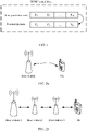
- a point-to-point single connectivity scenario for example, point-to-point transmission between user equipment (user equipment, UE) and UE, or point-to-point transmission between a base station and UE shown in FIG. 2a
- a multi-hop single connectivity scenario for example, multi-hop/relay (relay) transmission between a base station and UE shown in FIG. 2b
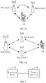
- a dual connectivity (dual connectivity, DC) scenario for example, dual connectivity transmission between two base stations and UE shown in FIG. 2c
- a multi-hop multi-connectivity scenario for example, multi-connectivity transmission between a plurality of base stations and UE shown in FIG. 2d .
- transmission is not limited to uplink transmission, downlink transmission, access link transmission, backhaul (backhaul) link transmission, or sidelink (sidelink) link transmission in this application.
- FIG. 3 shows a communication system according to an embodiment of this application.
- the communication system includes a transmit end device 20.
- the communication system may further include a receive end device 30.
- the transmit end device 20 and the receive end device 30 in this embodiment of this application may be devices of a same type.
- both the transmit end device 20 and the receive end device 30 are terminal devices.
- the transmit end device 20 and the receive end device 30 may be devices of different types.
- the transmit end device 20 is a terminal device and the receive end device 30 is a network device; or the transmit end device 20 is a network device and the receive end device 30 is a terminal device. This is not specifically limited in this embodiment of this application.
- the terminal device in embodiments of this application may be a device configured to implement a wireless communication function, for example, a terminal or a chip that may be used in the terminal.
- the terminal may be user equipment (user equipment, UE), an access terminal, a terminal unit, a terminal station, a mobile station, a remote station, a remote terminal, a mobile device, a wireless communication device, a terminal agent, a terminal apparatus, or the like in a 5G network or a future evolved public land mobile network (public land mobile network, PLMN).
- PLMN public land mobile network
- the access terminal may be a cellular phone, a cordless phone, a session initiation protocol (session initiation protocol, SIP) phone, a wireless local loop (wireless local loop, WLL) station, a personal digital assistant (personal digital assistant, PDA), a handheld device or a computing device having a wireless communication function, another processing device, vehicle-mounted device, or wearable device connected to a wireless modem, a virtual reality (virtual reality, VR) terminal device, an augmented reality (augmented reality, AR) terminal device, a wireless terminal in industrial control (industrial control), a wireless terminal in self driving (self driving), a wireless terminal in telemedicine (remote medical), a wireless terminal in a smart grid (smart grid), a wireless terminal in transportation safety (transportation safety), a wireless terminal in a smart city (smart city), a wireless terminal in a smart home (smart home), or the like.
- the terminal may be mobile or fixed.
- the network device in embodiments of this application is a device that connects a terminal device to a wireless network, and may be an evolved NodeB (evolved NodeB, eNB or eNodeB) or a next generation evolved NodeB (next generation evolved NodeB, ng-eNB) in long term evolution (long term evolution, LTE); or a next generation NodeB (next generation NodeB, gNB), a broadband network gateway (broadband network gateway, BNG), an aggregation switch, a non-3 rd generation partnership project (3 rd generation partnership project, 3GPP) access device, or the like in a 5 th generation (5 th generation, 5G) network or a future evolved PLMN.
- evolved NodeB evolved NodeB
- eNB evolved NodeB
- ng-eNB next generation evolved NodeB
- LTE long term evolution
- LTE long term evolution
- gNB next generation NodeB
- BNG broadband network gateway
- a base station in embodiments of this application may include base stations in various forms, for example, a macro base station, a micro base station (which is also referred to as a small cell), a relay station, and an access point. This is not specifically limited in embodiments of this application.
- the communication system shown in FIG. 3 is only used as an example, but is not intended to limit the technical solutions in this application.
- a person skilled in the art should understand that, in a specific implementation process, the communication system may further include another device. This is not limited.
- a structure of a protocol stack of the transmit end device 20 or the receive end device 30 in this embodiment of this application is shown in FIG. 4 , and sequentially includes a physical layer, a MAC layer, an RLC layer, and a packet data convergence protocol (packet data convergence protocol, PDCP) layer from bottom to top.
- the protocol stack may further include a backhaul adaptation protocol (backhaul adaptation protocol, BAP) layer.
- BAP backhaul adaptation protocol
- the physical layer is mainly used for telecommunication physical layer functions, such as modulation, demodulation, and multiple-antenna mapping.
- the MAC layer is mainly used for uplink and downlink scheduling and HARQ retransmission.
- the RLC layer is mainly used for segmentation and retransmission processing, and sequence control of higher layer data.
- the BAP layer is mainly used for backhaul link routing and bearer mapping.
- the PDCP layer is mainly used for header compression and decompression to reduce bit traffic that needs to be transmitted over a wireless interface.
- a name of a message (or information), a name of a parameter in the message (or information), or the like in the following embodiments of this application is only an example, and may be another name during specific implementation. This is not specifically limited in embodiments of this application.
- the transmit end device may perform some or all of steps in embodiments of this application.
- the steps are only examples. In embodiments of this application, other steps or variations of various steps may further be performed.
- the steps may be performed in a sequence different from a sequence presented in embodiments of this application, and not all steps in embodiments of this application need to be performed.
- FIG. 5 shows a data processing method according to an embodiment of this application.
- the data processing method includes the following steps.
- a transmit end device generates a PDU based on a reference size and K network coded packets.
- the reference size (size) is a size of a reference TB, a size of a reference PDU, or a size of a reference SDU, where K is a positive integer.
- the network coded packet may be a data packet obtained by performing network coding on an original data unit and adding header information or adding header information and other information.
- the "size” may alternatively be understood as a “length”, and the “size” and the “length” can be interchanged with each other. This is uniformly described herein, and details are not described in the following embodiments.
- the reference TB may be a TB to be generated by the transmit end device.
- the reference PDU may be a PDU of a first protocol layer required for generating the reference TB.
- the reference SDU may be an SDU of the first protocol layer required for generating the reference PDU.
- the reference size may be determined by the transmit end device based on a size of a physical resource and/or channel state information, or may be semi-statically configured by a network device. This is not specifically limited in this embodiment of this application.
- the first protocol layer may be one of the following: a MAC layer, an RLC layer, a BAP layer, a PDCP layer, or a protocol layer having a network coding function.
- the protocol layer having the network coding function may be a new protocol layer other than the MAC layer, the RLC layer, the BAP layer, and the PDCP layer.
- the protocol layer may be referred to as a network coding layer.
- the protocol layer may be located above the PDCP layer, located above the BAP layer, located between the PDCP layer and the RLC layer, located between the RLC layer and the MAC layer, or located between the MAC layer and a physical layer. This is not specifically limited in this embodiment of this application.
- the size of the reference SDU is less than or equal to the size of the reference PDU, and the size of the reference PDU is less than or equal to the size of the reference TB.
- the transmit end device may determine the size of the reference SDU based on the size of the reference PDU. Likewise, the transmit end device may determine the size of the reference PDU based on the size of the reference SDU. The transmit end device may further determine the size of the reference PDU and/or the size of the reference SDU based on the size of the reference TB.
- the reference TB may be understood as the reference PDU. To be specific, the reference TB and the reference PDU are the same, and have a same size.
- a transmit end device generates a PDU based on a reference size and K network coded packets may include: The transmit end device obtains the K network coded packets based on the reference size, and then generates the PDU based on the K network coded packets.
- that the transmit end device obtains the K network coded packets based on the reference size may include: The transmit end device determines the size of the reference PDU or the reference SDU based on the reference size, and then obtains the K network coded packets based on the size of the reference PDU or the reference SDU.
- the K network coded packets may be to-be-sent network coded packets buffered by the transmit end device.
- that the transmit end device obtains the K network coded packets may be understood as follows: The transmit end device selects the K network coded packets from to-be-sent network coded packets.
- the following relationship may exist between a total size of the K network coded packets and the reference size:
- Relationship 1 A total size of the first K-1 network coded packets in the K network coded packets is less than the reference size, and the total size of the K network coded packets is greater than or equal to the reference size.
- the network coded packets to be sent by the transmit end device are network coded packets 1 to 5.
- a size of each network coded packet is 1000 bytes, and the reference size is 1500 bytes.
- the size of 1000 bytes of the network coded packet 1 is less than the reference size of 1500 bytes.
- a total size of 2000 bytes of the network coded packet 1 and the network coded packet 2 is greater than the reference size of 1500 bytes.
- the transmit end device may determine that K is 2, and the K network coded packets are the network coded packet 1 and the network coded packet 2.
- Relationship 2 The total size of the K network coded packets is less than or equal to the reference size, and a total size of the K network coded packets and a third network coded packet is greater than the reference size.
- the third network coded packet is a network coded packet other than the K network coded packets.
- the network coded packets to be sent by the transmit end device are network coded packets 1 to 5.
- a size of each network coded packet is 1000 bytes, and the reference size is 1500 bytes.
- the size of 1000 bytes of the network coded packet 1 is less than the reference size of 1500 bytes.
- a total size of 2000 bytes of the network coded packet 1 and the network coded packet 2 is greater than the reference size of 1500 bytes.
- the transmit end device may determine that K is 1, each of the K network coded packets is the network coded packet 1, and the third network coded packet is the network coded packet 2.
- the reference size in the foregoing two relationships may be replaced with the size of the reference PDU or the size of the reference SDU.
- the transmit end device determines the size of the reference PDU or the reference SDU based on the size of the reference TB, and then compares the size of the reference PDU or the reference SDU with the total size of the K network coded packets.
- the operation of generating, by the transmit end device, the PDU based on the reference size and the K network coded packets may be completed by a first protocol layer entity of the transmit end device.
- the reference size when the reference size is determined by the transmit end device, for example, the reference size may be determined by a MAC layer entity of the transmit end device.
- the MAC layer entity may send size indication information to the first protocol layer entity, to indicate the reference size.
- the transmit end device generates a TB based on the PDU.
- the PDU is the PDU generated in step S501.
- that the transmit end device generates a TB based on the PDU may include: The transmit end device adds, to the PDU, a protocol header of each of the first protocol layer to the MAC layer (including the MAC layer), to obtain the TB.
- S503 The transmit end device outputs the TB.
- the TB is the TB generated in step S502.
- the transmit end device outputs the TB may be: The transmit end device sends the TB to a receive end device.
- that the transmit end device outputs the TB may be: The MAC layer entity of the transmit end device sends an MAC layer PDU to a physical layer entity of the transmit end device, where the MAC layer PDU is referred to as the TB at the physical layer.
- the PDU may be generated based on an integer quantity of network coded packets, and then the TB is generated based on the PDU, so that the generated TB includes the integer quantity of network coded packets, a case in which some bits of a network coded packet are correctly transmitted but decoding cannot be performed by using the bits can be avoided, thereby improving spectral efficiency.
- the data processing method provided in this embodiment of this application further includes the following step S504.
- S504 The transmit end device generates R network coded packets.
- the R network coded packets are network coded packets to be sent by the transmit end device, where R is a positive integer greater than or equal to K.
- the transmit end device may generate the R network coded packets by using the following steps.
- Each of the X network coded blocks includes a plurality of original data units, and the network coded block is uniquely identified by using a block identity (block identity, block ID).
- the "network coded block” in this embodiment of this application may also be referred to as a "network coded group”.
- the network coded group is uniquely identified by using a group identity (group ID).
- group ID group identity
- the "network coded block” may also be referred to as a "network coded batch”, and correspondingly, each network coded batch is uniquely identified by using a batch identity (batch ID).
- batch ID batch identity
- the “network coded block” may also be referred to as a “network coded generation”, and correspondingly, each network coded generation is uniquely identified by using a generation identity (generation ID).
- generation ID generation identity
- the "data unit” in this embodiment of this application may also be referred to as a "data segment", a “data block”, or a “data packet”, and the four can be replaced with each other. This is not specifically limited in this embodiment of this application.
- sizes of different original data units included in a same network coded block may be the same or different.
- Quantities of the original data units included in different network coded blocks may be the same or different. This is not specifically limited in this embodiment of this application.
- the transmit end device may determine, based on a PDU of a second protocol layer and with reference to a network coding parameter and/or a preset rule, the plurality of original data units included in each network coded block.
- the second protocol layer is an upper-layer protocol layer of the first protocol layer.
- An upper-layer protocol layer of a protocol layer is the last protocol layer at which data is processed before the protocol layer.
- the network coding parameter may include a size of the original data unit included in the network coded block and/or a quantity of original data units included in the network coded block.
- the size of the original data unit is less than or equal to a first threshold.
- the network coding parameter and/or the first threshold may be configured by the network device, may be predefined, or may be determined by the transmit end device. This is not specifically limited in this embodiment of this application.
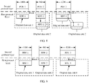
- sizes of the PDUs are respectively 1000 bytes, 980 bytes, and 1200 bytes
- the first threshold is 2000 bytes
- X is 2
- the network coding parameter the size of the original data unit included in the network coded block is 1000 bytes
- the quantity of original data units included in the network coded block is 2.
- the transmit end device determines, based on a PDU of a second protocol layer and with reference to a network coding parameter, the plurality of original data units included in the network coded block may be: The transmit end device determines that the PDU that is of the second protocol layer and whose size is 1000 bytes and the PDU that is of the second protocol layer and whose size is 980 bytes belong to a network coded block 1, and the PDU that is of the second protocol layer and whose size is 1200 bytes belongs to a network coded block 2.
- the transmit end device performs zero-padding on the PDU that is of the second protocol layer and whose size is 980 bytes in the network coded block 1 to 1000 bytes.
- the transmit end device first segments the PDU that is of the second protocol layer and whose size is 1200 bytes in the network coded block 2, and then performs zero-padding to obtain two original data units whose sizes each are 1000 bytes.
- the PDU of the second protocol layer may be considered as the SDU of the first protocol layer. Therefore, in FIG. 8 , a PDU 1 of the second protocol layer is written as an SDU 1 at the first protocol layer, and so on. Subsequently, a similar accompanying drawing may be understood based on this. This is uniformly described herein, and details are not described in the following embodiments again.
- the preset rule may include: One PDU of the second protocol layer is used as one original data unit; or P PDUs of the second protocol layer are used as M original data units, where P is a positive integer, and M is a positive integer greater than or equal to 2.
- the transmit end device may use the first two PDUs of the second protocol layer as two original data units in the network coded block 1, and use the last PDU of the second protocol layer as an original data unit in the network coded block 2.
- the transmit end device may use the first two PDUs of the second protocol layer as two original data units in the network coded block 1, and equally divide the last PDU of the second protocol layer into two original data units in the network coded block 2.
- the transmit end device determines, based on a PDU of a second protocol layer and with reference to a preset rule, the plurality of original data units included in the network coded block may be:
- the transmit end device equally divides the P PDUs of the second protocol layer into the M original data units. For example, as shown in FIG. 10b , P is 3, M is 4, X is 2, and sizes of the three PDUs are respectively 1000 bytes, 800 bytes, and 1200 bytes.
- the transmit end device may use the first 750 bytes of a first PDU as an original data unit in the network coded block 1, use the last 250 bytes of the first PDU and the first 500 bytes of a second PDU as another original data unit in the network coded block 1, use the last 300 bytes of the second PDU and the first 450 bytes of a third PDU as an original data unit in the network coded block 2, and use the last 750 bytes of the third PDU used as another original data unit in the network coded block 2.
- the method for determining the original data units shown in FIG. 8, FIG. 9 , FIG. 10a, or FIG. 10b is only an example for descriptions in this embodiment of this application. There may be another determining method in actual application. The method for determining the original data units is not limited in this embodiment of this application.
- the transmit end device generates the R network coded packets based on the X network coded blocks.
- the transmit end device may separately perform, by using the network coded block as a granularity, network coding on the plurality of original data units included in each network coded block to obtain R network coded data units in total. Then, header information corresponding to an i th network coded data unit in the R network coded data units is added, to obtain an i th network coded packet, where i is a positive integer from 1 to R.
- the header information corresponding to the i th network coded data unit may include information used to indicate a coding coefficient of the i th network coded packet and/or an identifier of a network coded block x.
- the coding coefficient of the i th network coded packet is a coefficient used when network coding is performed on the original data units to generate the i th network coded data unit.
- the network coded block x is a network coded block corresponding to the i th network coded data unit.
- the i th network coded data unit may be obtained after network coding is performed on a plurality of original data units included in the network coded block x, where x is a positive integer from 1 to X.
- the header information corresponding to the i th network coded data unit may be understood as header information of the i th network coded packet, and the header information corresponding to the i th network coded data unit is referred to as the header information of the i th network coded packet in the following embodiment of this application.
- the network coded block x may also be understood as a network coded block to which the i th network coded unit belongs or a network coded block to which the i th network coded packet belongs.
- the header information of the i th network coded packet may further include one or more of the following: identification information of the i th network coded packet in the network coded block x to which the i th network coded packet belongs, information about a quantity of original data units included in the network coded block x to which the i th network coded packet belongs, or a size of the i th network coded data unit.
- the header information of the i th network coded packet may further include information used to indicate a coding coefficient of a j th network coded packet in the R network coded packets, where j is a positive integer from 1 to R, and j is unequal to i.
- the header information of the i th network coded packet may include information used to indicate a coding coefficient of another network coded packet.
- decoding may be performed by using the correctly transmitted bits of the j th network coded packet and by using the information that is included in the header information of the correctly transmitted i th network coded packet and that is used to indicate the coding coefficient of the j th network coded packet.
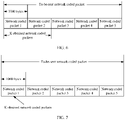
- the transmit end device performs network coding on the plurality of original data units included in the network coded block x, where the network coded block x includes four original data units, and five network coded data units are obtained after network coding.
- FIG. 11 shows a process of performing network coding and adding the header information by the transmit end device, where NC refers to network coding.
- a coding scheme used when the transmit end device performs network coding on the original data unit may be predefined, may be preconfigured by the network device, or may be determined by the transmit end device.
- the coding scheme may be one of the following: RLNC, deterministic linear network coding, batch sparse code (batch sparse code, BATS) coding, erasure code (erasure code) coding, and fountain code (fountain code) coding.
- RLNC deterministic linear network coding
- batch sparse code batch sparse code
- BATS erasure code
- fountain code fine code
- the transmit end device when the transmit end device performs network coding on the plurality of original data units included in the network coded block x, if sizes of the plurality of original data units included in the network coded block x are different, the transmit end device may perform processing by using the following two possible implementations.
- the transmit end device may supplement, to a standard size, an original data unit whose size is less than the standard size in the plurality of original data units included in the network coded block x, to obtain a plurality of adjusted original data units, and perform network coding on the plurality of adjusted original data units.
- the standard size may be a size of an original data unit with a longest size in the plurality of original data units included in the network coded block x, may be a preset size, or may be a size preconfigured by the network device.
- the network coded block x includes four original data units, sizes of the four original data units are different, and the standard size is the size of the original data unit with the longest size in the four original data units.
- a process in which the transmit end device performs network coding on the original data unit in the network coded block x may be shown in FIG. 12 .
- the transmit end device may determine a plurality of original data unit groups.
- Each of the plurality of original data unit groups includes a data segment of at least one of the plurality of original data units included in the network coded block x. Then, the transmit end device performs network coding on the data segment in the plurality of original data unit groups.
- the transmit end device may align the first bits of the plurality of original data units included in the network coded block x, and determine a length-aligned part of each original data unit as a data segment in one original data unit group.
- the first original data unit group includes a data segment S1 of an original data unit 1, a data segment S1 of an original data unit 2, a data segment S1 of an original data unit 3, and an original data unit 4.
- the second original data unit group includes a data segment S2 of the original data unit 1, a data segment S2 of the original data unit 2, and a data segment S2 of the original data unit 3.
- the third original data unit group includes a data segment S3 of the original data unit 2.
- the transmit end device performs network coding by using the original data unit group as a granularity. For example, as shown in FIG. 13 , after network coding is performed on the data segments in the first original data unit group, coded segments C11, C12, C13, and C14 are obtained. After network coding is performed on the data segments in the second original data unit group, coded segments C21, C22, and C23 are obtained. After network coding is performed on the data segment in the third original data unit group, a coded segment C31 is obtained.
- the transmit end device may use one or more coded segments corresponding to each original data unit group as one network coded data unit, for example, use C11, C12, C13, and C14 as one network coded data unit; or the transmit end device may use one coded segment as one network coded data unit, for example, use C11 as one network coded data unit.
- the transmit end device may further use one or more coded segments corresponding to a same coding coefficient as one network coded data unit.
- the network coding method is RLNC
- data segments belonging to a same original data unit use same a coding coefficient during network coding
- coding coefficients corresponding to coded segments in a same row are the same. Therefore, C11 and C12 may be used as one network coded data unit, and so on.
- the coded segments with the same network coding coefficient are used as one network coded data unit, when header information of the network coded data unit is added, that the header information includes a plurality of pieces of information used to indicate different coding coefficients may be avoided, thereby reducing complexity of the header information and reducing resource wastes during transmission.
- the transmit end device may alternatively not align the first bits of the plurality of original data units, but aligns some data segments, and then determines a length-aligned part of each original data unit as a data segment in one original data unit group.
- sizes of four original data units included in the network coded block x are different.
- three original data unit groups may also be determined based on a length-aligned part of each original data unit.
- a method for separately performing network coding on the three original data unit groups and determining a network coded data unit is similar to the method shown in FIG. 13 , and reference may be made to the foregoing related descriptions. Details are not described herein again.
- the transmit end device may obtain to-be-sent network coded packets, and may obtain the K network coded packets from the to-be-sent network coded packets based on the reference size.
- the transmit end device generates the PDU based on the K network coded packets in the foregoing step.
- the PDU generated by the transmit end device may include all of the K network coded packets, or may include some network coded packets and segments of the remaining network coded packets in the K network coded packets.
- the PDU generated by the transmit end device includes all of the K network coded packets.
- step S501 in a case in which the transmit end device compares the size of the reference PDU with the total size of the K network coded packets when obtaining the K network coded packets:
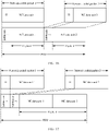
- a transmit end device generates a PDU based on K network coded packets may include: The transmit end device uses a k th network coded packet in the K network coded packets as a k th PDU. Header information of the k th network coded packet is used as a protocol header of the k th PDU, where k is a positive integer from 1 to K. That is, the transmit end device uses a network coded packet as a PDU. For example, K is 2.
- the PDU generated based on the K network coded packets may be shown in FIG. 15 .
- the PDU includes at least K protocol subheaders. Header information of a k th network coded packet in the K network coded packets is located in a k th protocol subheader of the PDU, where k is a positive integer from 1 to K.
- the header information of the k th network coded packet is used as the k th protocol subheader of the PDU, to be specific, the k th protocol subheader of the PDU does not include other information other than the header information of the k th network coded packet.
- the header information of the k th network coded packet is used as a part of information in the k th protocol subheader of the PDU, to be specific, in addition to the header information of the k th network coded packet, the k th protocol subheader of the PDU further includes other information.
- the header information of the k th network coded packet is used as the k th protocol subheader of the PDU is used for description.
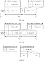
- the PDU may have the following three formats.
- K is 2.
- the PDU generated based on the K network coded packets may be shown in FIG. 16 .
- the K protocol subheaders of the PDU are sequentially arranged to form a protocol header of the PDU.
- K is 2.
- the PDU generated based on the K network coded packets may be shown in FIG. 17 .
- the K protocol subheaders of the PDU are arranged sequentially, and the PDU further includes a (K+1) th protocol subheader.
- Information in a (K+1) th protocol subheader of the PDU is used to indicate one or more of the following: a quantity of network coded units included in the PDU, a size of the PDU, and a size of a field other than the protocol header in the PDU.
- K is 2.
- the PDU generated based on the K network coded packets may be shown in FIG. 18 .
- HT represents the (K+1) th protocol subheader of the PDU.
- the size of the generated PDU is greater than or equal to the size of the reference PDU.
- a size of the TB generated in step S502 is greater than or equal to the size of the reference TB.
- the size of the generated PDU is less than or equal to the size of the reference PDU.
- the size of the TB generated in step S502 is less than or equal to the size of the reference TB.
- step S501 in a case in which the transmit end device compares the size of the reference SDU with the total size of the K network coded packets when obtaining the K network coded packets, that a transmit end device generates a PDU based on K network coded packets may include: The transmit end device determines a payload based on the K network coded packets, and then the transmit end device generates the PDU based on the payload.
- An example is as follows.
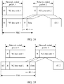
- a transmit end device generates a PDU based on K network coded packets may include: The transmit end device uses the k th network coded packet in the K network coded packets as a payload of a k th PDU, and adds a protocol header of the k th PDU to obtain the k th PDU. That is, the transmit end device uses a network coded packet as a payload of a PDU.
- K is 2.
- the PDU generated based on the K network coded packets may be shown in FIG. 19 , where HI is a protocol header of the first PDU added by the transmit end device, and H2 is a protocol header of the second PDU added by the transmit end device.
- a transmit end device generates a PDU based on K network coded packets may include: The transmit end device concatenates the K network coded packets to obtain the PDU.
- the K network coded packets are used as payloads of the PDU.
- the PDU includes a protocol header. Information in the protocol header is used to indicate a quantity of network coded units included in the PDU and/or a size of the PDU. For example, K is 2.
- the PDU generated based on the K network coded packets may be shown in FIG. 20a or shown in FIG. 20b .
- a size of the payload determined by the transmit end device is greater than or equal to the size of the reference SDU.
- the size of the generated PDU is greater than or equal to the size of the reference PDU.
- the size of the TB generated in step S502 is greater than or equal to the size of the reference TB.
- the size of the payload determined by the transmit end device is less than or equal to the size of the reference SDU.
- the size of the generated PDU is less than or equal to the size of the reference PDU.
- the size of the TB generated in step S502 is less than or equal to the size of the reference TB.
- the protocol header or the protocol subheader of the PDU may further include information used to indicate one or more of the following: the quantity of network coded units included in the PDU, the size of the PDU, and the size of the field other than the protocol header in the PDU.
- the transmit end device may perform zero-padding on the K network coded packets, so that a total size of the K network coded packets on which zero-padded is performed is equal to the reference size, and then the transmit end device generates the PDU based on the K network coded packets on which zero-padded is performed.
- the foregoing method for generating a PDU is also applicable when the transmit end device generates the PDU based on the network coded packet at a subsequent transmission opportunity.
- the transmit end device outputs the TB in step S503 includes: The transmit end device sends the TB to the receive end device.
- the receive end device may store, based on a network coded block to which the K network coded packets included in the TB belong, and then perform, based on header information of network coded packets belonging to a same network coded block, decoding on the network coded packets belonging to the same network coded block, to obtain an original data unit.
- the physical layer entity of the receive end device may perform CRC check on the TB. If CRC check is correct, the physical layer entity delivers a PDU of the first protocol layer included in the TB to a first protocol layer entity.
- the first protocol layer entity parses the PDU to obtain the K network coded packets included in the PDU, stores the K network coded packets based on the network coded block, and then performs decoding to obtain an original data unit.
- the PDU generated by the transmit end device includes some coded packets and segments of the remaining coded packets in the K network coded packets.
- a transmit end device generates a PDU based on K network coded packets may include: The transmit end device segments the last network coded packet in the K network coded packets to obtain a plurality of network coded packet segments, and generates the PDU based on the first K-1 network coded packets and a first network coded packet segment in the K network coded packets.
- the first network coded packet segment includes header information of the last network coded packet.
- the first network coded packet segment includes the first N network coded packet segments in the plurality of network coded packet segments, where N is a positive integer.
- the first network coded packet segment includes header information of the last network coded packet may be understood as follows:
- the 1 st network coded packet segment in the N network coded packet segments included in the first network coded packet segment includes the header information of the last network coded packet.
- each of the N network coded packet segments included in the first network coded packet segment includes the header information of the last network coded packet.
- the transmit end device may add the header information of the last network coded packet to the last N-1 network coded packet segments included in the first network coded packet segment.
- K is equal to 2
- N is equal to 1.
- the transmit end device segments the last network coded packet (a network coded packet 2) to obtain two network coded packet segments #2-1 and #2-2, where the first network coded packet segment is the network coded packet segment #2-1, and the network coded packet segment #2-1 includes header information of the network coded packet 2, the transmit end device finally generates the PDU based on a network coded packet 1 and the network coded packet segment #2-1.
- header information of the first network coded packet may further include information used to indicate a coding coefficient of the last network coded packet.
- the first network coded packet is one or more network coded packets of the first K-1 network coded packets.
- the transmit end device finally generates the PDU based on the network coded packet 1 and the network coded packet segment #2-1, the network coded packet 1 and the network coded packet segment #2-1 are sent at a current transmission opportunity, and the network coded packet segment #2-2 may be sent at a next transmission opportunity.
- the network coded packet segment #2-2 does not include information used to indicate a coding coefficient of the network coded packet 2
- the receive end device cannot obtain the information used to indicate the coding coefficient of the network coded packet 2 based on the network coded packet segment #2-2
- the receive end device may not perform decoding by using the network coded packet segment #2-2.
- header information of the network coded packet 1 includes the information used to indicate the coding coefficient of the network coded packet 2
- the receive end device may obtain the information used to indicate the coding coefficient of the network coded packet 2 based on the header information of the network coded packet 1. In this way, during subsequent decoding, the receive end device may perform, based on the information used to indicate the coding coefficient of the network coded packet 2, decoding by using the network coded packet segment #2-2.
- the receive end device can perform, based on the information used to indicate the coding coefficient of the last network coded packet, decoding by using a network coded packet segment other than the first network coded packet segment in the plurality of network coded packet segments. Therefore, spectral efficiency is improved.
- the transmit end device may further add segment header information of a second network coded packet segment.
- the second network coded packet segment is a network coded packet segment (for example, the network coded packet segment #2-2 shown in FIG. 21 ) other than the first network coded packet segment in the plurality of network coded packet segments.
- the segment header information is the information used to indicate the coding coefficient of the last network coded packet.
- the transmit end device may use the second network coded packet segment and the segment header information of the second network coded packet segment as a new network coded packet, store the new network coded packet, and send the new network coded packet at a next transmission opportunity.
- the 1 st network coded packet in the K network coded packets may include a segment of the last network coded packet and segment header information of the last network coded packet at a previous transmission opportunity.
- a format of the obtained new network coded packet may be shown in FIG. 22 , where Hs represents the segment header information of the second network coded packet segment.
- decoding based on the segment header information of the second network coded packet segment, may be performed by using the second network coded packet segment. Therefore, spectral efficiency is improved.
- the segment header information of the second network coded packet segment may further include one or more of the following: information used to indicate an identifier of a network coded block to which the last network coded packet belongs, information used to indicate a length of the second network coded packet segment, information used to indicate a location of the second network coded packet segment in the plurality of network coded packet segments, or an offset value.
- the offset value is used to indicate a start location of the second network coded packet segment in the last network coded packet.
- the following describes a method in which the transmit end device generates the PDU based on the first K-1 network coded packets and the first network coded packet segment in the foregoing step.
- step S501 in a case in which the transmit end device compares the size of the reference PDU with the total size of the K network coded packets when obtaining the K network coded packets:
- that the transmit end device generates the PDU based on the first K-1 network coded packets and the first network coded packet segment may include: The transmit end device uses an m th network coded packet in the first K-1 network coded packets as an m th PDU, where header information of the m th network coded packet is used as a protocol header of the m th PDU, and m is a positive integer from 1 to K-1, and uses the first network coded packet segment as a K th PDU, where the header information of the last network coded packet included in the first network coded packet segment is used as a protocol header of the K th PDU.
- the PDU generated by the transmit end device may be shown in FIG. 23 .
- that the transmit end device generates the PDU based on the first K-1 network coded packets and the first network coded packet segment may include: The transmit end device concatenates the first K-1 network coded packets and the first network coded packet segment to obtain the PDU.
- the PDU includes at least K protocol subheaders. Header information of an m th network coded packet in the K-1 network coded packets is located in an m th protocol subheader of the PDU, where m is a positive integer from 1 to K-1.
- the header information of the last network coded packet included in the first network coded packet segment is located in a K th protocol subheader of the PDU.
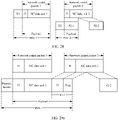
- the PDU may have the following four formats.
- the first field after the m th protocol subheader of the PDU is padded with a network coded unit of the m th network coded packet.
- the first field after the K th protocol subheader of the PDU is padded with a data part of the first network coded packet segment.
- the PDU generated by the transmit end device may be shown in FIG. 24 .
- the first field after the m th protocol subheader of the PDU is padded with the network coded unit of the m th network coded packet.
- the first field after the K th protocol subheader of the PDU is padded with the data part of the first network coded packet segment.
- the PDU further includes a (K+1) th protocol subheader.
- Information in the (K+1) th protocol subheader of the PDU is used to indicate one or more of the following: the quantity of network coded units included in the PDU, the size of the PDU, and the size of the field other than the protocol header in the PDU.
- the PDU generated by the transmit end device may be shown in FIG. 25 , where HT represents the (K+1) th protocol subheader of the PDU.
- the K protocol subheaders of the PDU are sequentially arranged to form the protocol header of the PDU.
- the PDU generated by the transmit end device may be shown in FIG. 26 .
- the K protocol subheaders of the PDU are arranged sequentially, and the PDU further includes the (K+1) th protocol subheader.
- Information in the (K+1) th protocol subheader is used to indicate one or more of the following: the quantity of network coded units included in the PDU, the size of the PDU, and the size of the field other than the protocol header in the PDU.
- the PDU generated by the transmit end device may be shown in FIG. 27 .
- the size of the generated PDU is greater than or equal to the size of the reference PDU.
- the size of the TB generated in step S502 is greater than or equal to the size of the reference TB.
- step S501 in a case in which the transmit end device compares the size of the reference SDU with the total size of the K network coded packets when obtaining the K network coded packets, that the transmit end device generates the PDU based on the first K-1 network coded packets and the first network coded packet segment may include: The transmit end device determines a payload based on the first K-1 network coded packets and the first network coded packet segment, and then the transmit end device generates the PDU based on the payload.
- An example is as follows.
- that the transmit end device generates the PDU based on the first K-1 network coded packets and the first network coded packet segment may include: The transmit end device uses the m th network coded packet in the first K-1 network coded packets as a payload of a m th PDU, and adds a protocol header of the m th PDU. The transmit end device uses the first network coded packet segment as a payload of a K th PDU, and adds a protocol header of the K th PDU. For example, based on the example shown in FIG. 21 , the PDU generated by the transmit end device may be shown in FIG. 28 , where HI is a protocol header of the first PDU, and H2 is a protocol header of the second PDU.
- that the transmit end device generates the PDU based on the first K-1 network coded packets and the first network coded packet segment may include: The transmit end device concatenates the first K-1 network coded packets and the first network coded packet segment to obtain the PDU.
- the first K-1 network coded packets and the first network coded packet segment are used as payloads of the PDU.
- the PDU includes a protocol header. Information in the protocol header is used to indicate one or more of the following: the quantity of network coded units included in the PDU, the size of the PDU, and the size of the field other than the protocol header in the PDU.
- the PDU generated by the transmit end device may be shown in FIG. 29a or FIG. 29b .
- a size of the payload determined by the transmit end device is greater than or equal to the size of the reference SDU.
- the size of the generated PDU is greater than or equal to the size of the reference PDU.
- the size of the TB generated in step S502 is greater than or equal to the size of the reference TB.
- the protocol header or the protocol subheader of the PDU may further include information used to indicate one or more of the following: the quantity of network coded units included in the PDU, the size of the PDU, and the size of the field other than the protocol header in the PDU.
- the foregoing method for generating a PDU is also applicable when the transmit end device generates the PDU based on the network coded packet and the network coded packet segment at a subsequent transmission opportunity.
- that the transmit end device outputs the TB in step S503 includes: The transmit end device sends the TB to the receive end device.
- Processing of the receive end device is similar to the foregoing processing method of the receive end device, where a difference is that the receive end performs segmenting and decoding based on the header information of the network coded packet and the segment header information of the network coded packet segment, and reference may be made to the foregoing related descriptions. Details are not described herein again.
- the transmit end device may further send request information to the receive end device.
- the request information is used to request first header information.
- the first header information includes header information of the second network coded packet and/or segment header information of a third network coded packet segment.
- the second network coded packet is one or more network coded packets in the K network coded packets.
- the third network coded packet segment is a segment of the last network coded packet in the K network coded packets.
- the receive end device may send the request information to the transmit end device, to request the transmit end device to retransmit the first header information.
- the transmit end device may send the first header information to the receive end device based on the request information.
- the transmit end device may retransmit the header information or the segment header information, without retransmitting a data part of the network coded packet or the network coded packet segment, to reduce resource overheads.
- the first protocol layer in this embodiment of this application may alternatively be the physical layer.
- the reference size is the size of the reference TB.
- Step S501 and step S502 may be combined into the following:
- the transmit end device generates the TB based on the reference size and the K network coded packets. In other words, the transmit end device does not generate the PDU, but generates the TB based on the reference size and the K network coded packets.
- a method for obtaining the reference size a method for obtaining the K network coded packets, and the like, refer to the foregoing related descriptions, and details are not described herein again.
- the methods and/or steps implemented by the transmit end device may be alternatively implemented by a component (for example, a chip or a circuit) that can be used in the transmit end device.
- the methods and/or steps implemented by the receive end device may be alternatively implemented by a component (for example, a chip or a circuit) that can be used in the receive end device.
- an embodiment of this application further provides a corresponding apparatus.
- the apparatus includes a corresponding module configured to perform the foregoing embodiments.
- the module may be software, hardware, or a combination of software and hardware.
- FIG. 30 is a schematic diagram of a structure of an apparatus.
- the apparatus 300 may be a terminal, or may be a chip, a chip system, a processor, or the like that supports the terminal in implementing the foregoing method.
- the apparatus 300 may be a network device, or may be a chip, a chip system, a processor, or the like that supports the network device in implementing the foregoing method.
- the apparatus 300 may be configured to implement the method described in the foregoing method embodiments. For details, refer to the descriptions in the foregoing method embodiments.
- the apparatus 300 may include one or more processors 3001.
- the processor 3001 may also be referred to as a processing unit, and can implement a specific control function.
- the processor 3001 may be a general-purpose processor, a dedicated processor, or the like.
- the processor 3001 may be a baseband processor or a central processing unit.
- the baseband processor may be configured to process a communication protocol and communication data.
- the central processing unit may be configured to: control a communication apparatus (for example, a base station, a baseband chip, a terminal, a terminal chip, a DU, or a CU), execute a software program, and process data of the software program.
- the processor 3001 may alternatively store instructions 3003, and the instructions 3003 may be run by the processor, so that the apparatus 300 performs the method described in the foregoing method embodiments.
- the processor 3001 may include a transceiver unit configured to implement receiving and sending functions.
- the transceiver unit may be a transceiver circuit, an interface, or an interface circuit.
- the transceiver circuit, the interface, or the interface circuit configured to implement the receiving and sending functions may be separated, or may be integrated together.
- the transceiver circuit, the interface, or the interface circuit may be configured to read and write code or data.
- the transceiver circuit, the interface, or the interface circuit may be configured to transmit or transfer a signal.
- the apparatus 300 may include a circuit, and the circuit may implement the sending, receiving, or communication function in the foregoing method embodiments.
- the apparatus 300 may include one or more memories 3002.
- the memory may store instructions 3004, and the instructions may be run on the processor, so that the apparatus 300 performs the method described in the foregoing method embodiments.
- the memory may further store data.
- the processor may also store instructions and/or data.
- the processor and the memory may be separately disposed, or may be integrated together. For example, the correspondence described in the foregoing method embodiments may be stored in the memory or stored in the processor.
- the apparatus 300 may further include a transceiver 3005 and/or an antenna 3006.
- the processor 3001 may be referred to as a processing unit, and controls the apparatus 300.
- the transceiver 3005 may be referred to as a transceiver unit, a transceiver machine, a transceiver circuit, a transceiver apparatus, a transceiver module, or the like, and is configured to implement sending and receiving functions.
- the apparatus 300 in this embodiment of this application may be configured to perform the method described in FIG. 5 in embodiments of this application.
- the processor and the transceiver that are described in this application may be implemented on an integrated circuit (integrated circuit, IC), an analog IC, a radio frequency integrated circuit RFIC, a hybrid signal IC, an application-specific integrated circuit (application-specific integrated circuit, ASIC), a printed circuit board (printed circuit board, PCB), an electronic device, or the like.
- integrated circuit integrated circuit, IC
- analog IC analog IC
- radio frequency integrated circuit RFIC radio frequency integrated circuit
- RFIC radio frequency integrated circuit
- hybrid signal IC an application-specific integrated circuit
- ASIC application-specific integrated circuit
- PCB printed circuit board
- an electronic device or the like.
- the processor and the transceiver may alternatively be manufactured by using various IC process technologies, for example, a complementary metal oxide semiconductor (complementary metal oxide semiconductor, CMOS), an nMetal-oxide-semiconductor (nMetal-oxide-semiconductor, NMOS), a positive channel metal oxide semiconductor (positive channel metal oxide semiconductor, PMOS), a bipolar junction transistor (Bipolar Junction Transistor, BJT), a bipolar CMOS (BiCMOS), silicon-germanium (SiGe), and gallium arsenide (GaAs).
- CMOS complementary metal oxide semiconductor
- NMOS nMetal-oxide-semiconductor
- NMOS nMetal-oxide-semiconductor
- PMOS positive channel metal oxide semiconductor
- BJT bipolar junction transistor
- BiCMOS bipolar CMOS
- SiGe silicon-germanium
- GaAs gallium arsenide
- the apparatus described in the foregoing embodiments may be a transmit end device (for example, a network device or a terminal).
- a scope of the apparatus described in this application is not limited thereto, and a structure of the apparatus may not be limited by FIG. 30 .
- the apparatus may be an independent device, or may be a part of a larger device.
- the apparatus may be:
- FIG. 31 is a schematic diagram of a structure of a terminal.
- the terminal is applicable to the scenarios shown in FIG. 2a to FIG. 3 .
- FIG. 31 shows only main components of the terminal.
- the terminal 310 includes a processor, a memory, a control circuit, an antenna, and an input/output apparatus.
- the processor is mainly configured to: process a communication protocol and communication data, control the entire terminal, execute a software program, and process data of the software program.
- the memory is mainly configured to store the software program and the data.
- a radio frequency circuit is mainly configured to perform conversion between a baseband signal and a radio frequency signal, and process the radio frequency signal.
- the antenna is mainly configured to receive and send the radio frequency signal in a form of an electromagnetic wave.
- the input/output apparatus for example, a touchscreen, a display, or a keyboard, is mainly configured to: receive data input by a user and output data to the user.
- the processor may read a software program in a storage unit, interpret and execute instructions of the software program, and process the data of the software program.
- the processor performs baseband processing on the to-be-sent data, and outputs a baseband signal to the radio frequency circuit.
- the radio frequency circuit processes the baseband signal to obtain a radio frequency signal, and the radio frequency circuit sends the radio frequency signal in a form of an electromagnetic wave through the antenna.
- the radio frequency circuit receives the radio frequency signal through the antenna, further converts the radio frequency signal into a baseband signal, and outputs the baseband signal to the processor.
- the processor converts the baseband signal into data, and processes the data.
- FIG. 31 shows only one memory and one processor.
- the terminal may have a plurality of processors and a plurality of memories.
- the memory may also be referred to as a storage medium, a storage device, or the like. This is not limited in embodiments of this application.
- the processor may include a baseband processor and a central processing unit.
- the baseband processor is mainly configured to process a communication protocol and communication data.
- the central processing unit is mainly configured to: control the entire terminal, execute the software program, and process the data of the software program.
- the processor in FIG. 31 integrates functions of the baseband processor and the central processing unit.
- the baseband processor and the central processing unit may alternatively be processors independent of each other, and are interconnected by using a technology such as a bus.
- the terminal may include a plurality of baseband processors to adapt to different network standards, and the terminal may include a plurality of central processing units to enhance a processing capability of the terminal.
- the baseband processor may also be expressed as a baseband processing circuit or a baseband processing chip.
- the central processing unit may also be expressed as a central processing circuit or a central processing chip.
- a function of processing the communication protocol and the communication data may be built in the processor, or may be stored in the storage unit in a form of the software program.
- the processor executes the software program, to implement a baseband processing function.
- the antenna and the control circuit that have a sending/receiving function may be considered as a transceiver unit 3111 of the terminal 310, and the processor having a processing function may be considered as a processing unit 3112 of the terminal 310.
- the terminal 310 includes the transceiver unit 3111 and the processing unit 3112.
- the transceiver unit may also be referred to as a transceiver, a transceiver machine, a transceiver apparatus, or the like.
- a component that is in the transceiver unit 3111 and that is configured to implement a receiving function may be considered as a receiving unit
- a component that is in the transceiver unit 3111 and that is configured to implement a sending function may be considered as a sending unit.
- the transceiver unit 3111 includes the receiving unit and the sending unit.
- the receiving unit may also be referred to as a receiver machine, a receiver, a receiver circuit, or the like.
- the sending unit may be referred to as a transmitter machine, a transmitter, a transmitter circuit, or the like.
- the receiving unit and the sending unit may be one integrated unit, or may be a plurality of independent units.
- the receiving unit and the sending unit may be in one geographical location, or may be distributed in a plurality of geographical locations.
- the apparatus may be a terminal, or may be a component (for example, an integrated circuit or a chip) of the terminal.
- the apparatus may be a network device, or may be a component (for example, an integrated circuit or a chip) of the network device.
- the apparatus may be another communication module configured to implement the method in the method embodiments of this application.
- the apparatus 320 may include a processing module 3202 (or referred to as a processing unit).
- the apparatus 320 may further include a transceiver module 3201 (or referred to as a transceiver unit) and a storage module 3203 (or referred to as a storage unit).
- one or more modules in FIG. 32 may be implemented by one or more processors, may be implemented by one or more processors and one or more memories, may be implemented by one or more processors and one or more transceivers, or may be implemented by one or more processors, one or more memories, and one or more transceivers.
- the processor, the memory, and the transceiver may be disposed separately, or may be integrated.
- the apparatus has a function of implementing the transmit end device described in embodiments of this application.
- the apparatus includes a corresponding module, unit, or means (means) used by the transmit end device to perform the steps related to the transmit end device and described in embodiments of this application.
- the function, the unit, or the means (means) may be implemented by software or hardware, may be implemented by hardware executing corresponding software, or may be implemented by a combination of software and hardware.
- the modules in the apparatus 320 in this embodiment of this application may be configured to perform the method described in FIG. 5 in embodiments of this application.
- the apparatus 320 may include the processing module 3202 and the transceiver module 3201.
- the processing module 3202 is configured to generate a PDU based on a reference size and K network coded packets.
- the processing module 3202 is further configured to generate a TB based on the PDU.
- the transceiver module 3201 is configured to output the TB.
- a transmit end device may generate the TB based on a size of a reference TB or a reference PDU, so that the TB can include an integer quantity of network coded packets. This reduces cases in which some bits of a network coded packet are correctly transmitted but decoding cannot be performed by using the bits because a coding coefficient of the network coded packet is not determined, and improves spectral efficiency.
- the processing module 3202 is specifically configured to obtain the K network coded packets based on the reference size, and generate the PDU based on the K network coded packets.
- the transmit end device may flexibly obtain the integer quantity of network coded packets based on the size of the reference TB or the reference PDU, so that data processing flexibility can be improved.
- the processing module 3202 is further specifically configured to segment the last network coded packet in the K network coded packets to obtain a plurality of network coded packet segments, and generate the PDU based on the first K-1 network coded packets and a first network coded packet segment in the K network coded packets.
- the first network coded packet segment includes header information of the last network coded packet.
- the first network coded packet segment includes the first N network coded packet segments in the plurality of network coded packet segments, where N is a positive integer.
- the transmit end device may include, in the first network coded packet segment, header information of a network coded packet to which the first network coded packet segment belongs. Therefore, the PDU generated by the transmit end device (for example, the apparatus 320) based on the first K-1 network coded packets and the first network coded packet segment includes the header information of the network coded packet to which the first network coded packet segment belongs, so that a receive end device can perform, based on the header information, decoding by using the first network coded packet segment. Therefore, spectral efficiency is improved.
- header information of a first network coded packet includes information used to indicate a coding coefficient of the last network coded packet.
- the first network coded packet is a network coded packet in the first K-1 network coded packets.
- the transmit end device may include, in the header information of the first network coded packet, the information used to indicate the coding coefficient of the last network coded packet.
- the receive end device can perform, based on the information used to indicate the coding coefficient of the last network coded packet, decoding by using a network coded packet segment other than the first network coded packet segment in the plurality of network coded packet segments. Therefore, spectral efficiency is improved.
- the processing module 3202 is further configured to add segment header information of a second network coded packet segment.
- the second network coded packet segment is a network coded packet segment other than the first network coded packet segment in the plurality of network coded packet segments.
- the segment header information includes the information used to indicate the coding coefficient of the last network coded packet.
- the transmit end device may add the segment header information of the second network coded packet segment.
- the receive end device can perform, based on the segment header information of the second network coded packet segment, decoding by using the second network coded packet segment. Therefore, spectral efficiency is improved.
- the segment header information further includes information used to indicate an identifier of a network coded block to which the last network coded packet belongs.
- the transmit end device may include, in the segment header information, the information of the identifier of the network coded block to which the last network coded packet belongs, so that the receive end device stores the network coded packet/segment based on the identifier of the network coded block, to facilitate subsequent decoding and reduce a processing delay.
- the transceiver module 3201 is further configured to receive a request message.
- the request information is used to request first header information.
- the first header information includes header information of a second network coded packet and/or segment header information of a third network coded packet segment.
- the second network coded packet is a network coded packet in the K network coded packets.
- the third network coded packet segment is a segment of the last network coded packet in the K network coded packets.
- the transceiver module 3201 is further configured to send, based on the request information, information used to indicate the first header information.
- the transmit end device when header information of a network coded packet or segment header information of a network coded packet segment is not correctly transmitted, the transmit end device (for example, the apparatus 320) retransmits the header information or the segment header information, without retransmitting a data part of the network coded packet or the network coded packet segment, to reduce resource overheads.
- a total size of the first K-1 network coded packets in the K network coded packets is less than the reference size, and a total size of the K network coded packets is greater than or equal to the reference size.
- a size of the PDU generated by the transmit end device may be greater than the size of the reference PDU, so that a code rate can be increased.
- the total size of the K network coded packets is less than or equal to the reference size, and a total size of the K network coded packets and a third network coded packet is greater than the reference size.
- the third network coded packet is a network coded packet other than the K network coded packets.
- the size of the PDU generated by the transmit end device may be less than the size of the reference PDU, so that the code rate can be reduced.
- a size of the TB is different from the size of the reference TB.
- the transmit end device (for example, the apparatus 320) does not need to generate the TB based on the size of the reference TB, so that data processing flexibility can be improved.
- the size of the PDU is different from the size of the reference PDU.
- the transmit end device (for example, the apparatus 320) does not need to generate the PDU based on the size of the reference PDU, so that data processing flexibility can be improved.
- the PDU is one of the following PDUs: a media access control MAC layer PDU, a radio link control RLC layer PDU, a backhaul adaptation protocol BAP layer PDU, a packet data convergence protocol PDCP layer PDU, or a PDU of a protocol layer having a network coding function.
- the processing module 3202 is further configured to determine, based on a PDU of a second protocol layer and with reference to a network coding parameter and/or a preset rule, a plurality of original data units included in a network coded block.
- the network coding parameter may include a size of the original data unit included in the network coded block and/or a quantity of original data units included in the network coded block.
- the preset rule may include: One PDU of the second protocol layer is used as one original data unit; or P PDUs of the second protocol layer are used as M original data units, where P is a positive integer, and M is a positive integer greater than or equal to 2.
- the processing module 3202 is specifically configured to: use a k th network coded packet in the K network coded packets as a k th PDU, where header information of the k th network coded packet is used as a protocol header of the k th PDU, and k is a positive integer from 1 to K; or use a k th network coded packet in the K network coded packets as a payload of a k th PDU, and add a protocol header of the k th PDU.
- the processing module 3202 is specifically configured to concatenate the K network coded packets to obtain the PDU.
- the PDU includes at least K protocol subheaders.
- the header information of the k th network coded packet in the K network coded packets is located in a k th protocol subheader of the PDU, where k is a positive integer from 1 to K.
- the first field after the k th protocol subheader of the PDU is padded with a network coded unit of the k th network coded packet.
- the K protocol subheaders of the PDU are sequentially arranged to form a protocol header of the PDU.
- the K protocol subheaders of the PDU are sequentially arranged, and the PDU further includes a (K+1) th protocol subheader.
- Information in the (K+1) th protocol subheader is used to indicate one or more of the following: a quantity of network coded units included in the PDU, a size of the PDU, and a size of a field other than the protocol header in the PDU.
- the processing module 3202 is specifically configured to concatenate the K network coded packets to obtain the PDU.
- the K network coded packets are used as payloads of the PDU.
- the PDU includes the protocol header.
- some optional features in embodiments of this application may be independently implemented without depending on another feature, for example, a solution on which the optional features are currently based, to resolve a corresponding technical problem and achieve a corresponding effect.
- the optional features are combined with other features based on requirements.
- an apparatus provided in embodiments of this application may also correspondingly implement these features or functions. Details are not described herein.
- the processor in embodiments of this application may be an integrated circuit chip, and has a signal processing capability.
- steps in the foregoing method embodiments can be implemented by using a hardware integrated logical circuit in the processor, or by using instructions in a form of software.
- the foregoing processor may be a general-purpose processor, a digital signal processor (digital signal processor, DSP), an application-specific integrated circuit (application-specific integrated circuit, ASIC), a field programmable gate array (field programmable gate array, FPGA) or another programmable logical device, a discrete gate or transistor logic device, or a discrete hardware component.
- a processing unit configured to perform these technologies at a communication apparatus (for example, a base station, a terminal, a network entity, or a chip) may be implemented in one or more general-purpose processors, a DSP, a digital signal processing device, an ASIC, a programmable logic device, an FPGA, or another programmable logic apparatus, a discrete gate or transistor logic device, a discrete hardware component, or any combination thereof.
- the general-purpose processor may be a microprocessor.
- the general-purpose processor may alternatively be any conventional processor, controller, microcontroller, or state machine.
- the processor may alternatively be implemented by a combination of computing apparatuses, such as a digital signal processor and a microprocessor, a plurality of microprocessors, one or more microprocessors in combination with a digital signal processor core, or any other similar configuration.
- the memory may be a transitory memory or a non-transitory memory, or may include both a transitory memory and a non-transitory memory.
- the non-transitory memory may be a read-only memory (read-only memory, ROM), a programmable read-only memory (programmable ROM, PROM), an erasable programmable read-only memory (erasable PROM, EPROM), an electrically erasable programmable read-only memory (electrically EPROM, EEPROM), or a flash memory.
- the transitory memory may be a random access memory (random access memory, RAM) and is used as an external cache.
- RAMs may be used, for example, a static random access memory (static RAM, SRAM), a dynamic random access memory (dynamic RAM, DRAM), a synchronous dynamic random access memory (synchronous DRAM, SDRAM), a double data rate synchronous dynamic random access memory (double data rate SDRAM, DDR SDRAM), an enhanced synchronous dynamic random access memory (enhanced SDRAM, ESDRAM), a synchlink dynamic random access memory (synchlink DRAM, SLDRAM), and a direct rambus dynamic random access memory (direct rambus RAM, DR RAM).
- static random access memory static random access memory
- DRAM dynamic random access memory
- DRAM dynamic random access memory
- SDRAM synchronous dynamic random access memory
- double data rate SDRAM double data rate SDRAM
- DDR SDRAM double data rate SDRAM
- ESDRAM enhanced synchronous dynamic random access memory
- synchlink dynamic random access memory synchlink dynamic random access memory
- direct rambus RAM direct rambus RAM
- This application further provides a computer-readable medium.
- the computer-readable medium stores a computer program.
- the computer program When the computer program is executed by a computer, functions of any one of the foregoing method embodiments are implemented.
- This application further provides a computer program product.
- the computer program product is executed by a computer, functions of any one of the foregoing method embodiments are implemented.
- All or some of the foregoing embodiments may be implemented by using software, hardware, firmware, or any combination thereof.
- software When software is used to implement embodiments, all or a part of embodiments may be implemented in a form of a computer program product.
- the computer program product includes one or more computer instructions. When the computer instructions are loaded and executed on the computer, the procedure or functions according to embodiments of this application are all or partially generated.
- the computer may be a general-purpose computer, a dedicated computer, a computer network, or another programmable apparatus.
- the computer instructions may be stored in a computer-readable storage medium or may be transmitted from a computer-readable storage medium to another computer-readable storage medium.
- the computer instructions may be transmitted from a website, computer, server, or data center to another website, computer, server, or data center in a wired (for example, a coaxial cable, an optical fiber, or a digital subscriber line (digital subscriber line, DSL)) or wireless (for example, infrared, radio, or microwave) manner.
- the computer-readable storage medium may be any usable medium accessible by the computer, or a data storage device, for example, a server or a data center, integrating one or more usable media.
- the usable medium may be a magnetic medium (for example, a floppy disk, a hard disk, or a magnetic tape), an optical medium (for example, a high-density digital video disc (digital video disc, DVD)), a semiconductor medium (for example, a solid-state drive (solid-state drive, SSD)), or the like.
- a magnetic medium for example, a floppy disk, a hard disk, or a magnetic tape
- an optical medium for example, a high-density digital video disc (digital video disc, DVD)
- a semiconductor medium for example, a solid-state drive (solid-state drive, SSD)
- an embodiment mentioned in the entire specification means that particular features, structures, or characteristics related to the embodiment are included in at least one embodiment of this application. Therefore, embodiments in the entire specification do not necessarily refer to a same embodiment. In addition, these particular features, structures, or characteristics may be combined in one or more embodiments by using any appropriate manner. It may be understood that sequence numbers of the foregoing processes do not mean an execution sequence in various embodiments of this application. The execution sequence of the processes should be determined based on functions and internal logic of the processes, and should not be construed as any limitation on the implementation processes of embodiments of this application.
- Simultaneously in this application may be understood as being at a same time point, may be understood as being within a time period, or may be understood as being within a same periodicity.
- first, second, and various reference numerals in this application are for distinguishing only for ease of description, and are not used to limit the scope of embodiments of this application.
- a specific value of a numeral (which may also be referred to as an index), a specific value of a quantity, and a position in this application are only used as an example, but are not unique representation forms, and are not used to limit the scope of embodiments of this application.
- First, second, and various reference numerals in this application are also for distinguishing only for ease of description, and are not used to limit the scope of embodiments of this application.
- an element represented in a singular form is intended to represent “one or more”, but is not intended to represent “one and only one”.
- "at least one” is intended to represent “one or more”
- "a plurality of' is intended to represent "two or more”.
- system and “network” may be used interchangeably in this specification.
- the term “and/or” in this specification describes only an association relationship for describing associated objects and represents that three relationships may exist.
- a and/or B may represent the following three cases: only A exists, both A and B exist, and only B exists.
- A may be singular or plural, and B may be singular or plural.
- the character “/” generally indicates an “or” relationship between the associated objects.
- At least one of' in this specification indicates all or any combination of listed items.
- “at least one of A, B, and C” may indicate the following six cases: Only A exists, only B exists, only C exists, both A and B exist, both B and C exist, and A, B and C all exist. A may be singular or plural, B may be singular or plural, and C may be singular or plural.
- B corresponding to A should indicate that B is associated with A, and B may be determined based on A. However, it should be further understood that determining B based on A does not mean that B is determined based only on A. B may alternatively be determined based on A and/or other information.
- the correspondences shown in the tables in this application may be configured, or may be predefined. Values of the information in the tables are only examples, and other values may be configured. This is not limited in this application. When a correspondence between information and each parameter is configured, not all correspondences shown in the tables need to be configured. For example, in the tables in this application, correspondences shown in some rows may alternatively not be configured. For another example, proper deformations and adjustments such as splitting and combination may be performed based on the foregoing tables. Names of the parameters shown in titles of the foregoing tables may alternatively be other names that can be understood by a communication apparatus, and values or representation manners of the parameters may alternatively be other values or representation manners that can be understood by the communication apparatus.
- another data structure such as an array, a queue, a container, a stack, a linear table, a pointer, a linked list, a tree, a graph, a structure, a class, a pile, or a hash table, may alternatively be used.
- Predefine in this application may be understood as “define”, “predefine”, “store”, “pre-store”, “pre-negotiate”, “pre-configure”, “solidify”, or “pre-burn”.
- the system, apparatus, and method described in this application may alternatively be implemented in another manner.
- the described apparatus embodiment is only an example.
- division into the units is only logical function division and may be other division in actual implementation.
- a plurality of units or components may be combined or integrated into another system, or some features may be ignored or not performed.
- the displayed or discussed mutual couplings or direct couplings or communication connections may be implemented through some interfaces.
- the indirect couplings or communication connections between the apparatuses or units may be implemented in electrical, mechanical, or another form.
- the units described as separate parts may or may not be physically separate, and parts displayed as units may or may not be physical units, may be located in one position, or may be distributed on a plurality of network units. Some or all of the units may be selected based on actual requirements to achieve the objectives of the solutions of embodiments.
- function units in embodiments of this application may be integrated into one processing unit, each of the units may exist alone physically, or two or more units may be integrated into one unit.
- the functions When the functions are implemented in the form of a software functional unit and sold or used as an independent product, the functions may be stored in a computer-readable storage medium.
- the computer software product is stored in a storage medium, and includes several instructions for instructing a computer device (which may be, for example, a personal computer, a server, or a network device) to perform all or some of the steps of the methods described in embodiments of this application.
- the foregoing storage medium includes any medium that can store program code, such as a USB flash drive, a removable hard disk, a read-only memory (read-only memory, ROM), a random access memory (random access memory, RAM), a magnetic disk, or an optical disc.
- program code such as a USB flash drive, a removable hard disk, a read-only memory (read-only memory, ROM), a random access memory (random access memory, RAM), a magnetic disk, or an optical disc.
Landscapes
- Engineering & Computer Science (AREA)
- Computer Networks & Wireless Communication (AREA)
- Signal Processing (AREA)
- Quality & Reliability (AREA)
- Mobile Radio Communication Systems (AREA)
- Data Exchanges In Wide-Area Networks (AREA)
Applications Claiming Priority (2)
| Application Number | Priority Date | Filing Date | Title |
|---|---|---|---|
| CN202010129066.6A CN113328826A (zh) | 2020-02-28 | 2020-02-28 | 数据处理方法及装置 |
| PCT/CN2020/137648 WO2021169522A1 (zh) | 2020-02-28 | 2020-12-18 | 数据处理方法及装置 |
Publications (2)
| Publication Number | Publication Date |
|---|---|
| EP4089936A1 true EP4089936A1 (de) | 2022-11-16 |
| EP4089936A4 EP4089936A4 (de) | 2023-09-27 |
Family
ID=77413370
Family Applications (1)
| Application Number | Title | Priority Date | Filing Date |
|---|---|---|---|
| EP20921222.4A Pending EP4089936A4 (de) | 2020-02-28 | 2020-12-18 | Datenverarbeitungsverfahren und -vorrichtung |
Country Status (4)
| Country | Link |
|---|---|
| US (1) | US12348309B2 (de) |
| EP (1) | EP4089936A4 (de) |
| CN (1) | CN113328826A (de) |
| WO (1) | WO2021169522A1 (de) |
Cited By (1)
| Publication number | Priority date | Publication date | Assignee | Title |
|---|---|---|---|---|
| US20240048496A1 (en) * | 2021-04-23 | 2024-02-08 | Fraunhofer-Gesellschaft zur Förderung der angewandten Forschung e.V. | Apparatus and method for the intrinsic analysis of the connection quality in radio networks having network-coded cooperation |
Families Citing this family (6)
| Publication number | Priority date | Publication date | Assignee | Title |
|---|---|---|---|---|
| CN115883005A (zh) * | 2021-09-26 | 2023-03-31 | 华为技术有限公司 | 数据传输方法、装置及可读存储介质 |
| CN116318524A (zh) * | 2021-12-21 | 2023-06-23 | 华为技术有限公司 | 一种数据编码方法及通信装置 |
| WO2023123336A1 (zh) * | 2021-12-31 | 2023-07-06 | Oppo广东移动通信有限公司 | 通信方法和设备 |
| US12323861B2 (en) * | 2022-03-09 | 2025-06-03 | Qualcomm Incorporated | RSU initiated inter-RSU handover |
| CN117318882A (zh) * | 2022-06-21 | 2023-12-29 | 华为技术有限公司 | 一种通信方法及装置 |
| CN122137495A (zh) * | 2024-12-02 | 2026-06-02 | 上海科邸斯科技有限公司 | 一种被用于无线通信的基于编码的传输方法和装置 |
Family Cites Families (9)
| Publication number | Priority date | Publication date | Assignee | Title |
|---|---|---|---|---|
| US6496520B1 (en) * | 2000-01-21 | 2002-12-17 | Broadcloud Communications, Inc. | Wireless network system and method |
| CN101621353B (zh) * | 2008-07-03 | 2013-08-07 | 华为技术有限公司 | 一种随机线性网络编码的方法、装置和系统 |
| US20130229968A1 (en) * | 2012-03-01 | 2013-09-05 | Telefonaktiebolaget L M Ericsson (Publ) | Network coding in a cellular communications system |
| US9185529B2 (en) * | 2013-03-15 | 2015-11-10 | Massachusetts Institute Of Technology | Wireless reliability architecture and methods using network coding |
| CN104753630A (zh) * | 2013-12-27 | 2015-07-01 | 中兴通讯股份有限公司 | 一种数据传输方法和系统 |
| US10034200B2 (en) * | 2015-10-23 | 2018-07-24 | Motorola Mobility Llc | Iteratively transmitting random linear network encoded packets from multiple transmission nodes |
| US20180359050A1 (en) * | 2015-11-25 | 2018-12-13 | Nokia Solutions And Networks Oy | Adaptive network coding in wireless communications |
| WO2017211417A1 (en) * | 2016-06-09 | 2017-12-14 | Nokia Solutions And Networks Oy | Real-time segmentation |
| CN107276727A (zh) * | 2017-05-04 | 2017-10-20 | 电信科学技术研究院 | 一种进行反馈的方法和设备 |
-
2020
- 2020-02-28 CN CN202010129066.6A patent/CN113328826A/zh active Pending
- 2020-12-18 EP EP20921222.4A patent/EP4089936A4/de active Pending
- 2020-12-18 WO PCT/CN2020/137648 patent/WO2021169522A1/zh not_active Ceased
-
2022
- 2022-08-26 US US17/896,145 patent/US12348309B2/en active Active
Cited By (1)
| Publication number | Priority date | Publication date | Assignee | Title |
|---|---|---|---|---|
| US20240048496A1 (en) * | 2021-04-23 | 2024-02-08 | Fraunhofer-Gesellschaft zur Förderung der angewandten Forschung e.V. | Apparatus and method for the intrinsic analysis of the connection quality in radio networks having network-coded cooperation |
Also Published As
| Publication number | Publication date |
|---|---|
| US20220416934A1 (en) | 2022-12-29 |
| US12348309B2 (en) | 2025-07-01 |
| CN113328826A (zh) | 2021-08-31 |
| WO2021169522A1 (zh) | 2021-09-02 |
| EP4089936A4 (de) | 2023-09-27 |
Similar Documents
| Publication | Publication Date | Title |
|---|---|---|
| US12348309B2 (en) | Data processing method and apparatus | |
| US12003322B2 (en) | Data transmission method and communication apparatus | |
| CN110621075B (zh) | 一种传输数据的方法和装置 | |
| US20240364464A1 (en) | Communication method and apparatus | |
| US12519515B2 (en) | Data processing method and apparatus | |
| EP4344293A1 (de) | Verfahren zum senden von daten, verfahren zum empfangen von daten und kommunikationsvorrichtung | |
| WO2024021982A1 (zh) | 通信方法及装置 | |
| US20250379705A1 (en) | Communication method and related apparatus | |
| US10469210B2 (en) | Acknowledgment data unit for data unit fragment | |
| EP4369757A1 (de) | Netzwerkcodierungsfunktionskonfigurationsverfahren und zugehörige vorrichtung | |
| US12335034B2 (en) | Coding method and apparatus | |
| US12494870B2 (en) | Communication method and apparatus | |
| WO2021013026A1 (zh) | 数据单元的发送方法、接收方法及装置 | |
| US20200145145A1 (en) | Acknowledgment data unit for data unit fragment | |
| EP3907911A1 (de) | Verfahren und vorrichtung zur drahtloskommunikation | |
| WO2024007292A1 (zh) | 发送数据和接收数据的方法以及通信装置 | |
| WO2022237673A1 (zh) | 一种处理数据的方法和装置 | |
| WO2018228553A1 (zh) | 数据传输的方法、网络设备和终端设备 | |
| CN113383591B (zh) | 一种通信方法及装置 | |
| CN110611554B (zh) | 反馈信息的传输方法和装置 | |
| WO2023016506A1 (zh) | 传输数据的方法及通信装置 | |
| WO2019095228A1 (en) | Method, apparatus and computer program | |
| EP4518209A2 (de) | Kommunikationsverfahren und -vorrichtung | |
| EP4539369A1 (de) | Kommunikationsverfahren und -vorrichtung | |
| CN121239359A (zh) | 通信方法和通信装置 |
Legal Events
| Date | Code | Title | Description |
|---|---|---|---|
| STAA | Information on the status of an ep patent application or granted ep patent |
Free format text: STATUS: THE INTERNATIONAL PUBLICATION HAS BEEN MADE |
|
| PUAI | Public reference made under article 153(3) epc to a published international application that has entered the european phase |
Free format text: ORIGINAL CODE: 0009012 |
|
| STAA | Information on the status of an ep patent application or granted ep patent |
Free format text: STATUS: REQUEST FOR EXAMINATION WAS MADE |
|
| 17P | Request for examination filed |
Effective date: 20220812 |
|
| AK | Designated contracting states |
Kind code of ref document: A1 Designated state(s): AL AT BE BG CH CY CZ DE DK EE ES FI FR GB GR HR HU IE IS IT LI LT LU LV MC MK MT NL NO PL PT RO RS SE SI SK SM TR |
|
| DAV | Request for validation of the european patent (deleted) | ||
| DAX | Request for extension of the european patent (deleted) | ||
| RIC1 | Information provided on ipc code assigned before grant |
Ipc: H04L 1/00 20060101AFI20230613BHEP |
|
| A4 | Supplementary search report drawn up and despatched |
Effective date: 20230824 |
|
| RIC1 | Information provided on ipc code assigned before grant |
Ipc: H04L 1/1867 20230101ALI20230818BHEP Ipc: H04L 1/00 20060101AFI20230818BHEP |
|
| STAA | Information on the status of an ep patent application or granted ep patent |
Free format text: STATUS: EXAMINATION IS IN PROGRESS |
|
| 17Q | First examination report despatched |
Effective date: 20250115 |