EP4090105A1 - Procédé de détermination de ressource de domaine temporel, dispositif et support - Google Patents
Procédé de détermination de ressource de domaine temporel, dispositif et support Download PDFInfo
- Publication number
- EP4090105A1 EP4090105A1 EP20912324.9A EP20912324A EP4090105A1 EP 4090105 A1 EP4090105 A1 EP 4090105A1 EP 20912324 A EP20912324 A EP 20912324A EP 4090105 A1 EP4090105 A1 EP 4090105A1
- Authority
- EP
- European Patent Office
- Prior art keywords
- discontinuous
- symbol
- time
- symbols
- occupied
- Prior art date
- Legal status (The legal status is an assumption and is not a legal conclusion. Google has not performed a legal analysis and makes no representation as to the accuracy of the status listed.)
- Granted
Links
Images




Classifications
-
- H—ELECTRICITY
- H04—ELECTRIC COMMUNICATION TECHNIQUE
- H04W—WIRELESS COMMUNICATION NETWORKS
- H04W72/00—Local resource management
- H04W72/04—Wireless resource allocation
- H04W72/044—Wireless resource allocation based on the type of the allocated resource
- H04W72/0446—Resources in time domain, e.g. slots or frames
-
- H—ELECTRICITY
- H04—ELECTRIC COMMUNICATION TECHNIQUE
- H04W—WIRELESS COMMUNICATION NETWORKS
- H04W72/00—Local resource management
- H04W72/20—Control channels or signalling for resource management
- H04W72/23—Control channels or signalling for resource management in the downlink direction of a wireless link, i.e. towards a terminal
-
- H—ELECTRICITY
- H04—ELECTRIC COMMUNICATION TECHNIQUE
- H04L—TRANSMISSION OF DIGITAL INFORMATION, e.g. TELEGRAPHIC COMMUNICATION
- H04L5/00—Arrangements affording multiple use of the transmission path
- H04L5/003—Arrangements for allocating sub-channels of the transmission path
- H04L5/0053—Allocation of signalling, i.e. of overhead other than pilot signals
-
- H—ELECTRICITY
- H04—ELECTRIC COMMUNICATION TECHNIQUE
- H04L—TRANSMISSION OF DIGITAL INFORMATION, e.g. TELEGRAPHIC COMMUNICATION
- H04L5/00—Arrangements affording multiple use of the transmission path
- H04L5/003—Arrangements for allocating sub-channels of the transmission path
- H04L5/0048—Allocation of pilot signals, i.e. of signals known to the receiver
-
- H—ELECTRICITY
- H04—ELECTRIC COMMUNICATION TECHNIQUE
- H04L—TRANSMISSION OF DIGITAL INFORMATION, e.g. TELEGRAPHIC COMMUNICATION
- H04L5/00—Arrangements affording multiple use of the transmission path
- H04L5/0091—Signalling for the administration of the divided path, e.g. signalling of configuration information
- H04L5/0094—Indication of how sub-channels of the path are allocated
-
- H—ELECTRICITY
- H04—ELECTRIC COMMUNICATION TECHNIQUE
- H04L—TRANSMISSION OF DIGITAL INFORMATION, e.g. TELEGRAPHIC COMMUNICATION
- H04L5/00—Arrangements affording multiple use of the transmission path
- H04L5/003—Arrangements for allocating sub-channels of the transmission path
- H04L5/0048—Allocation of pilot signals, i.e. of signals known to the receiver
- H04L5/005—Allocation of pilot signals, i.e. of signals known to the receiver of common pilots, i.e. pilots destined for multiple users or terminals
Definitions
- the present application relates to the field of wireless communications, and specifically to a method and device for determining a time-domain resource, and a medium.
- 4th-Generation (4G) Long-Term Evolution (LTE)/Long-Term Evolution Advanced (LTE-A), and 5th-Generation (5G) are facing more and more demands.
- Both 4G and 5G systems are developing toward enhanced mobile broadband, ultra-high reliability, ultra-low latency transmission, and massive connections.
- Short transmission time internal may be a single or several Orthogonal Frequency Division Multiplexing (OFDM) symbols.
- OFDM Orthogonal Frequency Division Multiplexing
- a Physical Downlink Control Channel is mainly used to carry scheduling information of downlink data transmission and scheduling information of uplink data transmission, notify a slot format, perform uplink power control, and so on.
- the resources include frequency-domain resources, i.e., resource blocks, and time-domain resources, i.e., time-domain symbols.
- NR New Radio
- LTE Long Term Evolution
- CRS cell-specific reference signal
- the present application provides a method and device for determining a time-domain resource and a medium, to ensure that the NR uses discontinuous time-domain symbols as time-domain resources for carrying a PDCCH in the case of coexistence of NR and LTE.
- an embodiment provides a method for determining a time-domain resource, which is applied to a base station.
- the method includes: obtaining a discontinuous CORESET signaling parameter in NR; and determining discontinuous time-domain symbols according to the discontinuous CORESET signaling parameter and transmitting the discontinuous time-domain symbols to a terminal, where the discontinuous time-domain symbols are used as time-domain resources for carrying a PDCCH.
- an embodiment provides a method for determining a time-domain resource, which is applied to a terminal.
- the method includes: obtaining discontinuous time-domain symbols determined by a base station side according to a discontinuous CORESET signaling parameter; and using the discontinuous time-domain symbols as time-domain resources for carrying a PDCCH.
- an embodiment provides a method for determining a time-domain resource, which is applied to a terminal.
- the method includes: obtaining a start position of a monitoring occasion and an occupied symbol value sent by a base station; obtaining a colliding symbol in response to a determination that a symbol collision occurs between NR and an LTE CRS; and determining discontinuous time-domain symbols according to the start position of the monitoring occasion, the occupied symbol value, and the colliding symbol, where the discontinuous time-domain symbols are time-domain resources for carrying a PDCCH.
- an embodiment provides a base station, including: one or more processors; and a memory, configured for storing one or more programs, where the one or more programs, when executed by the one or more processors, cause the one or more processors to perform the method provided in accordance with the first aspect of the present application.
- an embodiment provides a terminal, including: one or more processors; and a memory, configured for storing one or more programs, where the one or more programs, when executed by the one or more processors, cause the one or more processors to perform the method provided in accordance with the second aspect of the present application or the method provided in accordance with the third aspect of the present application.
- an embodiment provides a storage medium, storing a computer program which, when executed by a processor, causes the processor to perform any one of the methods provided in the embodiments of the present application.
- the NR can use discontinuous time-domain symbols as time-domain resources for carrying a PDCCH in the case of coexistence of NR and LTE.
- FIG. 1 is a flowchart of a method for determining a time-domain resource according to the present application.
- the method may be applied to a case where NR uses discontinuous time-domain symbols as time-domain resources for carrying a PDCCH.
- the method may be performed by a base station provided in the present application.
- the flowchart of the method for determining a time-domain resource according to the present application includes the following steps S101 to S102.
- the obtaining a discontinuous CORESET signaling parameter in NR includes: determining a time-domain symbol of an LTE frame structure occupied by a CRS on an antenna port; and generating the CORESET signaling parameter in NR according to the occupied time-domain symbol of the LTE frame structure.
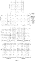
- FIG. 2 is a schematic diagram of an LTE CRS, and no PDCCH can be sent on a symbol where the LTE CRS is located. It may be determined from FIG. 2 that time-domain symbols of the LTE frame structure occupied by the CRS on a 1/2-antenna port are 0/4/7/11, time-domain symbols of the LTE frame structure occupied by the CRS ON a 4-antenna port are 0/1/4/7/8/11, and the CORESET signaling parameter in NR is generated according to the occupied time-domain symbols of the LTE frame structure.
- discontinuous time-domain symbols are determined according to the discontinuous CORESET signaling parameter and transmitted to a terminal.
- the discontinuous time-domain symbols are used as time-domain resources for carrying a PDCCH.
- the discontinuous CORESET signaling parameter includes: a start position of a monitoring occasion, and discontinuous symbols.
- the determining discontinuous time-domain symbols according to the discontinuous CORESET signaling parameter includes: determining a position of a start symbol of the discontinuous time-domain symbols in an NR frame structure according to the start position of the monitoring occasion; determining, according to the discontinuous symbols, symbol positions and a length of symbols that are occupied by the discontinuous time-domain symbols in the NR frame structure.
- the discontinuous CORESET signaling parameter includes: a start position of a monitoring occasion, an occupied symbol value, and discontinuous symbols.
- the determining discontinuous time-domain symbols according to the discontinuous CORESET signaling parameter includes: determining a position of a start symbol of the discontinuous time-domain symbols in an NR frame structure according to the start position of the monitoring occasion; determining, according to the occupied symbol value, a length of symbols occupied by the discontinuous time-domain symbols in the NR frame structure; and determining, according to the discontinuous symbols, symbol positions occupied by the discontinuous time-domain symbols in the NR frame structure.
- the discontinuous CORESET signaling parameter includes: a discontinuous symbol enable parameter, a discontinuous symbol determination parameter, and an occupied symbol value, where the discontinuous symbol enable parameter includes an enabled attribute or a disabled attribute.
- the determining discontinuous time-domain symbols according to the discontinuous CORESET signaling parameter includes: in a case where a determination is made that the discontinuous symbol enable parameter is of the enabled attribute, the discontinuous symbol determination parameter indicates a start position of a monitoring occasion and a specific position of an occupied symbol; determining, according to the discontinuous symbol determination parameter, a position of a start symbol of the discontinuous time-domain symbols in an NR frame structure and symbol positions occupied by the discontinuous time-domain symbols; and determining, according to the occupied symbol value, a length of symbols occupied by the discontinuous time-domain symbols in the NR frame structure.
- the discontinuous CORESET signaling parameter includes: a symbol colliding with the symbol occupied by the LTE CRS in NR, an offset, an occupied symbol value, and a start position of a monitoring occasion.
- the determining discontinuous time-domain symbols according to the discontinuous CORESET signaling parameter includes: determining a position of a start symbol of the discontinuous time-domain symbols in an NR frame structure according to the start position of the monitoring occasion; determining, according to the occupied symbol value, a length of symbols occupied by the discontinuous time-domain symbols in the NR frame structure; and determining, according to the offset, a number of symbols by which the discontinuous time-domain symbols are offset backward in a case that the colliding symbol is encountered.
- the discontinuous symbols are indicated by a bitmap or by a preset pattern.
- the method for determining the discontinuous time-domain symbols is described below with reference to difference cases respectively.
- the discontinuous CORESET signaling parameter includes a start position of a monitoring occasion and discontinuous symbols
- the start position of the monitoring occasion is represented by monitoringSymbolsWithinSlot
- the discontinuous symbols are represented by duration.
- FIG. 3 shows a schematic diagram of an LTE frame structure and an NR frame structure by taking 1/2 antenna ports as an example.
- the discontinuous symbol duration may be indicated by signaling BIT STRING (SIZE (14)), that is, indicated by a 14-bit bitmap, which may be set to 00110100000000.
- the start position monitoringSymbolsWithinSlot of the monitoring occasion may be set to 00100000000000.
- the start position of the monitoring occasion indicates that a start symbol of a PDCCH is 2, and the discontinuous symbols indicate that the occupied symbols are 2/3/5 and the length of symbols occupied is 3, thus avoiding symbol 4 which collides with LTE.
- the determined discontinuous time-domain symbols 2/3/5 are used as time-domain resources for carrying the PDCCH.
- the discontinuous symbols may be indicated by a 14-bit bitmap as described above, and may also be indicated by a preset pattern, for example, preset patterns of the discontinuous symbols shown in Table 1 to Table 4 below. Any rows in Table 1 to Table 4 may be combined, and the present application is not limited to the use of only three bits to indicate eight states, which, for example, may be extended to the use of four bits to indicate 16 symbol patterns or the use of five bits to indicate 32 symbol patterns.
- the discontinuous symbols may be in one of candidate preset patterns configured by Radio Resource Control (RRC).
- Preset Pattern1 may be represented by three bits 000.
- Pattern2 may be represented by three bits 001.
- Pattern3 may be represented by three bits 010.
- Pattern4 may be represented by three bits 011.
- Pattern5 may be represented by three bits 100.
- Pattern6 may be represented by three bits 101.
- Pattern7 may be represented by three bits 110.
- Pattern8 may be represented by three bits 111. Therefore, when a determination is made that the discontinuous symbols use Pattern4 in Table 1 represented by symbol 011, a further determination is made that the discontinuous symbols actually indicate 00110100000000, which can be represented by only three bits and does not need to occupy 14 bits.
- Such an indication method for the discontinuous symbols can reduce signaling overheads, thereby speeding up processing.
- the start position symbol of the monitoring occasion includes only one digit of 1, which indicates that the NR frame structure has one time-domain resource for carrying only one PDCCH.
- the start position symbol of the start position of the monitoring occasion includes multiple digits of 1, it means that there are multiple monitoring occasions, and the NR frame structure has time-domain symbols for carrying multiple PDCCHs.
- FIG. 4 shows a schematic diagram of an LTE frame structure and an NR frame structure carrying multiple PDCCHs by taking 1/2 antenna ports as an example.
- the discontinuous symbols duration may be indicated by signaling BIT STRING (SIZE (14)), and may be set to 01110110100000.
- the start position monitoringSymbolsWithinSlot of the monitoring occasion may be set to 01000100000000.
- symbols occupied by the first PDCCH monitoring occasion in a search space are 1/2/3, and the length of the symbols occupied is 3; symbols occupied by the second PDCCH monitoring occasion are 5/6/8, and the length of the symbols occupied is 3.
- the determined discontinuous time-domain symbols 1/2/3 and 5/6/8 are respectively used as time-domain resources for carrying the PDCCH.
- the PDCCH monitoring occasions may also occupy different symbol lengths.
- the start position monitoringSymbolsWithinSlot of the monitoring occasion may be set to 01000100000000, and the discontinuous symbols duration may be indicated by signaling BIT STRING (SIZE (14)), and may be set to 01100110100000.
- SIZE (14) signaling BIT STRING
- symbols occupied by the first PDCCH monitoring occasion in a search space are 1/2, and the length of the symbols occupied is 2; symbols occupied by the second PDCCH monitoring occasion are 5/6/8, and the length of the symbols occupied is 3.
- the determined discontinuous time-domain symbols 1/2 and 5/6/8 are respectively used as time-domain resources for carrying the PDCCH.
- FIG. 5 shows a schematic diagram of an LTE frame structure and an NR frame structure carrying multiple PDCCHs by taking four antenna ports as an example.
- the discontinuous symbols duration may be indicated by signaling BIT STRING (SIZE (14)), and may be set to 00110110011000, and the start position of the monitoring occasion may be set to 00100010000000.
- SIZE SIZE
- symbols occupied by the first PDCCH monitoring occasion in a search space are 2/3/5, and the length of the symbols occupied is 3; symbols occupied by the second PDCCH monitoring occasion are 6/9/10, and the length of the symbols occupied is 3.
- the determined discontinuous time-domain symbols 2/3/5 and 6/9/10 are respectively used as time-domain resources for carrying the PDCCH.
- the discontinuous CORESET signaling parameter includes a start position of a monitoring occasion, an occupied symbol value and discontinuous symbols
- the start position of the monitoring occasion is represented by monitoringSymbolsWithinSlot
- the occupied symbol value is represented by duration
- the discontinuous symbols are represented by location.
- FIG. 3 shows a schematic diagram of an LTE frame structure and an NR frame structure by taking 1/2 antenna ports as an example.
- the discontinuous symbols location may be indicated by signaling BIT STRING (SIZE (14)), that is, indicated by a 14-bit bitmap, which may be set to 00110100000000.
- the occupied symbol value duration may be set to 3.
- the start position of the monitoring occasion monitoringSymbolsWithinSlot may be set to 00100000000000.
- a determination may be made based on the information of the above three parameters that the occupied symbols indicated by the discontinuous symbols are 2/3/5 and the length of symbols occupied is 3, thus avoiding symbol 4 which collides with LTE.
- the determined discontinuous time-domain symbols 2/3/5 are used as time-domain resources for carrying the PDCCH. Difference from Case One, in Case Two, the discontinuous symbols are only used to indicate the position of the symbols occupied by the discontinuous time-domain symbol, and are not used to indicate the length of the occupied symbols.
- the discontinuous symbols may be indicated by a 14-bit bitmap as described above, and may also be indicated by a preset pattern, for example, the preset patterns of the discontinuous symbols shown in Table 1-Table 4 in Case One.
- information included in the discontinuous symbols specified by the preset patterns of the discontinuous symbols shown in Table 1 changes, i.e., is only used to indicate the position of the symbols occupied by the discontinuous time-domain symbols, and is not used to indicate the length of the occupied symbols.
- the start position symbol of the monitoring occasion includes only one digit of 1, which indicates that the NR frame structure has a time-domain resource for carrying only one PDCCH.
- the start position symbol of the start position of the monitoring occasion includes multiple digits of 1, it means that there are multiple monitoring occasions, and the NR frame structure has time-domain symbols for carrying multiple PDCCHs.
- FIG. 4 shows a schematic diagram of an LTE frame structure and an NR frame structure carrying multiple PDCCHs by taking 1/2 antenna ports as an example.
- the discontinuous symbols location may be indicated by signaling BIT STRING (SIZE (14)), and may be set to 01110110100000.
- the occupied symbol value duration may be set to 3.
- the start position monitoringSymbolsWithinSlot of the monitoring occasion may be set to 01000100000000. This means that symbols occupied by the first PDCCH monitoring occasion in a search space are 1/2/3, and the length of the symbols occupied is 3; symbols occupied by the second PDCCH monitoring occasion are 5/6/8, and the length of the symbols occupied is 3.
- the determined discontinuous time-domain symbols 1/2/3 and 5/6/8 are respectively used as time-domain resources for carrying the PDCCH.
- the discontinuous CORESET signaling parameter includes a discontinuous symbol enable parameter, a discontinuous symbol determination parameter and an occupied symbol value
- the discontinuous symbol enable parameter includes an enabled attribute or a disabled attribute
- the discontinuous symbol enable parameter is represented by a symbol discontinuous
- the discontinuous symbol determination parameter is represented by a symbol monitoringSymbolsWithinSlot
- the occupied symbol value is represented by duration.
- discontinuous symbol determination parameter monitoringSymbolsWithinSlot is not only used to indicate the start position of the PDCCH monitoring occasion, but is also used to indicate the specific position of the occupied symbols, to support the indication of discontinuous time-domain symbols.
- FIG. 4 shows a schematic diagram of an LTE frame structure and an NR frame structure carrying multiple PDCCHs by taking 1/2 antenna ports as an example.
- the discontinuous symbol determination parameter monitoringSymbolsWithinSlot may be set to 01110110100000.
- the occupied symbol value duration may be set to 3.
- the determined discontinuous time-domain symbols 1/2/3 and 5/6/8 are respectively used as time-domain resources for carrying the PDCCH.
- the discontinuous symbol determination parameter monitoringSymbolsWithinSlot can only be used to indicate the start position of the monitoring occasion, but cannot be used to indicate the specific position of the occupied symbols.
- the position of a start symbol of continuous time-domain symbols in an NR frame structure is determined according to the discontinuous symbol determination parameter monitoringSymbolsWithinSlot; and a length of symbols occupied by the continuous time-domain symbols in the NR frame structure is determined according to the occupied symbol value duration.
- the discontinuous CORESET signaling parameter includes a symbol colliding with the symbol occupied by the LTE CRS in NR, an offset, an occupied symbol value and a start position of a monitoring occasion
- the colliding symbol is represented by a symbol collidewithLTECRSsymbol
- the offset is represented by a symbol offsetOfcollidesymbol
- the occupied symbol value is represented by duration
- the start position of the monitoring occasion is represented by a symbol monitoringSymbolsWithinSlot.
- FIG. 3 shows a schematic diagram of an LTE frame structure and an NR frame structure by taking 1/2 antenna ports as an example.
- the colliding symbol collidewithLTECRSsymbol may be indicated by signaling BIT STRING (SIZE (14)), that is, indicated by a 14-bit bitmap, which may be set to 00010000000000, to indicate that symbol 4 collides with the symbol occupied by the LTE CRS.
- the offset offsetOfcollidesymbol may be indicated by signaling INTEGER(N), which indicates that the offset is set to N, where a maximum value of N is 13. In this embodiment, N may be set to 1.
- the occupied symbol value duration may be set to 3.
- the start position monitoringSymbolsWithinSlot of the monitoring occasion may be set to 00100000000000.
- a determination may be made according to the start position 00100000000000 of the monitoring occasion that the position of the starting symbol of the discontinuous time-domain symbols in the NR frame structure is symbol 2.
- a determination may be made according to the occupied symbol value duration that the symbol length occupied by the discontinuous time-domain symbols in the NR frame structure is 3, i.e., theoretically the discontinuous time-domain symbols should be 2/3/4 in a case that no collision occurs.
- a determination may be made according to the colliding symbol collidewithLTECRSsymbol that a collision occurs between NR and LTE CRS at symbol 4, and the discontinuous time-domain symbols need to be offset backward to ensure that the symbol length is 3.
- the above method may also use processing of offsetting backward by one symbol by default, and the base station does not need to notify the offset.
- the NR can use discontinuous time-domain symbols as time-domain resources for carrying a PDCCH in the case of coexistence of NR and LTE.
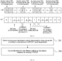
- FIG. 6 is a flowchart of a method for determining a time-domain resource according to the present application.
- the method may be applied to a case where NR uses discontinuous time-domain symbols as time-domain resources for carrying a PDCCH.
- the method may be performed by a terminal provided in the present application.
- the method may include S201 to S202.
- discontinuous time-domain symbols determined by a base station side are obtained according to a discontinuous CORESET signaling parameter.
- the base station side determines the discontinuous time-domain symbols 2/3/5 according to the discontinuous CORESET signaling parameter, and the terminal obtains the discontinuous time-domain symbols 2/3/5 determined by the base station side, for example, by wireless transmission.
- the specific type of transmission between the terminal side and the base station side is not limited in the embodiment, and any type of transmission falls within the scope of protection of the present application as long as the terminal side can obtain the discontinuous time-domain symbols sent by the base station side.
- the discontinuous time-domain symbols are used as time-domain resources for carrying a PDCCH.
- the terminal side After obtaining the discontinuous time-domain symbols 2/3/5 sent by the base station side, the terminal side uses the discontinuous time-domain symbols determined in the NR frame structure as time-domain resources for carrying the PDCCH, thereby solving the PDCCH coverage problem in the case of coexistence of NR and LTE.
- FIG. 7 is a flowchart of a method for determining a time-domain resource according to the present application.
- the method may be applied to a case where NR uses discontinuous time-domain symbols as time-domain resources for carrying a PDCCH.
- the method may be performed by a terminal provided in the present application.
- the flowchart of the method for determining a time-domain resource according to the present application includes the following steps S301 to S303.
- a start position of a monitoring occasion and an occupied symbol value sent by a base station are obtained.
- a terminal in NR may obtain a Decision Support System (DSS) working mode or other scenarios coexisting with LTE, and the terminal may know information about LTE transmit antenna ports.
- the terminal may obtain the start position and the occupied symbol value of the monitoring occasion that are sent by the base station, the start position of the monitoring occasion is represented by a symbol monitoringSymbolsWithinSlot, and the occupied symbol value is represented by duration.
- DSS Decision Support System
- FIG. 3 shows a schematic diagram of an LTE frame structure and an NR frame structure by taking 1/2 antenna ports as an example.
- the start position monitoringSymbolsWithinSlot of the monitoring occasion may be set to 00100000000000.
- the occupied symbol value duration may be set to 3.
- a colliding symbol is obtained in the case of determining that a symbol collision occurs between NR and an LTE CRS.
- the terminal may obtain that the current mode is the DSS working mode and the transmit antenna port number is 2, and therefore determine that a symbol colliding with the LTE CRS is symbol 4, and use the obtained symbol 4 as the colliding symbol.
- discontinuous time-domain symbols are determined according to the start position of the monitoring occasion, the occupied symbol value, and the colliding symbol,
- the discontinuous time-domain symbols are time-domain resources for carrying a PDCCH.
- the determining discontinuous time-domain symbols according to the start position of the monitoring occasion, the occupied symbol value and the colliding symbol includes: determining a position of a start symbol of the discontinuous time-domain symbols in an NR frame structure according to the start position of the monitoring occasion; determining, according to the occupied symbol value, a length of symbols occupied by the discontinuous time-domain symbols in the NR frame structure; and occupying a nearest available symbol following the colliding symbol until the occupied symbol value is satisfied, in the case of determining that the colliding symbol is encountered.
- a determination may be made according to the start position monitoringSymbolsWithinSlot of the monitoring occasion that the position of the starting symbol of the discontinuous time-domain symbols in the NR frame structure is symbol 2.
- a determination may be made according to the occupied symbol value duration that the length of symbols occupied by the discontinuous time-domain symbols in the NR frame structure is 3; and a determination is made that the colliding symbol is symbol 4.
- the determined discontinuous time-domain symbols are 2/3/5, and the determined discontinuous time-domain symbols 2/3/5 are used as time-domain resources for carrying the PDCCH.
- FIG. 8 is a schematic structural diagram of a base station according to the present application.
- the base station according to the present application includes: one or more processors 810 and a memory 820.
- the number of processors 810 in the base station may be one or more.
- FIG. 8 uses one processor 810 as an example.
- the memory 820 is configured for storing one or more programs. The one or more programs, when executed by the one or more processors 810, cause the one or more processors 810 to perform the method for determining a time-domain resource in the embodiments of the present invention.
- the processor 810 and the memory 820 in the base station may be connected by a bus or in other ways. Connection by a bus is used as an example in FIG. 8 .
- the memory 820 may be configured for storing software programs, computer-executable programs, and modules, for example, program instructions/modules corresponding to the method for determining a time-domain resource in the embodiments of the present application.
- the memory 820 may include a program storage area and a data storage area.
- the program storage area may store an operating system, and an application required by at least one function.
- the data storage area may store data created according to the use of the device and the like.
- the memory 820 may include a highspeed random access memory, and may also include a nonvolatile memory, e.g., at least one magnetic disk storage device, flash memory device, or other nonvolatile solid-state storage device.
- the memory 820 may further include memories located remotely from the processor 810. Examples of the network include, but not limited to, the Internet, an intranet, a local area network, a mobile communication network, and combinations thereof.
- FIG. 9 is a schematic structural diagram of a terminal according to the present application.
- the terminal according to the present application includes: one or more processors 910 and a memory 920.
- the number of processors 910 in the base station may be one or more.
- FIG. 9 uses one processor 910 as an example.
- the memory 920 is configured for storing one or more programs. The one or more programs, when executed by the one or more processors 910, cause the one or more processors 910 to perform the method for determining a time-domain resource in the embodiments of the present invention.
- the processor 910 and the memory 920 in the terminal may be connected by a bus or in other ways. Connection by a bus is used as an example in FIG. 9 .
- the memory 920 may be configured for storing software programs, computer-executable programs, and modules, for example, program instructions/modules corresponding to the method for determining a time-domain resource in the embodiments of the present application.
- the memory 920 may include a program storage area and a data storage area.
- the program storage area may store an operating system, and an application required by at least one function.
- the data storage area may store data created according to the use of the device and the like.
- the memory 920 may include a highspeed random access memory, and may also include a nonvolatile memory, e.g., at least one magnetic disk storage device, flash memory device, or other nonvolatile solid-state storage device.
- the memory 920 may further include memories located remotely from the processor 910. Examples of the network include, but not limited to, the Internet, an intranet, a local area network, a mobile communication network, and combinations thereof.
- An embodiment of the present application also provides a storage medium, storing a computer program.
- the computer program when executed by a processor, causes the processor to perform the method for determining a time-domain resource that is applied to a base station according to any one of the embodiments of the present application or the method for determining a time-domain resource that is applied to a terminal according to any one of the embodiments of the present application.
- the method for determining a time-domain resource that is applied to the base station includes: obtaining a discontinuous CORESET signaling parameter in NR; and determining discontinuous time-domain symbols according to the discontinuous CORESET signaling parameter and transmitting the discontinuous time-domain symbols to a terminal, where the discontinuous time-domain symbols are used as time-domain resources for carrying a PDCCH.
- the method for determining a time-domain resource that is applied to the terminal includes: obtaining discontinuous time-domain symbols determined by a base station side according to a discontinuous CORESET signaling parameter; and using the discontinuous time-domain symbols as time-domain resources for carrying a PDCCH.
- the method for determining a time-domain resource that is applied to the terminal includes: obtaining a start position of a monitoring occasion and an occupied symbol value sent by a base station; obtaining a colliding symbol in the case of determining that a symbol collision occurs between NR and an LTE CRS; and determining discontinuous time-domain symbols according to the start position of the monitoring occasion, the occupied symbol value and the colliding symbol, where the discontinuous time-domain symbols are time-domain resources for carrying a PDCCH.
- the term user terminal encompasses any suitable type of wireless user equipment, such as a mobile telephone, portable data processing device, portable web browser or vehicle-mounted mobile station.
- the various embodiments of the present application may be implemented in hardware or special purpose circuits, software, logic, or any combination thereof.
- some aspects may be implemented in hardware, while other aspects may be implemented in firmware or software that can be executed by a controller, microprocessor or other computing device, but the present application is not limited thereto.
- the embodiments of the present application may be implemented by the execution of computer program instructions by a data processor of a physical device, for example, in a processor entity, or by hardware, or by a combination of software and hardware.
- the computer program instructions may be assembly instructions, Instruction Set Architecture (ISA) instructions, machine instructions, machine dependent instructions, microcode, firmware instructions, state setting data, or source code or object code written in any combination of one or more programming languages.
- ISA Instruction Set Architecture
- the block diagram of any logic flow in the accompanying drawings of the present application may represent program steps, or may represent interconnected logic circuits, modules and functions, or may represent a combination of program steps and logic circuits, modules and functions.
- the computer program may be stored in a memory.
- the memory may be of any type suitable for the local technical environment and may be implemented using any suitable data storage technology, such as, but not limited to, Read-Only Memory (ROM), Random Access Memory (RAM), and optical storage devices and systems (Digital Video Disc (DVD) or Compact Disk (CD)), etc.
- the computer-readable medium may include a non-transitory storage medium.
- the data processor may be of any type suitable for the local technical environment, such as, but not limited to, a general purpose computer, a special purpose computer, a microprocessor, a Digital Signal Processor (DSP), an Application Specific Integrated Circuit (ASIC), a programmable logic device (Field-Programmable Gate Array (FPGA)), and a processor based on a multi-core processor architecture.
- a general purpose computer such as, but not limited to, a general purpose computer, a special purpose computer, a microprocessor, a Digital Signal Processor (DSP), an Application Specific Integrated Circuit (ASIC), a programmable logic device (Field-Programmable Gate Array (FPGA)), and a processor based on a multi-core processor architecture.
- DSP Digital Signal Processor
- ASIC Application Specific Integrated Circuit
- FPGA Field-Programmable Gate Array
Landscapes
- Engineering & Computer Science (AREA)
- Signal Processing (AREA)
- Computer Networks & Wireless Communication (AREA)
- Mobile Radio Communication Systems (AREA)
Applications Claiming Priority (2)
| Application Number | Priority Date | Filing Date | Title |
|---|---|---|---|
| CN202010026432.5A CN111901867B (zh) | 2020-01-10 | 2020-01-10 | 时域资源确定方法、设备及介质 |
| PCT/CN2020/141200 WO2021139576A1 (fr) | 2020-01-10 | 2020-12-30 | Procédé de détermination de ressource de domaine temporel, dispositif et support |
Publications (3)
| Publication Number | Publication Date |
|---|---|
| EP4090105A1 true EP4090105A1 (fr) | 2022-11-16 |
| EP4090105A4 EP4090105A4 (fr) | 2024-02-14 |
| EP4090105B1 EP4090105B1 (fr) | 2026-03-18 |
Family
ID=73169731
Family Applications (1)
| Application Number | Title | Priority Date | Filing Date |
|---|---|---|---|
| EP20912324.9A Active EP4090105B1 (fr) | 2020-01-10 | 2020-12-30 | Procédé de détermination de ressource de domaine temporel, dispositif et support |
Country Status (6)
| Country | Link |
|---|---|
| US (1) | US12542640B2 (fr) |
| EP (1) | EP4090105B1 (fr) |
| KR (1) | KR102943895B1 (fr) |
| CN (1) | CN111901867B (fr) |
| BR (1) | BR112022013049A2 (fr) |
| WO (1) | WO2021139576A1 (fr) |
Families Citing this family (4)
| Publication number | Priority date | Publication date | Assignee | Title |
|---|---|---|---|---|
| CN111901867B (zh) | 2020-01-10 | 2026-02-13 | 中兴通讯股份有限公司 | 时域资源确定方法、设备及介质 |
| CN115334661A (zh) * | 2021-05-11 | 2022-11-11 | 中兴通讯股份有限公司 | 通信方法、设备和存储介质 |
| JP7760079B2 (ja) * | 2022-04-29 | 2025-10-24 | 北京小米移動軟件有限公司 | 制御チャネル受信、送信方法と装置、通信装置及び記憶媒体 |
| CN115515242B (zh) * | 2022-09-21 | 2024-05-14 | 中国电信股份有限公司 | 搜索空间配置方法、物理下行控制信道搜索方法及装置 |
Family Cites Families (20)
| Publication number | Priority date | Publication date | Assignee | Title |
|---|---|---|---|---|
| CN102368759B (zh) * | 2011-11-04 | 2018-04-27 | 中兴通讯股份有限公司 | 下行控制信道的发送方法及装置 |
| US20170180095A1 (en) | 2015-12-22 | 2017-06-22 | Samsung Electronics Co., Ltd. | Method and apparatus for operating narrow bandwidth communications in wireless communication system |
| CN113411897A (zh) * | 2016-11-03 | 2021-09-17 | 华为技术有限公司 | 资源指示和上行控制信号传输的方法、装置 |
| CN108282875B (zh) * | 2017-01-06 | 2022-04-29 | 华为技术有限公司 | 一种数据收发方法及设备 |
| SG11201907185YA (en) * | 2017-02-03 | 2019-09-27 | Ntt Docomo Inc | User terminal and radio communication method |
| CN108633072B (zh) * | 2017-03-16 | 2022-08-26 | 株式会社Kt | 监视、发送和接收下行链路先占指示信息的方法及其装置 |
| CN108633052B (zh) * | 2017-03-24 | 2023-09-26 | 中兴通讯股份有限公司 | 一种资源配置方法、装置和设备 |
| CN108696463B (zh) * | 2017-04-06 | 2021-11-19 | 维沃软件技术有限公司 | 一种下行控制信道检测方法、终端及基站 |
| KR102458667B1 (ko) * | 2017-06-09 | 2022-10-25 | 삼성전자 주식회사 | 5세대 통신 시스템과 4세대 통신 시스템의 공존을 위한 방법 및 장치 |
| CN109391397B (zh) * | 2017-08-10 | 2021-08-27 | 中国电信股份有限公司 | 下行兼容传输方法、装置和计算机可读存储介质 |
| CN109391361B (zh) | 2017-08-11 | 2021-02-26 | 华为技术有限公司 | 检测下行控制信道的方法、终端设备和网络设备 |
| CN109691206A (zh) * | 2017-09-14 | 2019-04-26 | Oppo广东移动通信有限公司 | 用于传输信息的方法、终端设备和网络设备 |
| CN110035529B (zh) * | 2018-01-12 | 2021-07-16 | 华为技术有限公司 | 一种资源配置的方法和通信装置 |
| CN110149695B (zh) * | 2018-02-13 | 2021-04-09 | 维沃移动通信有限公司 | 确定寻呼消息位置的方法、通信设备、网络侧、用户设备 |
| CN110324109B (zh) | 2018-03-29 | 2021-11-26 | 北京紫光展锐通信技术有限公司 | Pdsch速率匹配方法、装置、用户终端及计算机可读存储介质 |
| WO2019194580A1 (fr) * | 2018-04-04 | 2019-10-10 | 엘지전자 주식회사 | Procédé de réception d'un signal de référence par un terminal dans un système de communications sans fil, et terminal utilisant le procédé |
| CN110351041B (zh) * | 2018-04-04 | 2022-01-28 | 中兴通讯股份有限公司 | 映射物理下行控制信道的方法及装置 |
| CN110611958B (zh) * | 2019-08-16 | 2026-04-17 | 中兴通讯股份有限公司 | 传输资源配置方法、装置和计算机存储介质 |
| EP4044721B1 (fr) * | 2019-11-08 | 2023-06-14 | Guangdong Oppo Mobile Telecommunications Corp., Ltd. | Procédé et appareil de détermination et de configuration d'un ensemble de ressources de commande |
| CN111901867B (zh) | 2020-01-10 | 2026-02-13 | 中兴通讯股份有限公司 | 时域资源确定方法、设备及介质 |
-
2020
- 2020-01-10 CN CN202010026432.5A patent/CN111901867B/zh active Active
- 2020-12-30 EP EP20912324.9A patent/EP4090105B1/fr active Active
- 2020-12-30 KR KR1020227021767A patent/KR102943895B1/ko active Active
- 2020-12-30 US US17/758,099 patent/US12542640B2/en active Active
- 2020-12-30 BR BR112022013049A patent/BR112022013049A2/pt unknown
- 2020-12-30 WO PCT/CN2020/141200 patent/WO2021139576A1/fr not_active Ceased
Also Published As
| Publication number | Publication date |
|---|---|
| US12542640B2 (en) | 2026-02-03 |
| EP4090105A4 (fr) | 2024-02-14 |
| US20220376872A1 (en) | 2022-11-24 |
| EP4090105B1 (fr) | 2026-03-18 |
| CN111901867B (zh) | 2026-02-13 |
| KR102943895B1 (ko) | 2026-03-26 |
| CN111901867A (zh) | 2020-11-06 |
| BR112022013049A2 (pt) | 2022-09-06 |
| WO2021139576A1 (fr) | 2021-07-15 |
| KR20220104812A (ko) | 2022-07-26 |
Similar Documents
| Publication | Publication Date | Title |
|---|---|---|
| CN110536449B (zh) | 无线通信资源指示方法、装置和系统 | |
| EP4090105B1 (fr) | Procédé de détermination de ressource de domaine temporel, dispositif et support | |
| US12507248B2 (en) | Wireless communication method and device | |
| EP4106427B1 (fr) | Procédé et appareil de transmission d'informations, dispositif associé et support de stockage | |
| AU2018401518B2 (en) | Transmission configuration method and related product | |
| WO2021155809A1 (fr) | Procédé et dispositif de transmission de signaux de synchronisation | |
| US20210378022A1 (en) | User equipment apparatus, base station, and random access method | |
| CN111757484B (zh) | 一种配置信息的方法与装置 | |
| EP3614756B1 (fr) | Procédés de communication sans fil, équipement terminal et noeuds d'émission et de réception | |
| WO2018128039A1 (fr) | Dispositif utilisateur et station de base | |
| JP2024528267A (ja) | M-trp pdcch反復のための異なるqcl-typedを有するコアセット選択 | |
| CN112534749B (zh) | 用于传输参考信号的方法及设备 | |
| JPWO2019064604A1 (ja) | 基地局及びユーザ装置 | |
| CN114342520A (zh) | 系统信息的传输方法和通信装置 | |
| CN111262675B (zh) | 一种确定dci格式的方法、终端设备和网络设备 | |
| KR102949842B1 (ko) | 향상된 랜덤 액세스 절차의 시스템 및 방법 | |
| WO2021088875A1 (fr) | Procédé et dispositif de transmission pour gc-pdcch | |
| WO2018201919A1 (fr) | Procédé et dispositif de transmission de données | |
| JP7600375B2 (ja) | アップリンク伝送を向上させるためのシステムおよび方法 | |
| EP4007386A1 (fr) | Terminal | |
| US20240121627A1 (en) | Information transmission method and communication apparatus | |
| CN113875304B (zh) | 参考信号的传输方法及装置 | |
| WO2025241573A1 (fr) | Procédé de détermination de transmission de signal répétée, appareil de communication, support de stockage et produit-programme | |
| HK40076427B (en) | Information transmission method and apparatus, related device, and storage medium | |
| HK40076427A (en) | Information transmission method and apparatus, related device, and storage medium |
Legal Events
| Date | Code | Title | Description |
|---|---|---|---|
| STAA | Information on the status of an ep patent application or granted ep patent |
Free format text: STATUS: THE INTERNATIONAL PUBLICATION HAS BEEN MADE |
|
| PUAI | Public reference made under article 153(3) epc to a published international application that has entered the european phase |
Free format text: ORIGINAL CODE: 0009012 |
|
| STAA | Information on the status of an ep patent application or granted ep patent |
Free format text: STATUS: REQUEST FOR EXAMINATION WAS MADE |
|
| 17P | Request for examination filed |
Effective date: 20220624 |
|
| AK | Designated contracting states |
Kind code of ref document: A1 Designated state(s): AL AT BE BG CH CY CZ DE DK EE ES FI FR GB GR HR HU IE IS IT LI LT LU LV MC MK MT NL NO PL PT RO RS SE SI SK SM TR |
|
| DAV | Request for validation of the european patent (deleted) | ||
| DAX | Request for extension of the european patent (deleted) | ||
| A4 | Supplementary search report drawn up and despatched |
Effective date: 20240116 |
|
| RIC1 | Information provided on ipc code assigned before grant |
Ipc: H04L 5/00 20060101ALI20240110BHEP Ipc: H04W 72/04 20090101AFI20240110BHEP |
|
| GRAP | Despatch of communication of intention to grant a patent |
Free format text: ORIGINAL CODE: EPIDOSNIGR1 |
|
| STAA | Information on the status of an ep patent application or granted ep patent |
Free format text: STATUS: GRANT OF PATENT IS INTENDED |
|
| INTG | Intention to grant announced |
Effective date: 20251202 |
|
| GRAS | Grant fee paid |
Free format text: ORIGINAL CODE: EPIDOSNIGR3 |
|
| GRAA | (expected) grant |
Free format text: ORIGINAL CODE: 0009210 |
|
| STAA | Information on the status of an ep patent application or granted ep patent |
Free format text: STATUS: THE PATENT HAS BEEN GRANTED |
|
| AK | Designated contracting states |
Kind code of ref document: B1 Designated state(s): AL AT BE BG CH CY CZ DE DK EE ES FI FR GB GR HR HU IE IS IT LI LT LU LV MC MK MT NL NO PL PT RO RS SE SI SK SM TR |
|
| REG | Reference to a national code |
Ref country code: CH Ref legal event code: F10 Free format text: ST27 STATUS EVENT CODE: U-0-0-F10-F00 (AS PROVIDED BY THE NATIONAL OFFICE) Effective date: 20260318 Ref country code: GB Ref legal event code: FG4D |
|
| REG | Reference to a national code |
Ref country code: IE Ref legal event code: FG4D |
|
| REG | Reference to a national code |
Ref country code: DE Ref legal event code: R096 Ref document number: 602020069017 Country of ref document: DE |