EP4090207B1 - Emulsifying tool and machinery for preparing food products comprising such a tool - Google Patents
Emulsifying tool and machinery for preparing food products comprising such a tool Download PDFInfo
- Publication number
- EP4090207B1 EP4090207B1 EP21703981.7A EP21703981A EP4090207B1 EP 4090207 B1 EP4090207 B1 EP 4090207B1 EP 21703981 A EP21703981 A EP 21703981A EP 4090207 B1 EP4090207 B1 EP 4090207B1
- Authority
- EP
- European Patent Office
- Prior art keywords
- support
- emulsifying
- emulsifying tool
- tool
- openings
- Prior art date
- Legal status (The legal status is an assumption and is not a legal conclusion. Google has not performed a legal analysis and makes no representation as to the accuracy of the status listed.)
- Active
Links
Images



Classifications
-
- A—HUMAN NECESSITIES
- A47—FURNITURE; DOMESTIC ARTICLES OR APPLIANCES; COFFEE MILLS; SPICE MILLS; SUCTION CLEANERS IN GENERAL
- A47J—KITCHEN EQUIPMENT; COFFEE MILLS; SPICE MILLS; APPARATUS FOR MAKING BEVERAGES
- A47J43/00—Implements for preparing or holding food, not provided for in other groups of this subclass
- A47J43/04—Machines for domestic use not covered elsewhere, e.g. for grinding, mixing, stirring, kneading, emulsifying, whipping or beating foodstuffs, e.g. power-driven
- A47J43/07—Parts or details, e.g. mixing tools, whipping tools
- A47J43/0716—Parts or details, e.g. mixing tools, whipping tools for machines with tools driven from the lower side
- A47J43/0722—Mixing, whipping or cutting tools
-
- B—PERFORMING OPERATIONS; TRANSPORTING
- B01—PHYSICAL OR CHEMICAL PROCESSES OR APPARATUS IN GENERAL
- B01F—MIXING, e.g. DISSOLVING, EMULSIFYING OR DISPERSING
- B01F23/00—Mixing according to the phases to be mixed, e.g. dispersing or emulsifying
- B01F23/40—Mixing liquids with liquids; Emulsifying
- B01F23/41—Emulsifying
-
- B—PERFORMING OPERATIONS; TRANSPORTING
- B01—PHYSICAL OR CHEMICAL PROCESSES OR APPARATUS IN GENERAL
- B01F—MIXING, e.g. DISSOLVING, EMULSIFYING OR DISPERSING
- B01F27/00—Mixers with rotary stirring devices in fixed receptacles; Kneaders
- B01F27/05—Stirrers
- B01F27/11—Stirrers characterised by the configuration of the stirrers
- B01F27/115—Stirrers characterised by the configuration of the stirrers comprising discs or disc-like elements essentially perpendicular to the stirrer shaft axis
- B01F27/1151—Stirrers characterised by the configuration of the stirrers comprising discs or disc-like elements essentially perpendicular to the stirrer shaft axis with holes on the surface
-
- B—PERFORMING OPERATIONS; TRANSPORTING
- B01—PHYSICAL OR CHEMICAL PROCESSES OR APPARATUS IN GENERAL
- B01F—MIXING, e.g. DISSOLVING, EMULSIFYING OR DISPERSING
- B01F27/00—Mixers with rotary stirring devices in fixed receptacles; Kneaders
- B01F27/05—Stirrers
- B01F27/11—Stirrers characterised by the configuration of the stirrers
- B01F27/115—Stirrers characterised by the configuration of the stirrers comprising discs or disc-like elements essentially perpendicular to the stirrer shaft axis
- B01F27/1152—Stirrers characterised by the configuration of the stirrers comprising discs or disc-like elements essentially perpendicular to the stirrer shaft axis with separate elements other than discs fixed on the discs, e.g. vanes fixed on the discs
-
- B—PERFORMING OPERATIONS; TRANSPORTING
- B01—PHYSICAL OR CHEMICAL PROCESSES OR APPARATUS IN GENERAL
- B01F—MIXING, e.g. DISSOLVING, EMULSIFYING OR DISPERSING
- B01F27/00—Mixers with rotary stirring devices in fixed receptacles; Kneaders
- B01F27/05—Stirrers
- B01F27/11—Stirrers characterised by the configuration of the stirrers
- B01F27/17—Stirrers with additional elements mounted on the stirrer, for purposes other than mixing
- B01F27/172—Stirrers with additional elements mounted on the stirrer, for purposes other than mixing for cutting, e.g. with knives
-
- B—PERFORMING OPERATIONS; TRANSPORTING
- B01—PHYSICAL OR CHEMICAL PROCESSES OR APPARATUS IN GENERAL
- B01F—MIXING, e.g. DISSOLVING, EMULSIFYING OR DISPERSING
- B01F27/00—Mixers with rotary stirring devices in fixed receptacles; Kneaders
- B01F27/80—Mixers with rotary stirring devices in fixed receptacles; Kneaders with stirrers rotating about a substantially vertical axis
- B01F27/808—Mixers with rotary stirring devices in fixed receptacles; Kneaders with stirrers rotating about a substantially vertical axis with stirrers driven from the bottom of the receptacle
Definitions
- the present invention relates to the field of machinery for preparing food products.
- the invention particularly relates to emulsifying tools.
- Document EP 2052772 describes a machine for dissolution which is also intended for food use, for example, in preparing food emulsions.
- a known example of a food emulsion is mayonnaise which is a stable emulsion of vegetable oil broken up in water with egg yolk as the emulsifier with the optional addition of vinegar or lemon juice which assist in stabilizing the emulsion itself.
- the machine described in EP 2052772 comprises a disk which is mounted on a rotating shaft inside a receptacle. On one or both faces of the disk there are welded shell-like or bowl-like elements which are suitable for breaking into small pieces the solid product which is contained in the receptacle and to dissolve it in a liquid phase.
- the shell-like or bowl-like shape of the cutting elements which have a specific type of asymmetrical form promotes the vertical circulation of the product and the consequent homogenization of the emulsion.
- the machine for dissolution described in EP 2053772 has various disadvantages, among which there may be noted the complexity of construction which involves a need to weld a number of bowl-like elements to the face of the rotating disk. In the event of one of the bowl-like elements breaking or becoming detached from the disk, it is necessary to replace the entire rotary dissolution group.
- Another disadvantage of the machine of EP 2053772 is the complexity of construction of the bowl-like elements which are necessary to obtain the vertical circulation of the product, for which it is necessary to use special tools and moulds.
- Another disadvantage is the need to distribute a number of bowl-like elements over the entire surface of the disk in order to be able to obtain a satisfactory dissolution.
- the dissolution machine described in EP 2053772 is complex and expensive to produce.
- this machine is constructed to perform only the function of dissolution and therefore is not generally used or appreciated in small-scale kitchens and food laboratories or where the preparation of emulsified products such as mayonnaise is only carried out sporadically or in small quantities.
- Another disadvantage of the machine of EP 2053772 which is particularly negative in the food sector, is the difficulty of keeping it clean, especially in the tight spaces between the disk and the external surface of the bowl-like elements, where there is the risk that deposits and encrustations of product may be formed.
- An object of the present invention is to overcome the disadvantages of the prior art by providing an emulsifying tool which can be efficiently used in machinery for preparing food products of the type indicated above.
- An object of the invention is particularly to provide an emulsifying tool, also referred to as a dissolving tool, which is simple and economic to manufacture.
- Another object of the invention is to construct an emulsifying tool which is easy to maintain and use.
- Another object is to provide an emulsifying tool which is easy to assemble on, and disassemble from a multipurpose machinery item for preparing food.
- Another object is to provide an emulsifying tool which is very easy and quick to clean after an emulsified product has been prepared.
- the invention further relates to a machinery item for preparing food products comprising such a tool.
- an emulsifying tool which is suitable for being used in machinery for preparing food products.
- the emulsifying tool is adapted to be mounted in an interchangeable manner on a drive shaft inside a process tank of the machinery item.
- the emulsifying tool comprises a support which can extend along a main plane, preferably a horizontal plane.
- the main plane defines two emulsion areas, one above and one below the emulsifying tool. During use, the two emulsion areas are occupied by the products to be emulsified and communicate with each other mainly through communication openings which are formed in the support.
- the products to be emulsified can therefore circulate from above and below the tool by mainly passing through the circulation openings in the support, even if it is not excluded that a portion of the product can circulate outside the tool, for example, by passing into the space between the tool and the side walls of the process tank.
- a movement transmission member can be positioned on the support in order to transmit a rotational movement thereto during use.
- the movement transmission member may be a central transmission member so as to transmit to the tool a rotational movement about a centre axis which is perpendicular to the above-mentioned main plane.
- There are provided in the emulsifying tool cutting members which can be mounted to be loose on the periphery of the support so as to oscillate with respect to the above-mentioned main plane. The oscillation of the cutting members promotes a rapid emulsion of the ingredients in the process tank and allows emulsified products to be obtained within far shorter times than are possible with the tools and machinery of the prior art.
- the support of the emulsifying tool is a disk which is particularly suitable for use in cylindrical process tanks.
- the communication openings formed in the support of the emulsifying tool are of circular form and are therefore simple to construct and do not have any angles for easier cleaning.
- the main openings are distributed angularly in an equidistant manner relative to each other over the support.
- the main openings are formed in the support near the periphery thereof. In other words, the main openings are at a greater distance from the centre of the support with respect to the distance thereof from the peripheral end of the support. In this manner, the support is less heavy in the zone in which the speed is greatest, reducing the moment of inertia.
- the main openings which are significant in the emulsion process have a greater efficiency because they operate at the maximum speed possible for the same angular rotation speed of the support.
- the emulsifying tool may comprise a plurality of secondary openings which have dimensions smaller than the main openings.
- the secondary openings can be distributed in an angularly non-uniform manner over the support.
- the secondary openings are arranged near the main openings.
- the non-uniform distribution of the secondary openings allows an emulsion which is not completely isotropic and homogeneous to be obtained because it introduces small random fluctuations into the product being processed.
- the resultant emulsified product is greatly appreciated with respect to a product which is produced with a precisely symmetrical tool probably because it makes the product more similar to a manual preparation.
- the cutting members may each comprise a plate element, that is to say, cutting members which are relatively wide and with a peripheral edge which is thinned.
- the plate elements have a flared shape, for example, a frustoconical, pyramidal or spherical cap-like shape, and the like.
- the shape of the plate element may define a planar base which can face away from the side opposite the support.
- the form of the plate may further define a peak zone which has smaller dimensions than the planar base. There may project from the peak zone a shank which is mounted with play in a hole in the support.
- the form of the plate element is simple to produce, easy to clean and quite resistant, particularly if the shank is produced to be integral with the flared member of the plate.
- the shank may be the shank of a screw inserted in the member of the plate in order to make the construction of the plate and the possible replacement thereof even simpler.
- the head of the screw may be countersunk in the planar base of the plate so as not to project therefrom.
- the head of the screw is flush with the planar base so as to promote the cleaning of the plate.
- a machinery item for preparing food products which comprises an emulsifying tool of the type described briefly above.
- the emulsifying tool may be part of a kit of interchangeable tools supplied with the machinery.
- the emulsifying tool may be inserted in a process tank of the machinery, and be connected, by means of the movement transmission member, to a drive shaft which projects from the base of the process tank.
- the support of the emulsifying tool is positioned in the process tank at such a height that the cutting members have small spacing from the base of the process tank.
- the machinery is capable of rapidly preparing without any effort any type of food product which involves an emulsion or dissolution of ingredients.
- the possibility of working at a pressure other than atmospheric pressure makes the use of the emulsifying tool described particularly efficient, promoting the rapid production of emulsions, such as mayonnaise, creams, sauces and other food preparations of the type, with a particularly appreciable flavour.
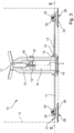
- an emulsifying tool 10 which is also referred to as a dissolving or dispersing tool.
- the emulsifying tool 10 is provided so as to be able to be used in known machinery for preparing food, for example, in the machine described in EP 1603437 .
- Such machinery generally comprises a process tank, for example, a cylindrical tank, which is indicated with the letter A in Figure 3 with a thin line.
- the process tank can be hermetically closed in order to produce a preparation chamber for food products.
- the machinery may comprise a heating system, by means of which it is possible to cook the food products.
- It may comprise a system for varying the pressure inside the process chamber, for example, in order to increase the pressure thereof or, conversely, to reduce it with respect to atmospheric pressure.
- Inside the process tank there can be mounted in an interchangeable manner processing tools, for example, for cutting, mixing or refining the ingredients and the food product being prepared.
- the tools are mounted on a drive shaft, which is indicated with the letter B in Figure 3 with a thin line and which projects from the base of the process tank and is rotatable about a centre axis Z.
- the emulsifying tool 10 comprises a support 11 which extends along a main plane which is indicated with the line X-X in Figure 3 and which is substantially horizontal in the preferred embodiment illustrated.
- the support 11 may be a disk, as illustrated, but could also be constructed in the form of a dial, ring or other suitable shapes.
- the support 11 is mounted, preferably with snap-fitting or coupling, on a metal tube 12 which is placed in a central position with respect to the support 11.
- the tooth 14 is configured in such a manner that during the step of locking the support 11 to the metal tube 12, it is inserted in a respective seat which is present in the outer perimeter of the projection 15.
- the tongue 13 is pressed downwards so that the projection 15 can rotate above the tooth 14 until the tooth itself, by moving into alignment with the seat thereof, can snap upwards into the same seat in order to thereby ensure the radial keying of the support 11 with respect to the metal tube 12.
- the vertical locking of the support 11 on the metal tube 12 is ensured by the two projections 15 which by rotating are arranged above corresponding shaped projections of the opening 16.
- the interior of the metal tube is hollow in order to be able to be inserted on the rotatable shaft B of the machinery.
- a nut screw 19 with a cross-member 18 fixed to the shaft of the metal tube.
- a screw 20 for adjusting the height of the metal tube 12, by means of which the introduction height of the metal tube 12 on the rotatable shaft B is adjusted and consequently also the height of the support 11 with respect to the base of the process tank A.
- a thumb screw 17 At the upper end of the metal tube 12 there is provided a thumb screw 17, by means of which it is possible to assemble and disassemble the emulsifying tool 10 on/from the rotatable shaft B.
- the support 11 extends so as to occupy virtually all the transverse area of the process tank A.
- extensive apertures 22 which, in the preferred though non-limiting form of the Figures, are circular, preferably with an equal extent.
- the apertures 22 are all arranged with the same spacing from the peripheral edge 21 and in particular the centres thereof are preferably located on the same concentric circumference with respect to the support 11.
- Small holes 23 which are distributed in an asymmetrical manner on the support 11 are formed near the apertures 22. In particular, as can be seen in the Figures, a single hole 23 is provided near a first aperture 22.
- a group of two adjacent holes 23 is provided near a second aperture 22 adjacent to the first aperture.
- a group of two holes 23 By moving sequentially in a counterclockwise direction in Figures 1 and 2 , near a third aperture 22 there is further formed a group of two holes 23, but which are spaced further apart from each other than the preceding group.
- a group of three holes 23 is formed near the fourth aperture 22.
- the holes 23 preferably all have the same dimensions, in particular the same diameter.
- the holes 23 are preferably arranged in a state grouped symmetrically with respect to the radius which extends through the centre of the aperture 22 nearest them. The presence of the holes 23 brings about asymmetry in the balancing of the support 11 and in the flow of product which passes through it during the rotation so as to promote an emulsion with a texture which is not too uniform and which has a flavour which is particularly appreciated.
- the elongate openings 24 are preferably constructed by being half-cut in such a manner that a portion of the material of the support 11 can be bent downwards in order to form wings 25 which promote the emulsion process by stirring the product near the central zone of the emulsifying tool 10.
- Movable plates 26 are mounted on the support 11.
- the movable plates 26 are preferably mounted in an alternating and equidistant manner from the apertures 22.
- the movable plates 26 have a member 27 with a generally flared shape, for example, a frustoconical shape as illustrated in the Figures, even though the possibility of constructing plates 26 with a pyramid shape or more rounded shape is not excluded, for example, in the form of a spherical cap.
- the base 28 of the movable plates 26 is directed towards the base of the process tank A, preferably with minimal spacing therefrom.
- a shank 30 with a threaded end projects from the peak 29 of the member 27 of the plate 26.
- the shank 30 is constructed to be integral with the member 27.
- the shank 30 is inserted with play inside a corresponding hole 32 in the support 11.
- the plate 26 is mounted to be loose on the support 11.
- the diameter of the shank is narrower than the hole 32 in the support 11 so that the shank 30 can slightly oscillate in the hole 32.
- the shank 30 is secured to the support 11 by means of an abutment fixed at the end thereof, for example, as a result of a nut 33 which is screwed to the threaded end thereof.
- the nut 33 is preferably a blind nut with the upper portion rounded in order to promote the cleaning of the emulsifying tool at the end of the preparation of a food product.
- the length of the shank 30 is such that the plate 28 is not tight against the face of the support 11 but instead remains slightly remote therefrom, for example, with a spacing of a few millimetres.
- the plates 26 are secured to the support 11 in a loose manner and have a given freedom of movement in a vertical direction, in terms of rotation and oscillation, vaguely resembling the metal disks of a tambourine. This freedom of movement is particularly effective for the purposes of separation of the molecules of the products inside the process tank A, thereby producing a particularly refined emulsion.
- the configuration of the plates 26 is such that they can swing in a state suspended on the plate 11, which makes them particularly easy to clean at the end of food preparation, simply by directing a jet of water onto them or by shaking them by oscillating the emulsifying tool inside the process tank A which is filled with water.
- the plates 26 are screwed to the support 11, it is possible to disassemble them and where applicable to replace them individually, thereby making both the ordinary handling and the unusual repair of the emulsifying tool 10 convenient, easy and economical.
- Figure 5 illustrates a variant of a movable plate for the support 11.
- the movable plate 36 has a geometry which is substantially similar to the one described above. More specifically, the movable plate 36 comprises a member 37 with a generally flared shape, for example, a frustoconical or pyramidal shape, or also with a more rounded shape, for example, in the form of a spherical cap.
- the base 38 of the member 37 of the movable plate 36 is also directed towards the base of the process tank A, that is to say, facing away from the side opposite the support 11.
- the base 38 projects over a portion from the peripheral edge of the support 11 in order to approach the internal side wall of the process tank A.
- the member 37 of the movable plate 36 has an axial hole 40, in which there is inserted a screw 41, the shank 42 of which projects from the peak 39 of the member 37.
- the shank 42 is inserted in the hole 32 in the support 11 which has a greater diameter so as to leave freedoms of oscillation and sliding for the plate 36.
- a nut 43 is screwed on the threaded end of the shank 42 for loosely connecting the plate 36 to the support 11.
- the screw 41 can be a stud bolt or, as illustrated in Figure 5 , a screw with a head 44 which in this case is preferably countersunk in a corresponding recess formed in the base 38 of the plate 36.
Landscapes
- Chemical & Material Sciences (AREA)
- Chemical Kinetics & Catalysis (AREA)
- Engineering & Computer Science (AREA)
- Mechanical Engineering (AREA)
- Food Science & Technology (AREA)
- Food-Manufacturing Devices (AREA)
- General Preparation And Processing Of Foods (AREA)
Applications Claiming Priority (2)
| Application Number | Priority Date | Filing Date | Title |
|---|---|---|---|
| IT202000000700 | 2020-01-16 | ||
| PCT/IB2021/050213 WO2021144703A1 (en) | 2020-01-16 | 2021-01-13 | Emulsifying tool and machinery for preparing food products comprising such a tool |
Publications (2)
| Publication Number | Publication Date |
|---|---|
| EP4090207A1 EP4090207A1 (en) | 2022-11-23 |
| EP4090207B1 true EP4090207B1 (en) | 2023-11-01 |
Family
ID=70295772
Family Applications (1)
| Application Number | Title | Priority Date | Filing Date |
|---|---|---|---|
| EP21703981.7A Active EP4090207B1 (en) | 2020-01-16 | 2021-01-13 | Emulsifying tool and machinery for preparing food products comprising such a tool |
Country Status (5)
| Country | Link |
|---|---|
| EP (1) | EP4090207B1 (da) |
| DK (1) | DK4090207T3 (da) |
| ES (1) | ES2969164T3 (da) |
| PL (1) | PL4090207T3 (da) |
| WO (1) | WO2021144703A1 (da) |
Family Cites Families (4)
| Publication number | Priority date | Publication date | Assignee | Title |
|---|---|---|---|---|
| DE102007051430B3 (de) * | 2007-10-25 | 2009-03-19 | Ak System Gmbh | Dissolver |
| US9301639B2 (en) * | 2014-03-04 | 2016-04-05 | Hsien-Ming Wang | Beverage foams making device |
| CN116078205A (zh) * | 2015-06-15 | 2023-05-09 | 维他拌管理有限公司 | 搅拌叶片 |
| CN106823883A (zh) * | 2017-03-14 | 2017-06-13 | 江苏奥能耐火材料有限公司 | 一种混料机用高速搅拌转子总成 |
-
2021
- 2021-01-13 PL PL21703981.7T patent/PL4090207T3/pl unknown
- 2021-01-13 WO PCT/IB2021/050213 patent/WO2021144703A1/en not_active Ceased
- 2021-01-13 DK DK21703981.7T patent/DK4090207T3/da active
- 2021-01-13 ES ES21703981T patent/ES2969164T3/es active Active
- 2021-01-13 EP EP21703981.7A patent/EP4090207B1/en active Active
Also Published As
| Publication number | Publication date |
|---|---|
| PL4090207T3 (pl) | 2024-06-10 |
| WO2021144703A1 (en) | 2021-07-22 |
| DK4090207T3 (da) | 2024-01-15 |
| ES2969164T3 (es) | 2024-05-16 |
| EP4090207A1 (en) | 2022-11-23 |
Similar Documents
| Publication | Publication Date | Title |
|---|---|---|
| MXPA06001472A (es) | Vaso de licuadora. | |
| EP3806647B1 (en) | Mixing device | |
| EP2201997B1 (en) | Beater for mixing | |
| EP3796784B1 (en) | Mixing device | |
| US4008882A (en) | Mixing unit for mixing and/or treating fluid materials | |
| CN103637710A (zh) | 基于食物的均化器 | |
| EP3422917B1 (en) | Helical beater member and beater system | |
| US5791779A (en) | Mixing assembly for continuous mixer | |
| EP4090207B1 (en) | Emulsifying tool and machinery for preparing food products comprising such a tool | |
| NO115922B (da) | ||
| SK132595A3 (en) | Stirring method of pumpable liquid | |
| JP3950877B2 (ja) | 食材の斜軸型ミキサー | |
| US3691938A (en) | Cooking apparatus | |
| US20190110494A1 (en) | Device and method for working on and processing chocolate as well as using a universal machine therefore | |
| CN101601980B (zh) | 液态纳米剪切机 | |
| JP7112718B2 (ja) | 撹拌装置 | |
| JP4359473B2 (ja) | 撹拌具及び撹拌具付撹拌装置 | |
| US2615690A (en) | Beater and bowl arrangement for mixers | |
| JP2021049234A (ja) | 食材用ミキサーの回転刃構造 | |
| RU2336011C2 (ru) | Взбивальный диск для кухонного прибора | |
| JP3149065B2 (ja) | 斜軸攪拌機 | |
| JP4990276B2 (ja) | 攪拌装置 | |
| CN215820624U (zh) | 用于炒锅的搅拌叶 | |
| EP0157915B1 (en) | Kneading machine | |
| CA2955126A1 (en) | A device for fixing and aligning cutter blades for a system for fine comminution |
Legal Events
| Date | Code | Title | Description |
|---|---|---|---|
| STAA | Information on the status of an ep patent application or granted ep patent |
Free format text: STATUS: UNKNOWN |
|
| STAA | Information on the status of an ep patent application or granted ep patent |
Free format text: STATUS: THE INTERNATIONAL PUBLICATION HAS BEEN MADE |
|
| PUAI | Public reference made under article 153(3) epc to a published international application that has entered the european phase |
Free format text: ORIGINAL CODE: 0009012 |
|
| STAA | Information on the status of an ep patent application or granted ep patent |
Free format text: STATUS: REQUEST FOR EXAMINATION WAS MADE |
|
| 17P | Request for examination filed |
Effective date: 20220708 |
|
| AK | Designated contracting states |
Kind code of ref document: A1 Designated state(s): AL AT BE BG CH CY CZ DE DK EE ES FI FR GB GR HR HU IE IS IT LI LT LU LV MC MK MT NL NO PL PT RO RS SE SI SK SM TR |
|
| DAV | Request for validation of the european patent (deleted) | ||
| DAX | Request for extension of the european patent (deleted) | ||
| REG | Reference to a national code |
Ref country code: DE Free format text: PREVIOUS MAIN CLASS: A47J0043070000 Ref legal event code: R079 Ref document number: 602021006447 Country of ref document: DE Ipc: B01F0023410000 |
|
| REG | Reference to a national code |
Ref country code: DE Ref legal event code: R079 Free format text: PREVIOUS MAIN CLASS: B01F0023410000 Ipc: A47J0043070000 Ref country code: DE Ref legal event code: R079 Ref document number: 602021006447 Country of ref document: DE Free format text: PREVIOUS MAIN CLASS: B01F0023410000 Ipc: A47J0043070000 |
|
| GRAP | Despatch of communication of intention to grant a patent |
Free format text: ORIGINAL CODE: EPIDOSNIGR1 |
|
| RIC1 | Information provided on ipc code assigned before grant |
Ipc: B01F 23/41 20220101AFI20230421BHEP |
|
| STAA | Information on the status of an ep patent application or granted ep patent |
Free format text: STATUS: GRANT OF PATENT IS INTENDED |
|
| RIC1 | Information provided on ipc code assigned before grant |
Ipc: A47J 43/07 20060101AFI20230505BHEP |
|
| INTG | Intention to grant announced |
Effective date: 20230601 |
|
| P01 | Opt-out of the competence of the unified patent court (upc) registered |
Effective date: 20230607 |
|
| GRAS | Grant fee paid |
Free format text: ORIGINAL CODE: EPIDOSNIGR3 |
|
| GRAA | (expected) grant |
Free format text: ORIGINAL CODE: 0009210 |
|
| STAA | Information on the status of an ep patent application or granted ep patent |
Free format text: STATUS: THE PATENT HAS BEEN GRANTED |
|
| AK | Designated contracting states |
Kind code of ref document: B1 Designated state(s): AL AT BE BG CH CY CZ DE DK EE ES FI FR GB GR HR HU IE IS IT LI LT LU LV MC MK MT NL NO PL PT RO RS SE SI SK SM TR |
|
| REG | Reference to a national code |
Ref country code: GB Ref legal event code: FG4D |
|
| REG | Reference to a national code |
Ref country code: CH Ref legal event code: EP |
|
| REG | Reference to a national code |
Ref country code: DE Ref legal event code: R096 Ref document number: 602021006447 Country of ref document: DE |
|
| REG | Reference to a national code |
Ref country code: IE Ref legal event code: FG4D |
|
| REG | Reference to a national code |
Ref country code: DK Ref legal event code: T3 Effective date: 20240108 |
|
| REG | Reference to a national code |
Ref country code: DE Ref legal event code: R081 Ref document number: 602021006447 Country of ref document: DE Owner name: MALAVASI, GIUSEPPE, IT Free format text: FORMER OWNER: MALAVASI, GIUSEPPE, SAN MARINO DI BENTIVOGLIO, BOLOGNA, IT |
|
| REG | Reference to a national code |
Ref country code: SE Ref legal event code: TRGR |
|
| REG | Reference to a national code |
Ref country code: CH Ref legal event code: PK Free format text: BERICHTIGUNGEN |
|
| REG | Reference to a national code |
Ref country code: NL Ref legal event code: FP |
|
| RAP4 | Party data changed (patent owner data changed or rights of a patent transferred) |
Owner name: MALAVASI, GIUSEPPE |
|
| RIN2 | Information on inventor provided after grant (corrected) |
Inventor name: MALAVASI, GIUSEPPE |
|
| REG | Reference to a national code |
Ref country code: LT Ref legal event code: MG9D |
|
| REG | Reference to a national code |
Ref country code: SK Ref legal event code: T3 Ref document number: E 43243 Country of ref document: SK |
|
| PG25 | Lapsed in a contracting state [announced via postgrant information from national office to epo] |
Ref country code: GR Free format text: LAPSE BECAUSE OF FAILURE TO SUBMIT A TRANSLATION OF THE DESCRIPTION OR TO PAY THE FEE WITHIN THE PRESCRIBED TIME-LIMIT Effective date: 20240202 |
|
| PG25 | Lapsed in a contracting state [announced via postgrant information from national office to epo] |
Ref country code: IS Free format text: LAPSE BECAUSE OF FAILURE TO SUBMIT A TRANSLATION OF THE DESCRIPTION OR TO PAY THE FEE WITHIN THE PRESCRIBED TIME-LIMIT Effective date: 20240301 |
|
| PG25 | Lapsed in a contracting state [announced via postgrant information from national office to epo] |
Ref country code: LT Free format text: LAPSE BECAUSE OF FAILURE TO SUBMIT A TRANSLATION OF THE DESCRIPTION OR TO PAY THE FEE WITHIN THE PRESCRIBED TIME-LIMIT Effective date: 20231101 |
|
| REG | Reference to a national code |
Ref country code: AT Ref legal event code: MK05 Ref document number: 1626223 Country of ref document: AT Kind code of ref document: T Effective date: 20231101 |
|
| PG25 | Lapsed in a contracting state [announced via postgrant information from national office to epo] |
Ref country code: AT Free format text: LAPSE BECAUSE OF FAILURE TO SUBMIT A TRANSLATION OF THE DESCRIPTION OR TO PAY THE FEE WITHIN THE PRESCRIBED TIME-LIMIT Effective date: 20231101 |
|
| PG25 | Lapsed in a contracting state [announced via postgrant information from national office to epo] |
Ref country code: LT Free format text: LAPSE BECAUSE OF FAILURE TO SUBMIT A TRANSLATION OF THE DESCRIPTION OR TO PAY THE FEE WITHIN THE PRESCRIBED TIME-LIMIT Effective date: 20231101 Ref country code: IS Free format text: LAPSE BECAUSE OF FAILURE TO SUBMIT A TRANSLATION OF THE DESCRIPTION OR TO PAY THE FEE WITHIN THE PRESCRIBED TIME-LIMIT Effective date: 20240301 Ref country code: GR Free format text: LAPSE BECAUSE OF FAILURE TO SUBMIT A TRANSLATION OF THE DESCRIPTION OR TO PAY THE FEE WITHIN THE PRESCRIBED TIME-LIMIT Effective date: 20240202 Ref country code: BG Free format text: LAPSE BECAUSE OF FAILURE TO SUBMIT A TRANSLATION OF THE DESCRIPTION OR TO PAY THE FEE WITHIN THE PRESCRIBED TIME-LIMIT Effective date: 20240201 Ref country code: AT Free format text: LAPSE BECAUSE OF FAILURE TO SUBMIT A TRANSLATION OF THE DESCRIPTION OR TO PAY THE FEE WITHIN THE PRESCRIBED TIME-LIMIT Effective date: 20231101 Ref country code: PT Free format text: LAPSE BECAUSE OF FAILURE TO SUBMIT A TRANSLATION OF THE DESCRIPTION OR TO PAY THE FEE WITHIN THE PRESCRIBED TIME-LIMIT Effective date: 20240301 |
|
| REG | Reference to a national code |
Ref country code: ES Ref legal event code: FG2A Ref document number: 2969164 Country of ref document: ES Kind code of ref document: T3 Effective date: 20240516 |
|
| PG25 | Lapsed in a contracting state [announced via postgrant information from national office to epo] |
Ref country code: RS Free format text: LAPSE BECAUSE OF FAILURE TO SUBMIT A TRANSLATION OF THE DESCRIPTION OR TO PAY THE FEE WITHIN THE PRESCRIBED TIME-LIMIT Effective date: 20231101 Ref country code: NO Free format text: LAPSE BECAUSE OF FAILURE TO SUBMIT A TRANSLATION OF THE DESCRIPTION OR TO PAY THE FEE WITHIN THE PRESCRIBED TIME-LIMIT Effective date: 20240201 Ref country code: LV Free format text: LAPSE BECAUSE OF FAILURE TO SUBMIT A TRANSLATION OF THE DESCRIPTION OR TO PAY THE FEE WITHIN THE PRESCRIBED TIME-LIMIT Effective date: 20231101 Ref country code: HR Free format text: LAPSE BECAUSE OF FAILURE TO SUBMIT A TRANSLATION OF THE DESCRIPTION OR TO PAY THE FEE WITHIN THE PRESCRIBED TIME-LIMIT Effective date: 20231101 |
|
| PG25 | Lapsed in a contracting state [announced via postgrant information from national office to epo] |
Ref country code: SM Free format text: LAPSE BECAUSE OF FAILURE TO SUBMIT A TRANSLATION OF THE DESCRIPTION OR TO PAY THE FEE WITHIN THE PRESCRIBED TIME-LIMIT Effective date: 20231101 Ref country code: EE Free format text: LAPSE BECAUSE OF FAILURE TO SUBMIT A TRANSLATION OF THE DESCRIPTION OR TO PAY THE FEE WITHIN THE PRESCRIBED TIME-LIMIT Effective date: 20231101 |
|
| REG | Reference to a national code |
Ref country code: DE Ref legal event code: R097 Ref document number: 602021006447 Country of ref document: DE |
|
| PG25 | Lapsed in a contracting state [announced via postgrant information from national office to epo] |
Ref country code: MC Free format text: LAPSE BECAUSE OF FAILURE TO SUBMIT A TRANSLATION OF THE DESCRIPTION OR TO PAY THE FEE WITHIN THE PRESCRIBED TIME-LIMIT Effective date: 20231101 |
|
| PG25 | Lapsed in a contracting state [announced via postgrant information from national office to epo] |
Ref country code: MC Free format text: LAPSE BECAUSE OF FAILURE TO SUBMIT A TRANSLATION OF THE DESCRIPTION OR TO PAY THE FEE WITHIN THE PRESCRIBED TIME-LIMIT Effective date: 20231101 |
|
| PLBE | No opposition filed within time limit |
Free format text: ORIGINAL CODE: 0009261 |
|
| STAA | Information on the status of an ep patent application or granted ep patent |
Free format text: STATUS: NO OPPOSITION FILED WITHIN TIME LIMIT |
|
| PG25 | Lapsed in a contracting state [announced via postgrant information from national office to epo] |
Ref country code: LU Free format text: LAPSE BECAUSE OF NON-PAYMENT OF DUE FEES Effective date: 20240113 |
|
| PG25 | Lapsed in a contracting state [announced via postgrant information from national office to epo] |
Ref country code: LU Free format text: LAPSE BECAUSE OF NON-PAYMENT OF DUE FEES Effective date: 20240113 |
|
| 26N | No opposition filed |
Effective date: 20240802 |
|
| PG25 | Lapsed in a contracting state [announced via postgrant information from national office to epo] |
Ref country code: SI Free format text: LAPSE BECAUSE OF FAILURE TO SUBMIT A TRANSLATION OF THE DESCRIPTION OR TO PAY THE FEE WITHIN THE PRESCRIBED TIME-LIMIT Effective date: 20231101 |
|
| PG25 | Lapsed in a contracting state [announced via postgrant information from national office to epo] |
Ref country code: SI Free format text: LAPSE BECAUSE OF FAILURE TO SUBMIT A TRANSLATION OF THE DESCRIPTION OR TO PAY THE FEE WITHIN THE PRESCRIBED TIME-LIMIT Effective date: 20231101 |
|
| PG25 | Lapsed in a contracting state [announced via postgrant information from national office to epo] |
Ref country code: RO Free format text: LAPSE BECAUSE OF FAILURE TO SUBMIT A TRANSLATION OF THE DESCRIPTION OR TO PAY THE FEE WITHIN THE PRESCRIBED TIME-LIMIT Effective date: 20231101 |
|
| PG25 | Lapsed in a contracting state [announced via postgrant information from national office to epo] |
Ref country code: CY Free format text: LAPSE BECAUSE OF FAILURE TO SUBMIT A TRANSLATION OF THE DESCRIPTION OR TO PAY THE FEE WITHIN THE PRESCRIBED TIME-LIMIT; INVALID AB INITIO Effective date: 20210113 |
|
| PG25 | Lapsed in a contracting state [announced via postgrant information from national office to epo] |
Ref country code: HU Free format text: LAPSE BECAUSE OF FAILURE TO SUBMIT A TRANSLATION OF THE DESCRIPTION OR TO PAY THE FEE WITHIN THE PRESCRIBED TIME-LIMIT; INVALID AB INITIO Effective date: 20210113 |
|
| PG25 | Lapsed in a contracting state [announced via postgrant information from national office to epo] |
Ref country code: FI Free format text: LAPSE BECAUSE OF FAILURE TO SUBMIT A TRANSLATION OF THE DESCRIPTION OR TO PAY THE FEE WITHIN THE PRESCRIBED TIME-LIMIT Effective date: 20231101 |
|
| REG | Reference to a national code |
Ref country code: CH Ref legal event code: U11 Free format text: ST27 STATUS EVENT CODE: U-0-0-U10-U11 (AS PROVIDED BY THE NATIONAL OFFICE) Effective date: 20260201 |
|
| PGFP | Annual fee paid to national office [announced via postgrant information from national office to epo] |
Ref country code: NL Payment date: 20260121 Year of fee payment: 6 |
|
| PGFP | Annual fee paid to national office [announced via postgrant information from national office to epo] |
Ref country code: SE Payment date: 20260121 Year of fee payment: 6 |
|
| PGFP | Annual fee paid to national office [announced via postgrant information from national office to epo] |
Ref country code: GB Payment date: 20260123 Year of fee payment: 6 |
|
| PGFP | Annual fee paid to national office [announced via postgrant information from national office to epo] |
Ref country code: ES Payment date: 20260227 Year of fee payment: 6 |
|
| PGFP | Annual fee paid to national office [announced via postgrant information from national office to epo] |
Ref country code: DK Payment date: 20260126 Year of fee payment: 6 Ref country code: IE Payment date: 20260122 Year of fee payment: 6 Ref country code: DE Payment date: 20260121 Year of fee payment: 6 |
|
| PGFP | Annual fee paid to national office [announced via postgrant information from national office to epo] |
Ref country code: BE Payment date: 20260121 Year of fee payment: 6 Ref country code: IT Payment date: 20260126 Year of fee payment: 6 |
|
| PGFP | Annual fee paid to national office [announced via postgrant information from national office to epo] |
Ref country code: FR Payment date: 20260123 Year of fee payment: 6 |
|
| PGFP | Annual fee paid to national office [announced via postgrant information from national office to epo] |
Ref country code: TR Payment date: 20260112 Year of fee payment: 6 |
|
| PGFP | Annual fee paid to national office [announced via postgrant information from national office to epo] |
Ref country code: CH Payment date: 20260201 Year of fee payment: 6 Ref country code: CZ Payment date: 20260112 Year of fee payment: 6 |
|
| PGFP | Annual fee paid to national office [announced via postgrant information from national office to epo] |
Ref country code: PL Payment date: 20260112 Year of fee payment: 6 |
|
| PGFP | Annual fee paid to national office [announced via postgrant information from national office to epo] |
Ref country code: SK Payment date: 20260112 Year of fee payment: 6 |