EP4090209B1 - Nettoyeur de sol - Google Patents
Nettoyeur de sol Download PDFInfo
- Publication number
- EP4090209B1 EP4090209B1 EP20845526.1A EP20845526A EP4090209B1 EP 4090209 B1 EP4090209 B1 EP 4090209B1 EP 20845526 A EP20845526 A EP 20845526A EP 4090209 B1 EP4090209 B1 EP 4090209B1
- Authority
- EP
- European Patent Office
- Prior art keywords
- agitator body
- brushroll
- deformable member
- cleaning head
- vane
- Prior art date
- Legal status (The legal status is an assumption and is not a legal conclusion. Google has not performed a legal analysis and makes no representation as to the accuracy of the status listed.)
- Active
Links
Images










Classifications
-
- A—HUMAN NECESSITIES
- A47—FURNITURE; DOMESTIC ARTICLES OR APPLIANCES; COFFEE MILLS; SPICE MILLS; SUCTION CLEANERS IN GENERAL
- A47L—DOMESTIC WASHING OR CLEANING; SUCTION CLEANERS IN GENERAL
- A47L9/00—Details or accessories of suction cleaners, e.g. mechanical means for controlling the suction or for effecting pulsating action; Storing devices specially adapted to suction cleaners or parts thereof; Carrying-vehicles specially adapted for suction cleaners
- A47L9/02—Nozzles
- A47L9/04—Nozzles with driven brushes or agitators
- A47L9/0461—Dust-loosening tools, e.g. agitators, brushes
- A47L9/0483—Reciprocating or oscillating tools, e.g. vibrators, agitators, beaters
-
- A—HUMAN NECESSITIES
- A46—BRUSHWARE
- A46B—BRUSHES
- A46B13/00—Brushes with driven brush bodies or carriers
- A46B13/001—Cylindrical or annular brush bodies
- A46B13/006—Cylindrical or annular brush bodies formed by winding a strip tuft in a helix about the body
-
- A—HUMAN NECESSITIES
- A46—BRUSHWARE
- A46B—BRUSHES
- A46B7/00—Bristle carriers arranged in the brush body
- A46B7/04—Bristle carriers arranged in the brush body interchangeably removable bristle carriers
-
- A—HUMAN NECESSITIES
- A46—BRUSHWARE
- A46B—BRUSHES
- A46B7/00—Bristle carriers arranged in the brush body
- A46B7/06—Bristle carriers arranged in the brush body movably during use, i.e. the normal brushing action causing movement
- A46B7/10—Bristle carriers arranged in the brush body movably during use, i.e. the normal brushing action causing movement as a rotating cylinder
-
- A—HUMAN NECESSITIES
- A46—BRUSHWARE
- A46B—BRUSHES
- A46B9/00—Arrangements of the bristles in the brush body
- A46B9/06—Arrangement of mixed bristles or tufts of bristles, e.g. wire, fibre, rubber
-
- A—HUMAN NECESSITIES
- A46—BRUSHWARE
- A46B—BRUSHES
- A46B9/00—Arrangements of the bristles in the brush body
- A46B9/08—Supports or guides for bristles
-
- A—HUMAN NECESSITIES
- A47—FURNITURE; DOMESTIC ARTICLES OR APPLIANCES; COFFEE MILLS; SPICE MILLS; SUCTION CLEANERS IN GENERAL
- A47L—DOMESTIC WASHING OR CLEANING; SUCTION CLEANERS IN GENERAL
- A47L5/00—Structural features of suction cleaners
- A47L5/12—Structural features of suction cleaners with power-driven air-pumps or air-compressors, e.g. driven by motor vehicle engine vacuum
- A47L5/22—Structural features of suction cleaners with power-driven air-pumps or air-compressors, e.g. driven by motor vehicle engine vacuum with rotary fans
- A47L5/28—Suction cleaners with handles and nozzles fixed on the casings, e.g. wheeled suction cleaners with steering handle
- A47L5/30—Suction cleaners with handles and nozzles fixed on the casings, e.g. wheeled suction cleaners with steering handle with driven dust-loosening tools, e.g. rotating brushes
-
- A—HUMAN NECESSITIES
- A47—FURNITURE; DOMESTIC ARTICLES OR APPLIANCES; COFFEE MILLS; SPICE MILLS; SUCTION CLEANERS IN GENERAL
- A47L—DOMESTIC WASHING OR CLEANING; SUCTION CLEANERS IN GENERAL
- A47L9/00—Details or accessories of suction cleaners, e.g. mechanical means for controlling the suction or for effecting pulsating action; Storing devices specially adapted to suction cleaners or parts thereof; Carrying-vehicles specially adapted for suction cleaners
- A47L9/02—Nozzles
- A47L9/04—Nozzles with driven brushes or agitators
- A47L9/0405—Driving means for the brushes or agitators
-
- A—HUMAN NECESSITIES
- A47—FURNITURE; DOMESTIC ARTICLES OR APPLIANCES; COFFEE MILLS; SPICE MILLS; SUCTION CLEANERS IN GENERAL
- A47L—DOMESTIC WASHING OR CLEANING; SUCTION CLEANERS IN GENERAL
- A47L9/00—Details or accessories of suction cleaners, e.g. mechanical means for controlling the suction or for effecting pulsating action; Storing devices specially adapted to suction cleaners or parts thereof; Carrying-vehicles specially adapted for suction cleaners
- A47L9/02—Nozzles
- A47L9/04—Nozzles with driven brushes or agitators
- A47L9/0455—Bearing means therefor
-
- A—HUMAN NECESSITIES
- A47—FURNITURE; DOMESTIC ARTICLES OR APPLIANCES; COFFEE MILLS; SPICE MILLS; SUCTION CLEANERS IN GENERAL
- A47L—DOMESTIC WASHING OR CLEANING; SUCTION CLEANERS IN GENERAL
- A47L9/00—Details or accessories of suction cleaners, e.g. mechanical means for controlling the suction or for effecting pulsating action; Storing devices specially adapted to suction cleaners or parts thereof; Carrying-vehicles specially adapted for suction cleaners
- A47L9/02—Nozzles
- A47L9/04—Nozzles with driven brushes or agitators
- A47L9/0461—Dust-loosening tools, e.g. agitators, brushes
- A47L9/0466—Rotating tools
- A47L9/0477—Rolls
-
- A—HUMAN NECESSITIES
- A46—BRUSHWARE
- A46B—BRUSHES
- A46B2200/00—Brushes characterized by their functions, uses or applications
- A46B2200/30—Brushes for cleaning or polishing
- A46B2200/302—Broom
Definitions
- the present invention relates to cleaning heads for floor cleaners.
- US 2,734,211 describes a rotary agitator construction in which the brush is inserted into a brush retaining channel in a cylindrical metal brush and agitator roll from the end of said roll and is retained in position by the bearing retaining and dust shielding structure.
- GB 2440282 describes an agitator assembly comprising a spindle having a first end, a second end, and a longitudinal axis. One or more primary agitators are attached to the spindle.
- a floor cleaner including a dirt collection chamber and a cleaning head in fluid communication with the dirt collection chamber.
- the cleaning head includes a housing, a brushroll chamber, and a brushroll.
- the brushroll chamber has an opening in a bottom side of the housing.
- the brushroll is operably mounted in the brushroll chamber.
- the brushroll includes an agitator body with a first end, a second end opposite the first end, and a longitudinal axis that extends through the first end and the second end.
- the agitator body is rotatable about the longitudinal axis and includes a first and a second concentric annular protrusion on the first end, extending along the longitudinal axis.
- the cleaning head further includes a bearing in rotatable communication with the first end of the agitator body.
- the end cap retains the bearing and is removable mounted to the housing, positioning the first end of the brushroll in the brushroll chamber.
- the end cap includes an outer side facing away from the agitator body and an inner side facing the first end of the agitator body.
- the inner side includes a first and a second concentric annular rib.
- the first and the second annular ribs and the first and the second annular protrusions overlap, so as to form a plurality of annular recesses between the adjacent annular ribs and the annular protrusions.
- An outermost annular recess is formed between the first annular rib and the first annular protrusion.
- the cleaning head includes a plurality of agitating members extending along the agitator body between the first end and the second end extend through the opening.
- a deformable member extends from the agitator body transverse to the longitudinal axis and is positioned along a circumference of the agitator body between the plurality of agitating members and the end cap.
- the deformable member is positioned adjacent the outermost annular recess and configured to inhibit debris from encountering the outermost annular recess.
- a cleaning head for a floor cleaner including a housing, a brushroll chamber, and a brushroll.
- the brushroll chamber has an opening in a bottom side of the housing.
- the brushroll is operably mounted in the brushroll chamber.
- the brushroll includes an agitator body extending between a first end and a second end opposite the first end.
- the agitator body includes a plurality of agitating members extending through the opening and configured to contact a surface to be cleaned.
- the agitating members include a vane extending longitudinally along the agitator body.
- the vane is connected to the agitator body along a first vane edge and a second vane edge such that the vane forms a loop extending outwardly from the agitator body.
- the vane includes a plurality of apertures along the longitudinal direction, aligning with a corresponding plurality of bristle holes in the agitator body under the loop.
- a row of bristles extending from the plurality of bristle holes in the agitator body through the corresponding plurality of apertures aligned therewith. The bristles are configured to contact the surface to be cleaned.
- a cleaning head for a floor cleaner comprising a housing, a brushroll chamber, a brushroll assembly.
- the brushroll assembly is mounted in the brushroll chamber.
- the brushroll assembly includes an agitator body and a cleaning member coupled to the agitator body between a first end and a second end.
- the cleaning member includes a plurality of cylindrical portions extending outwardly from the agitator body spaced in a longitudinally extending pattern along the agitator body. Each cylindrical portion is connected to the adjacent spaced cylindrical portion by a webbed portion. The webbed portion extends outwardly from the agitator body.
- the vane includes a plurality of bristle receptacles integrally molded along the longitudinal direction. A row of bristles are tufted into the bristle receptacles and extending outwardly from the loop, such that the row of bristles are configured to contact the surface to be cleaned.
- the disclosure relates to a brushroll assembly 20 for a floor cleaner, such as a vacuum cleaner, an extractor, or the like.
- Figs. 1 and 2 illustrate a floor cleaner 10.
- the floor cleaner 10 includes a cleaning head 12 having a housing 14, a brushroll chamber 16, and a longitudinal brushroll assembly 20.
- the brushroll assembly 20 is rotatably mounted within the housing 14 and configured to rotate about a bearing 28 located on at least one end thereof.
- the brushroll assembly 20 includes a deformable member 38 adjacent the bearing 28 configured to inhibit ingress of debris, hair, threads, and the like from entering the bearing 28.
- the deformable member 38 is an annular felt material.
- the brushroll chamber 16 includes an opening 18 in a bottom side of the housing 14.
- the brushroll assembly 20 is operably longitudinally mounted in the brushroll chamber 16 and extends through the opening 18 to contact a surface 50 to be cleaned.
- the brushroll assembly 20 includes an agitator body 22 that rotates relative to the housing 14 about a longitudinal axis 100.
- the longitudinal axis 100 extends through a first end 24 and a second send 26 of the agitator body 22.
- the bearing 28 facilitates rotation of the agitator body 22 about the longitudinal axis 100.
- the brushroll assembly 20 further includes an end cap 30 on one or both ends of the brushroll body 22 rotationally supporting and positioning the brushroll in the brushroll chamber 16.
- the cleaning head 12 may include an agitator drive mechanism in the housing 14.
- the brushroll body 22 includes one end cap 30 positioning the first end 24 of the brushroll in the brushroll chamber 16, and the drive mechanism includes a drive element 54 operably engaging the second end 26 of the agitator body 22, such as by a coaxial spline or gear drive engaging a splined recess 55 on the second end.
- the brushroll assembly 20 includes the end cap 30 on the first end 24 and on the second end 26 and the drive element 54 operably engages the brushroll body, such as by a gear or belt.
- the drive mechanism drives rotation of the agitator body 22 about the bearing 28 forming the longitudinal axis 100 shown in Fig. 3 .
- the bearing 28 may be operably mounted on the end cap 30.
- the agitator body 22 is rotatable to agitate, wipe, and clean the surface 50 to be being cleaned.
- the agitator body 22 includes a plurality of agitating members 32.
- the agitating members 32 include a plurality of vanes 34 and at least one row of bristles 36.
- the agitating members 32 extend between the first end 24 and the second end 26, and are spaced around the circumferential surface 47 of the agitator body 22, extending outwardly from the agitator body 22.
- the bristles 36 are shown schematically. Any suitable material may be used for the bristles, such as polymer bristles, fiber or rubber bristles, cloth strips or pads, beater bars, wipers, bristle strips, microfiber, and the like.
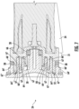
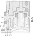
- the agitator body 22 extends along the longitudinal axis 100, with the end cap 30 received on the agitator body 22 to surround the bearing 28, and the deformable member 38 positioned around a circumferential surface of the agitator body 22.
- the deformable member 38 is in contacting engagement with at least one of the end cap 30 and the agitator body 22, however, the deformable member 38 may be in contacting engagement with both the end cap 30 and the agitator body 22.
- the deformable member 38 is positioned between the plurality of agitating members 32 and the end cap 30.
- the deformable member 38 extends radially outwardly from the agitator body 22 and is configured to inhibit the ingress of hair and debris into the bearing 28.
- the agitating members 32 extend from the agitator body a radial distance, and in one embodiment, the deformable member 38 extends beyond the radial distance of the agitating members 32. In one embodiment, the deformable member 38 extends through the opening 18 during operation to contact the surface 50 to be cleaned.
- the deformable member 38 may be composed of a felted material, tufted bristles, microfiber, felt, thermoplastic elastomeric, rubber, sponge, foam, nonwoven fabric, woven fabric, or a similar material.
- the deformable member 38 is compressible and configured to allow the brushroll assembly 20 to be removed out a lateral side 15 of the housing for cleaning and/or maintenance.
- the end cap 30 includes an outer side 53 facing away from the agitator body 22 and an inner side 51 facing the first end 24 of the agitator body.
- the outer side 53 forms a portion of an exterior surface 57 of the housing.
- the inner side 51 includes a plurality of concentric annular ribs facing the first end 24.
- the first end 24 of the agitator body includes a corresponding plurality of concentric annular protrusions 66 extending axially towards the end cap 30.
- first concentric annular protrusion 66' located radially outward of a second concentric annular protrusion 66".
- the first and the second annular ribs 64', 64" are configured to overlap the corresponding first and second annular protrusions 661, 66", so as to form a plurality of annular recesses 67 between the adjacent annular ribs and the annular protrusions.
- An outermost annular recess 67' is formed between the first annular rib 64' and the first annular protrusion 66'.
- the deformable member 38 is positioned adjacent the outermost annular recess 67' and configured to inhibit debris from encountering the outermost annular recess 67'.
- the deformable member 38 is an annular seal adjacent the first end 24 of the agitator body and adjacent the end cap 30, where the deformable member 38 is configured to inhibit debris from encountering the outermost annular recess 67' of the end cap.
- the deformable member 38 it is useful for the deformable member 38 to be received and retained between the plurality of agitating members 32 and the end cap 30.
- the circumferential surface 47 of the agitator body 22 includes a groove or depression 37 at the first end 24 between the plurality of agitating member 32 and the end cap 30. The groove 37 is configured to receive and retain the deformable member 38 during operation of the floor cleaner 10.
- the groove 37 inhibits the movement of the deformable member 38 during operation, specifically movement along the longitudinal axis 100 inward, away from the end cap 30.
- the deformable member 38 fits within the groove 37 such that the outer diameter of the deformable member 38 corresponds with the end cap 30.
- the deformable member 38 is attached to the agitator body in the groove 37 by friction fit, adhesive, press-fit, mechanical fasteners, or a similar mechanism.
- the deformable member 38 includes an interior region and an exterior region, the interior region having a first connecting member 43 that is coupled to a second connecting member 45 on the circumferential surface 47 of the agitator body 22, retaining the deformable member 38 on the agitator body 22 in operation.
- the interior region may be a rigid material and a deformable exterior region having a flexible elastomer coupled to the circumferential exterior forms the rest of the deformable member 38.
- the deformable exterior region may have a felt, foam, microfiber, or other deformable material coupled to the circumferential exterior to complete the deformable member 38.
- the brushroll assembly 20 further includes a second deformable member 38'.
- the second deformable member 38' extends from the agitator body 22 between the plurality of agitating members 32 and the drive element 54.
- the second deformable member 38' is configured to inhibit ingress of debris into the drive mechanism.
- the second deformable member 38' may be received and retained by a second groove 37' on the agitator body 22.
- the height of the second deformable member 38' extending outwardly from the agitator body 22 is greater than or equal to the height of the adjacent agitating member 32 extending outwardly from the agitating body 22, such that any hair or debris wrapped around the agitating member 32 is obstructed by the second deformable member 38' prior to reaching the drive mechanism.
- the hair or debris on the agitating member 32 exceeds the height of the second deformable member 38', the hair or debris then may enter the drive mechanism.
- the height of the deformable member 38 and the second deformable member 38' extending outwardly from the agitator body 22 is equal to or slightly less than the height of the adjacent agitating members 32.
- the deformable member 38 and second deformable member 38' act as a first defense to inhibit hair and debris reaching the bearing 28 and the drive mechanism, respectively.
- a labyrinth seal 52 arrangement defined in the relationship between overlapping relationship of the annular ribs 64 of the end cap and the annular protrusions 66 of the agitator body.
- the labyrinth seal 52 creates a tortuous path to inhibit hair and debris that overcomes the deformable member 38 from entering the bearing 28 through the outermost annular recess 67'.
- the plurality of annular recesses 67 create space, making the path more difficult for hair and debris to reach the bearing 28.
- the labyrinth seal 52 arrangement between the end cap 30 and the agitator body 22 inhibits hair and debris from entering the bearing 28 or the drive element 54.
- the agitator body 22 extends between the first end 24 and the second end 26 opposite the first end 24.
- the agitating members 32 rotate along with the agitator body 22, contacting the surface 50 through the opening 18 and facilitating surface debris pick-up.
- the agitator members 32 are configured to improve surface debris pick-up and reduce brushroll maintenance by inhibiting hair and debris wrap around the brushroll.
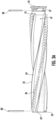
- the agitating members 32 include only a plurality of vanes 34.
- the plurality of vanes 34 inhibit hair wrap, in part, by increasing the circumference of the agitator body 22, and preventing hair and debris below a predetermined length from wrapping fully around the agitator body 22.
- the solid nature of the vanes 34 from the first end 24 to the second end 26 create a surface that is more difficult for hair to wrap around when compared to tufted bristles with gaps between adjacent tufts.
- the vanes 34 can be made of rubber, nylon, vinyl, thermoplastic elastomer, nonwoven fabric, woven fabric, among other materials. The flexibility of the vanes 34 allows bending and flexing during operation, which further reduces debris wrap around the agitator body 22 by not allowing the hair and debris a stationary portion to wrap around.
- the plurality of vanes 34 have a first vane end 31 adjacent the first end 24 and a second vane end 33 adjacent the second end 26.
- the vanes 34 include a surface engaging portion 35 longitudinally extending along the agitator body 22 between the first vane end 31 and the second vane end 33.
- the surface engaging portion 35 promotes surface debris pick-up and inhibits hair and debris wrap around the agitator body 22.
- the deformable member 38 is positioned between the first vane end 31 and the end cap 30 to inhibit debris from encountering the end cap 30.
- the second deformable member 38' is positioned between the second vane end 33 and the drive element 54 to inhibit debris from encountering the drive element 54.
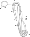
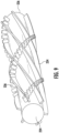
- the plurality of agitating members 32 wrap around the agitator body 22 between the first end 24 and the second end 26 in a helical pattern.
- the helical pattern can be defined by a single helix, such that all of the agitating members 32 lie in a single, common helix with respect to the longitudinal axis 100.
- the agitating members 32 may be a plurality of vanes 34 and bristles 36 that have the same helical pattern around the brushroll assembly 20, however each having a different starting point.
- the congruent helical pattern of the agitating members 32 helps provide even and consistent debris pick-up, while inhibiting hair and debris wrap around the brushroll 20.
- the helical pattern of the plurality of vanes and the helical pattern of the bristles extend around the agitator body in opposite directions.
- the plurality of vanes 234 wrap helically approximately 180 degrees around the agitator body between the first end 224 and the second end 226 in a first direction, while the bristles 236 wrap helically approximately 360 degrees around the agitator body in a second direction, opposite the first direction.
- the plurality of vanes 234 wrap helically between approximately 200 degrees and 400 degrees around the agitator body in the first direction, while the bristles 236 wrap helically approximately 360 degrees to 720 degrees in the second direction.
- a greater difference between the opposing helical patterns i.e. where the opposing helical patterns have higher rotations about the agitator body, results in a greater intersection angle where the vanes 234 and the bristles cross 236.
- a greater intersection angle can be advantageous because it results in less bristles being removed due to interference with the vanes.
- the vanes 34 define a constant helical pattern about the agitator body 22 from the first end 24 to the second end 26, and the one or more rows of bristles 36 define an oscillating or variable pattern about the agitator body 22 from the first end 24 to the second end 26.
- the oscillating pattern of the bristles 36 extends between two adjacent vanes 34. This oscillating pattern allows for a variable distance between the row of bristles 36 and the adjacent vanes 34, which can result in improved cleaning and reduced wrapping of hair and debris around the agitator body 22. Further, it has been found that hair and debris wrap is most prevalent in the space between adjacent tufted bristles. Having bristles with an oscillating pattern creates a more angled path for hair and debris to get embedded in the space between adjacent bristles, thus making for a more difficult path and reducing hair and debris wrap around the agitator body 22.
- an agitator body 322 has two or more cleaning members 332 extending between a first end 324 and a second end 326 of the agitator body 322.
- the cleaning members 332 includes a plurality of spaced cylindrical portions 336 between the first end 324 and the second end 326 that are connected by a webbed portion 334.
- the spaced cylindrical portions 336 provide agitation to the surface 50 to be cleaned to enhance debris pick-up, while the webbed portion 334 inhibits hair, threads, and debris from becoming wrapped between the cylindrical portions 336, and around the agitator body 322.
- the cleaning members 332 may be elastomeric, vinyl, or any suitable material. This arrangement has been found to increase the time between required cleaning and maintenance, while providing desired surface debris pick-up.
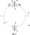
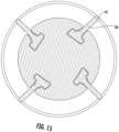
- the brushroll assembly 420 has a plurality of couplers 440a, 440b circumferentially arranged on a circumferential surface of the agitator body 422, extending axially along the agitator body 422.
- a first cleaning vane434 has a longitudinal first edge 434a and a longitudinal second edge 434b. The first edge 434a and the second edge 434b of the cleaning vane 434 slidably connect to a corresponding first coupler 440a and second coupler 440b of the plurality of couplers 440.
- the cleaning vane 434 covers the length of the agitator body 422, however, in other embodiments, the cleaning vane 434 covers only a portion of the length of the agitator body 422.
- the first end 434a and the second end 434b of the cleaning vane 434 are integrally molded with the first coupler 440a and second coupler 440b, respectively.
- the first cleaning vane 434 forms a loop 435 between the longitudinal edges that extends outwardly away from the agitator body 422.
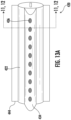
- the cleaning vane 434 includes a plurality of holes 442 extending through the cleaning vane 434 between the first edge 434a and the second edge 434b.
- a row of bristles 436 may be tufted through the plurality of holes 442 in the cleaning vane 434 and attached to a corresponding plurality of bristle holes 437 on the agitator body 422 ( Fig. 11 ).
- a plurality of bristle receptacles 439 are integrally molded with the cleaning vane 434 along the length of the cleaning vane.
- the row of bristles 436 are tufted into the bristle receptacles 439.
- the bristle receptacles 439 secure and retain the bristles 436.
- the bristles 436 and bristle receptacles 439 are separate and apart from the agitator body 422.
- the first cleaning vane 434 may be composed of an elastomeric material, vinyl, woven fiber or a similar material.
- the flexibility of the first cleaning vane 434 material increases durability and longevity of the cleaner. Further, the flexibility of the first cleaning vane 434 allows the cleaner to flex and bend during operation, which reduces debris wrap around the agitator body 422 by not allowing the hair and debris a stationary portion to wrap around.
- the row of bristles 436 provide agitation to the surface 50 to be cleaned to improve cleaning performance and debris pick-up.
- the loop 435 of the first cleaning vane 434 increases the circumference of the agitator body 422.
- the agitator body 422 may include secondary cleaning members 444 configured to further enhance debris pick-up and inhibit debris and hair wrap around the agitator body 422.
- the secondary cleaning members 444 may be composed of the same material as the first cleaning vane 434, or a different material.
- the housing 14 further includes an extending portion or protrusion 56 directed inwardly towards the agitator body 22.
- the extending portion or protrusion 56 may extend from a central location of the housing 14, as shown in Figs. 5 and 6 , however the protrusion may extend anywhere in the housing 14 between the first end 24 and the second end 26.
- the extending portion 56 is configured to contact the surface engaging portion 35 of the agitating members.
- the extending portion 56 provides a flicking-type action to the agitating members 32 to inhibit hair and debris wrap around the agitator body 22.
- the flicking action inhibits hair and debris wrap primarily by creating vibration and movement of the agitating members 32 that then vibrate and move the hair and debris, facilitating removal through a suction opening 58.
- Another beneficial aspect of the flicking action by the extending portion 56 is the direct contact with the hair and debris. This direct contact helps inhibit the hair and debris from becoming tightly wound around the agitator body 22.
- the extending portion 56 is positioned adjacent the suction opening 58 to facilitate the uptake of the dislodged hair and debris into the working air path.
- the extending portion 56 has a length along the brushroll axis in the longitudinal direction between 3 and 25 millimeters contacting the surface engaging portion 35 of the vane as the vane rotates past the extending portion 56 in operation.
- the extending portion 56 has a length in the longitudinal direction of between 25 and 50 millimeters contacting the surface engaging portion 35 of the vane as the vane rotates past the extending portion 56 in operation.
- the extending portion 56 also inhibits hair and debris overcoming the deformable member 38 and entering the bearing 28.
Landscapes
- Engineering & Computer Science (AREA)
- Mechanical Engineering (AREA)
- Nozzles For Electric Vacuum Cleaners (AREA)
- Organic Low-Molecular-Weight Compounds And Preparation Thereof (AREA)
Claims (15)
- Nettoyeur de sol (10) comprenant :une chambre de collecte de saleté (52) ; etune tête de nettoyage (12) en communication fluidique avec la chambre de collecte de saleté (52),la tête de nettoyage (12) comprenantun logement (14) ;une chambre de rouleau brosseur (16) ayant une ouverture (18) dans un côté inférieur du logement (14) ; etun ensemble rouleau brosseur (20) monté en fonctionnement dans la chambre de rouleau brosseur (16) et ayantun corps d'agitateur (22) ayant une première extrémité (24), et une seconde extrémité (26) opposée à la première extrémité (24, 224), et un axe longitudinal (100) qui s'étend à travers la première extrémité (24, 224) et la seconde extrémité (26, 226), le corps d'agitateur (22) pouvant tourner autour de l'axe longitudinal (100), et le corps d'agitateur (22) comprenant en outre une première et une seconde saillie annulaire concentrique (66', 66'') sur la première extrémité (24, 224) s'étendant le long de l'axe longitudinal (100),un palier (28) en communication rotative avec la première extrémité (24, 224) du corps d'agitateur (22),un bouchon d'extrémité (30) retenant le palier (28), le bouchon d'extrémité (30) monté amovible sur le logement (14) positionnant la première extrémité (24, 224) du rouleau brosseur (20) dans la chambre de rouleau brosseur (16), le bouchon d'extrémité (30) comprenant un côté externe (53) orienté à l'opposé du corps d'agitateur (22) et un côté interne (51) faisant face à la première extrémité (24, 224) du corps d'agitateur (22), le côté interne (51) comprenant une première et une seconde nervure annulaire concentrique (64', 64"),dans lequel les première et seconde nervures annulaires (64', 64'') et les première et seconde saillies annulaires (66', 66") se chevauchent, de façon à former une pluralité d'évidements annulaires (67) entre les nervures annulaires (64', 64") et les saillies annulaires (66', 66'') adjacentes, un évidement annulaire le plus extérieur (67') étant formé entre la première nervure annulaire (64') et la première saillie annulaire (66'),une pluralité d'organes d'agitation (32) s'étendant le long du corps d'agitateur (22) entre la première extrémité (24) et la seconde extrémité (26) qui s'étendent à travers l'ouverture (18), etun organe déformable (38) s'étendant depuis le corps d'agitateur (22) transversalement à l'axe longitudinal (100) et positionné le long d'une surface circonférentielle (47) du corps d'agitateur (22) entre la pluralité d'organes d'agitation (32) et le bouchon d'extrémité (30), l'organe déformable (38) étant positionné adjacent à l'évidement annulaire le plus extérieur (67') et conçu pour empêcher des débris de rencontrer l'évidement annulaire le plus extérieur (67').
- Tête de nettoyage (12) selon la revendication 1, dans laquelle l'organe déformable (38) comprend un joint annulaire adjacent à la première extrémité (24, 224) du corps d'agitateur (22) et adjacent au bouchon d'extrémité (30), l'organe déformable (38) étant conçu pour empêcher des débris de rencontrer l'évidement annulaire le plus extérieur (67').
- Tête de nettoyage (12) selon la revendication 1, dans laquelle le bouchon d'extrémité (30) comprend un joint à labyrinthe (52) autour du palier (28), ou facultativement dans laquelle l'organe déformable (38) comprend un matériau feutré.
- Tête de nettoyage (12) selon la revendication 1, dans laquelle le corps d'agitateur (22) comprend une rainure le long de la surface circonférentielle (47) à la première extrémité (24, 224) entre la pluralité d'organes d'agitation (32) et le bouchon d'extrémité (30), la rainure (37) étant conçue pour recevoir et retenir l'organe déformable (38) pendant le fonctionnement.
- Tête de nettoyage (12) selon la revendication 1, dans laquelle :l'organe déformable (38) est fixé au corps d'agitateur (22) et peut tourner avec celui-ci ; ou facultativement dans laquelle l'organe déformable (38) est positionné entre le bouchon d'extrémité (30) et le corps d'agitateur (22) et est en prise de contact avec au moins l'un du bouchon d'extrémité (30) et du corps d'agitateur (22) ; ou facultativementdans laquelle l'organe déformable (38) s'étend dans un plan perpendiculaire à l'étendue longitudinale du corps d'agitateur (22).
- Tête de nettoyage (12) selon la revendication 1, comprenant en outre un mécanisme d'entraînement d'agitateur dans le logement (14), le mécanisme d'entraînement ayant un organe d'entraînement (54) en prise fonctionnelle avec la seconde extrémité (26, 226) du corps d'agitateur (22) ; l'ensemble rouleau brosseur (20) comprenant en outre
un second organe déformable (38') s'étendant radialement depuis le corps d'agitateur (22) positionné le long d'une surface circonférentielle (47) du corps d'agitateur (22) entre la pluralité d'organes d'agitation (32) et l'organe d'entraînement (54). - Tête de nettoyage (12) selon la revendication 6, dans laquelle au moins l'un du premier et du second organe déformable (38, 38') s'étend à travers l'ouverture (18) pendant le fonctionnement pour entrer en contact avec la surface à nettoyer.
- Tête de nettoyage (12) selon la revendication 7, dans laquelle la pluralité d'organes d'agitation (32) comprend une ou plusieurs ailettes (34, 234) et le second organe déformable (38') est positionné à une extrémité de la ou des ailettes (34, 234), et facultativement
dans laquelle chaque ailette (34, 234) a une partie de prise de surface (35) s'étendant longitudinalement le long du corps d'agitateur (22) entre une première extrémité d'ailette (31) adjacente à la première extrémité (24, 224) et une seconde extrémité d'ailette (33) adjacente à la seconde extrémité (26, 226), et dans laquelle le second organe déformable (38') est positionné entre la seconde extrémité d'ailette (33) et l'organe d'entraînement (54). - Tête de nettoyage (12) selon la revendication 1, dans laquelle l'organe déformable (38) a une région intérieure dotée d'un premier organe de liaison (43) qui est couplé à un second organe de liaison (45) sur la surface circonférentielle (47) du corps d'agitateur (22).
- Tête de nettoyage (12) selon la revendication 1, dans laquelle la pluralité d'organes d'agitation (32) comprend un motif de crins (36, 236), et facultativement
dans laquelle le motif de crins (36, 236) s'étend entre la première extrémité (24, 224) et la seconde extrémité (26, 226) en une rangée hélicoïdale. - Tête de nettoyage (12) selon la revendication 1, dans laquelle la pluralité d'organes d'agitation (32) comprend une pluralité d'ailettes (34, 234) espacées autour de la circonférence du corps d'agitateur (22) et s'étendant vers l'extérieur depuis le corps d'agitateur (22) ; et facultativement
dans laquelle la pluralité d'organes d'agitation (32) comprend en outre au moins un motif de crins (36, 236) s'étendant entre la première extrémité (24, 224) et la seconde extrémité (26, 226), dans laquelle les crins de l'au moins un motif de crins (36, 236) sont espacés d'ailettes adjacentes (34, 234) d'au moins 5 millimètres dans la direction circonférentielle le long du corps d'agitateur (22). - Tête de nettoyage (12) selon la revendication 11, dans laquelle chaque ailette (34, 234) a une partie de prise de surface (35) s'étendant longitudinalement le long du corps d'agitateur (22) entre une première extrémité d'ailette (33) adjacente à la première extrémité (24, 224) et une seconde extrémité d'ailette (35) adjacente à la seconde extrémité (26, 226), dans laquelle le logement (14) comprend une partie d'extension dirigée vers l'intérieur en direction du corps d'agitateur, la partie d'extension (56) étant positionnée à l'intérieur de la chambre de rouleau brosseur (16) entre les première et seconde extrémités (24, 224, 26, 226) et conçue pour entrer en contact avec la partie de prise de surface (35) de l'ailette lorsque l'ailette (34, 234) tourne au-delà de la partie d'extension (56) dans la chambre de rouleau brosseur (16) pendant le fonctionnement, et facultativement dans laquelle :la partie d'extension (56) a une longueur dans l'axe du rouleau brosseur comprise entre 3 et 25 millimètres en contact avec la partie de prise de surface (35) lorsque l'ailette (34, 234) tourne au-delà de la partie d'extension en fonctionnement ; oula partie d'extension (56) a une longueur dans l'axe du rouleau brosseur supérieure à 25 millimètres en contact avec la partie de prise de surface (35) lorsque l'ailette (34, 234) tourne au-delà de la partie d'extension (56) en fonctionnement.
- Tête de nettoyage (12) selon la revendication 1, dans laquelle chacune des au moins trois ailettes (34) s'étend le long d'un pas hélicoïdal constant autour du corps d'agitateur (22) entre la première extrémité (24) et la seconde extrémité (26) et la ou les rangées de crins (36) définissent un motif variable ou oscillant autour du corps d'agitateur (22) entre la première extrémité (24) et la seconde extrémité (26), dans laquelle chacune de la ou des rangées de crins (36) s'étend entre deux ailettes adjacentes (34).
- Tête de nettoyage (12) selon la revendication 1, dans laquelle les organes de la pluralité d'organes d'agitation (32) comprennent au moins trois ailettes (234) et une ou plusieurs rangées de crins (236) s'étendant entre la première extrémité (224) et la seconde extrémité (226), dans laquelle les organes de la pluralité d'organes d'agitation (32) s'étendent de façon hélicoïdale autour du corps d'agitateur (22) entre la première extrémité (224) et la seconde extrémité (226), et facultativementdans laquelle l'hélice des au moins trois ailettes (234) s'étend dans une première direction, et l'hélice de la ou des rangées de crins (236) s'étend dans une seconde direction, opposée à la première direction, et facultativementdans laquelle les au moins trois ailettes (234) s'enroulent de façon hélicoïdale sur environ 180 degrés autour du corps d'agitateur (22) entre la première extrémité (224) et la seconde extrémité (226) dans la première direction, et la ou les rangées de crins (236) s'enroulent de façon hélicoïdale sur environ 360 degrés autour du corps d'agitateur (22) dans la seconde direction.
- Tête de nettoyage (12) selon la revendication 1, dans laquelle le logement (14) comprend une surface extérieure (57) de la tête de nettoyage (12), et dans laquelle le bouchon d'extrémité (30) comprend un côté externe (53) orienté à l'opposé du corps (22) de rouleau brosseur et un côté intérieur (51) faisant face à la première extrémité (24, 224), dans laquelle le bouchon d'extrémité (30) est monté dans le logement (14) de sorte que le côté externe (53) du bouchon d'extrémité forme une partie de la surface extérieure (57).
Applications Claiming Priority (2)
| Application Number | Priority Date | Filing Date | Title |
|---|---|---|---|
| US202062960826P | 2020-01-14 | 2020-01-14 | |
| PCT/US2020/067288 WO2021146050A1 (fr) | 2020-01-14 | 2020-12-29 | Dispositif de nettoyage de sol |
Publications (2)
| Publication Number | Publication Date |
|---|---|
| EP4090209A1 EP4090209A1 (fr) | 2022-11-23 |
| EP4090209B1 true EP4090209B1 (fr) | 2024-11-27 |
Family
ID=74206218
Family Applications (1)
| Application Number | Title | Priority Date | Filing Date |
|---|---|---|---|
| EP20845526.1A Active EP4090209B1 (fr) | 2020-01-14 | 2020-12-29 | Nettoyeur de sol |
Country Status (5)
| Country | Link |
|---|---|
| US (1) | US20210212535A1 (fr) |
| EP (1) | EP4090209B1 (fr) |
| CN (1) | CN115243591B (fr) |
| AU (1) | AU2020423700A1 (fr) |
| WO (1) | WO2021146050A1 (fr) |
Families Citing this family (11)
| Publication number | Priority date | Publication date | Assignee | Title |
|---|---|---|---|---|
| USD987926S1 (en) * | 2021-04-26 | 2023-05-30 | Bissell Inc. | Brushroll for a floor cleaner |
| GB2606154B (en) * | 2021-04-26 | 2023-12-27 | Dyson Technology Ltd | Brushbar for a vacuum cleaner |
| KR102717319B1 (ko) * | 2022-03-11 | 2024-10-16 | 엘지전자 주식회사 | 청소기 |
| CN116921290A (zh) * | 2022-07-04 | 2023-10-24 | 北京顺造科技有限公司 | 搅拌器、表面清洁设备及搅拌器用环形带制造方法 |
| US20240156221A1 (en) * | 2022-11-11 | 2024-05-16 | Sean David Tilley | Cleaning Device for Contacting Surfaces of Sports Equipment |
| WO2025060789A1 (fr) * | 2023-09-22 | 2025-03-27 | 深圳市晨北科技有限公司 | Brosse roulante et dispositif de nettoyage |
| USD1114445S1 (en) * | 2023-12-05 | 2026-02-17 | Suzhou Rongxuan Electric Co., Ltd | Floor brush |
| USD1094935S1 (en) * | 2024-01-02 | 2025-09-23 | Calor | Vacuum cleaner suction head |
| CN118000609B (zh) * | 2024-04-08 | 2024-06-04 | 苏州荣炫电器有限公司 | 滚刷体、地刷头、刷毛结构和吸尘器 |
| CN118417208B (zh) * | 2024-07-04 | 2024-08-30 | 中铁电气化局集团有限公司 | 一种用于绝缘子的智能清洁装置 |
| USD1084574S1 (en) * | 2024-12-20 | 2025-07-15 | Suzhou Rongxuan Electric Co., Ltd | Floor brush |
Family Cites Families (18)
| Publication number | Priority date | Publication date | Assignee | Title |
|---|---|---|---|---|
| US1999696A (en) * | 1933-05-05 | 1935-04-30 | Hoover Co | Suction cleaner |
| US2734211A (en) * | 1950-04-07 | 1956-02-14 | vance | |
| US2707792A (en) * | 1950-11-24 | 1955-05-10 | Henney Motor Company Inc | Rotary brush for suction cleaners |
| FR1077106A (fr) * | 1953-03-21 | 1954-11-04 | Boyer Metallurg | Perfectionnements apportés aux dispositifs du genre des roulements, notamment pour rouleaux de transporteurs |
| EP0015738B1 (fr) * | 1979-03-09 | 1984-03-07 | Skf (U.K.) Limited | Aménagements de paliers pour rouleaux transporteurs munis de capuchons d'extrémité |
| US5272785A (en) * | 1989-12-26 | 1993-12-28 | The Scott Fetzer Company | Brushroll |
| US5465451A (en) * | 1989-12-26 | 1995-11-14 | The Scott Fetzer Company | Brushroll |
| US5435038A (en) * | 1994-03-10 | 1995-07-25 | Sauers; Carl B. | Brush roller assembly for vacuum cleaner sweeper |
| US6591441B2 (en) * | 2001-10-10 | 2003-07-15 | The Scott Fetzer Company | Brushroll having improved cleaning capability |
| US6810559B2 (en) * | 2002-02-27 | 2004-11-02 | Superior Brush Company | Agitator assembly for vacuum cleaner |
| DE102004046383B4 (de) * | 2004-09-24 | 2009-06-18 | Stein & Co Gmbh | Vorrichtung für Bürstwalze von Bodenpflegegeräten |
| US20060272122A1 (en) * | 2005-06-07 | 2006-12-07 | Dennis Butler | Vacuum brushroll edge cleaner |
| GB2440282B (en) * | 2005-06-07 | 2008-05-14 | Electrolux Home Care Prod Na | Vacuum brushroll edge cleaner |
| CN103637747B (zh) * | 2008-03-17 | 2017-04-12 | 伊莱克斯家用产品有限公司 | 具有清洁部件的搅拌器 |
| JP5505158B2 (ja) * | 2010-07-20 | 2014-05-28 | 三菱電機株式会社 | 床面吸込具、及び、この床面吸込具を用いた電気掃除機 |
| US9693663B2 (en) * | 2013-03-15 | 2017-07-04 | Bissell Homecare, Inc. | Tufting method and brushroll for vacuum cleaner |
| CN114403741B (zh) * | 2017-03-10 | 2024-02-27 | 尚科宁家运营有限公司 | 具有清除器和去除毛发的搅拌器 |
| US11247245B2 (en) * | 2017-12-27 | 2022-02-15 | Sharkninja Operating Llc | Cleaning apparatus with anti-hair wrap management systems |
-
2020
- 2020-12-29 WO PCT/US2020/067288 patent/WO2021146050A1/fr not_active Ceased
- 2020-12-29 AU AU2020423700A patent/AU2020423700A1/en not_active Abandoned
- 2020-12-29 CN CN202080096061.6A patent/CN115243591B/zh active Active
- 2020-12-29 EP EP20845526.1A patent/EP4090209B1/fr active Active
- 2020-12-29 US US17/136,450 patent/US20210212535A1/en not_active Abandoned
Also Published As
| Publication number | Publication date |
|---|---|
| CN115243591A (zh) | 2022-10-25 |
| CN115243591B (zh) | 2024-10-25 |
| AU2020423700A1 (en) | 2022-07-28 |
| US20210212535A1 (en) | 2021-07-15 |
| EP4090209A1 (fr) | 2022-11-23 |
| WO2021146050A1 (fr) | 2021-07-22 |
Similar Documents
| Publication | Publication Date | Title |
|---|---|---|
| US20210212535A1 (en) | Floor cleaner | |
| US20240172907A1 (en) | Floor cleaner | |
| JP7152837B2 (ja) | 表面処理装置ための攪拌器及びそれを有する表面処理装置 | |
| US11672393B2 (en) | Cleaning apparatus with selectable combing unit for removing debris from cleaning roller | |
| US4912805A (en) | Dual-purpose rotating brush for vacuum cleaner | |
| KR102546702B1 (ko) | 진공청소기 | |
| KR100470557B1 (ko) | 먼지 털이용 회전롤러를 구비한 진공청소기용 흡입브러시조립체 | |
| US12207781B2 (en) | Cleaner | |
| KR102807469B1 (ko) | 진공청소기 | |
| EP3709852B1 (fr) | Appareil de nettoyage de surface | |
| EP4041040B1 (fr) | Tête de nettoyage pour un appareil aspirateur | |
| EP3731714B1 (fr) | Appareil de nettoyage avec unité de peignage sélectionnable permettant de retirer des débris d'un rouleau de nettoyage | |
| EP1827193B1 (fr) | Agitateur pour buse d'aspiration dans un aspirateur | |
| JP2024517304A (ja) | 掃除機用床ブラシアッセンブリ及び掃除機 | |
| CN111655106A (zh) | 可旋转的清洁辊和具有这种清洁辊的清扫装置 | |
| CN213757078U (zh) | 滚刷及具有其的清洁装置 | |
| JP2023545771A (ja) | 表面処理装置ための撹拌器およびそれを有する表面処理装置 | |
| KR100480142B1 (ko) | 진공청소기의 흡입헤드 | |
| CN220512776U (zh) | 滚刷组件和清洁设备 | |
| CN223169682U (zh) | 清洁设备 | |
| JP2022111676A (ja) | ブラシ及び回転ブラシ | |
| WO2026077342A1 (fr) | Brosse à rouleau, dispositif de nettoyage et système de nettoyage | |
| JPH04314411A (ja) | 電気掃除機の吸込口体 | |
| JPH0588467U (ja) | 掃除機用吸入ノズルの回転ロータ | |
| KR20230133653A (ko) | 청소기 |
Legal Events
| Date | Code | Title | Description |
|---|---|---|---|
| STAA | Information on the status of an ep patent application or granted ep patent |
Free format text: STATUS: UNKNOWN |
|
| STAA | Information on the status of an ep patent application or granted ep patent |
Free format text: STATUS: THE INTERNATIONAL PUBLICATION HAS BEEN MADE |
|
| PUAI | Public reference made under article 153(3) epc to a published international application that has entered the european phase |
Free format text: ORIGINAL CODE: 0009012 |
|
| STAA | Information on the status of an ep patent application or granted ep patent |
Free format text: STATUS: REQUEST FOR EXAMINATION WAS MADE |
|
| 17P | Request for examination filed |
Effective date: 20220711 |
|
| AK | Designated contracting states |
Kind code of ref document: A1 Designated state(s): AL AT BE BG CH CY CZ DE DK EE ES FI FR GB GR HR HU IE IS IT LI LT LU LV MC MK MT NL NO PL PT RO RS SE SI SK SM TR |
|
| DAV | Request for validation of the european patent (deleted) | ||
| DAX | Request for extension of the european patent (deleted) | ||
| GRAP | Despatch of communication of intention to grant a patent |
Free format text: ORIGINAL CODE: EPIDOSNIGR1 |
|
| STAA | Information on the status of an ep patent application or granted ep patent |
Free format text: STATUS: GRANT OF PATENT IS INTENDED |
|
| INTG | Intention to grant announced |
Effective date: 20240215 |
|
| GRAJ | Information related to disapproval of communication of intention to grant by the applicant or resumption of examination proceedings by the epo deleted |
Free format text: ORIGINAL CODE: EPIDOSDIGR1 |
|
| STAA | Information on the status of an ep patent application or granted ep patent |
Free format text: STATUS: REQUEST FOR EXAMINATION WAS MADE |
|
| GRAP | Despatch of communication of intention to grant a patent |
Free format text: ORIGINAL CODE: EPIDOSNIGR1 |
|
| STAA | Information on the status of an ep patent application or granted ep patent |
Free format text: STATUS: GRANT OF PATENT IS INTENDED |
|
| INTC | Intention to grant announced (deleted) | ||
| INTG | Intention to grant announced |
Effective date: 20240618 |
|
| P01 | Opt-out of the competence of the unified patent court (upc) registered |
Free format text: CASE NUMBER: APP_39852/2024 Effective date: 20240704 |
|
| GRAJ | Information related to disapproval of communication of intention to grant by the applicant or resumption of examination proceedings by the epo deleted |
Free format text: ORIGINAL CODE: EPIDOSDIGR1 |
|
| STAA | Information on the status of an ep patent application or granted ep patent |
Free format text: STATUS: REQUEST FOR EXAMINATION WAS MADE |
|
| GRAP | Despatch of communication of intention to grant a patent |
Free format text: ORIGINAL CODE: EPIDOSNIGR1 |
|
| STAA | Information on the status of an ep patent application or granted ep patent |
Free format text: STATUS: GRANT OF PATENT IS INTENDED |
|
| INTC | Intention to grant announced (deleted) | ||
| INTG | Intention to grant announced |
Effective date: 20240902 |
|
| GRAS | Grant fee paid |
Free format text: ORIGINAL CODE: EPIDOSNIGR3 |
|
| GRAA | (expected) grant |
Free format text: ORIGINAL CODE: 0009210 |
|
| STAA | Information on the status of an ep patent application or granted ep patent |
Free format text: STATUS: THE PATENT HAS BEEN GRANTED |
|
| AK | Designated contracting states |
Kind code of ref document: B1 Designated state(s): AL AT BE BG CH CY CZ DE DK EE ES FI FR GB GR HR HU IE IS IT LI LT LU LV MC MK MT NL NO PL PT RO RS SE SI SK SM TR |
|
| REG | Reference to a national code |
Ref country code: GB Ref legal event code: FG4D |
|
| REG | Reference to a national code |
Ref country code: CH Ref legal event code: EP |
|
| REG | Reference to a national code |
Ref country code: DE Ref legal event code: R096 Ref document number: 602020042212 Country of ref document: DE |
|
| REG | Reference to a national code |
Ref country code: IE Ref legal event code: FG4D |
|
| REG | Reference to a national code |
Ref country code: LT Ref legal event code: MG9D |
|
| REG | Reference to a national code |
Ref country code: NL Ref legal event code: MP Effective date: 20241127 |
|
| PG25 | Lapsed in a contracting state [announced via postgrant information from national office to epo] |
Ref country code: HR Free format text: LAPSE BECAUSE OF FAILURE TO SUBMIT A TRANSLATION OF THE DESCRIPTION OR TO PAY THE FEE WITHIN THE PRESCRIBED TIME-LIMIT Effective date: 20241127 Ref country code: IS Free format text: LAPSE BECAUSE OF FAILURE TO SUBMIT A TRANSLATION OF THE DESCRIPTION OR TO PAY THE FEE WITHIN THE PRESCRIBED TIME-LIMIT Effective date: 20250327 Ref country code: PT Free format text: LAPSE BECAUSE OF FAILURE TO SUBMIT A TRANSLATION OF THE DESCRIPTION OR TO PAY THE FEE WITHIN THE PRESCRIBED TIME-LIMIT Effective date: 20250327 |
|
| PG25 | Lapsed in a contracting state [announced via postgrant information from national office to epo] |
Ref country code: FI Free format text: LAPSE BECAUSE OF FAILURE TO SUBMIT A TRANSLATION OF THE DESCRIPTION OR TO PAY THE FEE WITHIN THE PRESCRIBED TIME-LIMIT Effective date: 20241127 Ref country code: NL Free format text: LAPSE BECAUSE OF FAILURE TO SUBMIT A TRANSLATION OF THE DESCRIPTION OR TO PAY THE FEE WITHIN THE PRESCRIBED TIME-LIMIT Effective date: 20241127 |
|
| REG | Reference to a national code |
Ref country code: AT Ref legal event code: MK05 Ref document number: 1744853 Country of ref document: AT Kind code of ref document: T Effective date: 20241127 |
|
| PG25 | Lapsed in a contracting state [announced via postgrant information from national office to epo] |
Ref country code: BG Free format text: LAPSE BECAUSE OF FAILURE TO SUBMIT A TRANSLATION OF THE DESCRIPTION OR TO PAY THE FEE WITHIN THE PRESCRIBED TIME-LIMIT Effective date: 20241127 |
|
| PG25 | Lapsed in a contracting state [announced via postgrant information from national office to epo] |
Ref country code: ES Free format text: LAPSE BECAUSE OF FAILURE TO SUBMIT A TRANSLATION OF THE DESCRIPTION OR TO PAY THE FEE WITHIN THE PRESCRIBED TIME-LIMIT Effective date: 20241127 |
|
| PG25 | Lapsed in a contracting state [announced via postgrant information from national office to epo] |
Ref country code: NO Free format text: LAPSE BECAUSE OF FAILURE TO SUBMIT A TRANSLATION OF THE DESCRIPTION OR TO PAY THE FEE WITHIN THE PRESCRIBED TIME-LIMIT Effective date: 20250227 |
|
| PG25 | Lapsed in a contracting state [announced via postgrant information from national office to epo] |
Ref country code: LV Free format text: LAPSE BECAUSE OF FAILURE TO SUBMIT A TRANSLATION OF THE DESCRIPTION OR TO PAY THE FEE WITHIN THE PRESCRIBED TIME-LIMIT Effective date: 20241127 Ref country code: AT Free format text: LAPSE BECAUSE OF FAILURE TO SUBMIT A TRANSLATION OF THE DESCRIPTION OR TO PAY THE FEE WITHIN THE PRESCRIBED TIME-LIMIT Effective date: 20241127 Ref country code: GR Free format text: LAPSE BECAUSE OF FAILURE TO SUBMIT A TRANSLATION OF THE DESCRIPTION OR TO PAY THE FEE WITHIN THE PRESCRIBED TIME-LIMIT Effective date: 20250228 |
|
| PG25 | Lapsed in a contracting state [announced via postgrant information from national office to epo] |
Ref country code: PL Free format text: LAPSE BECAUSE OF FAILURE TO SUBMIT A TRANSLATION OF THE DESCRIPTION OR TO PAY THE FEE WITHIN THE PRESCRIBED TIME-LIMIT Effective date: 20241127 |
|
| PGFP | Annual fee paid to national office [announced via postgrant information from national office to epo] |
Ref country code: FR Payment date: 20250128 Year of fee payment: 6 |
|
| PG25 | Lapsed in a contracting state [announced via postgrant information from national office to epo] |
Ref country code: RS Free format text: LAPSE BECAUSE OF FAILURE TO SUBMIT A TRANSLATION OF THE DESCRIPTION OR TO PAY THE FEE WITHIN THE PRESCRIBED TIME-LIMIT Effective date: 20250227 |
|
| PG25 | Lapsed in a contracting state [announced via postgrant information from national office to epo] |
Ref country code: SM Free format text: LAPSE BECAUSE OF FAILURE TO SUBMIT A TRANSLATION OF THE DESCRIPTION OR TO PAY THE FEE WITHIN THE PRESCRIBED TIME-LIMIT Effective date: 20241127 |
|
| PG25 | Lapsed in a contracting state [announced via postgrant information from national office to epo] |
Ref country code: DK Free format text: LAPSE BECAUSE OF FAILURE TO SUBMIT A TRANSLATION OF THE DESCRIPTION OR TO PAY THE FEE WITHIN THE PRESCRIBED TIME-LIMIT Effective date: 20241127 |
|
| PG25 | Lapsed in a contracting state [announced via postgrant information from national office to epo] |
Ref country code: EE Free format text: LAPSE BECAUSE OF FAILURE TO SUBMIT A TRANSLATION OF THE DESCRIPTION OR TO PAY THE FEE WITHIN THE PRESCRIBED TIME-LIMIT Effective date: 20241127 |
|
| PG25 | Lapsed in a contracting state [announced via postgrant information from national office to epo] |
Ref country code: RO Free format text: LAPSE BECAUSE OF FAILURE TO SUBMIT A TRANSLATION OF THE DESCRIPTION OR TO PAY THE FEE WITHIN THE PRESCRIBED TIME-LIMIT Effective date: 20241127 |
|
| PG25 | Lapsed in a contracting state [announced via postgrant information from national office to epo] |
Ref country code: SK Free format text: LAPSE BECAUSE OF FAILURE TO SUBMIT A TRANSLATION OF THE DESCRIPTION OR TO PAY THE FEE WITHIN THE PRESCRIBED TIME-LIMIT Effective date: 20241127 |
|
| PG25 | Lapsed in a contracting state [announced via postgrant information from national office to epo] |
Ref country code: CZ Free format text: LAPSE BECAUSE OF FAILURE TO SUBMIT A TRANSLATION OF THE DESCRIPTION OR TO PAY THE FEE WITHIN THE PRESCRIBED TIME-LIMIT Effective date: 20241127 |
|
| PG25 | Lapsed in a contracting state [announced via postgrant information from national office to epo] |
Ref country code: IT Free format text: LAPSE BECAUSE OF FAILURE TO SUBMIT A TRANSLATION OF THE DESCRIPTION OR TO PAY THE FEE WITHIN THE PRESCRIBED TIME-LIMIT Effective date: 20241127 |
|
| REG | Reference to a national code |
Ref country code: CH Ref legal event code: PL |
|
| PG25 | Lapsed in a contracting state [announced via postgrant information from national office to epo] |
Ref country code: LU Free format text: LAPSE BECAUSE OF NON-PAYMENT OF DUE FEES Effective date: 20241229 |
|
| REG | Reference to a national code |
Ref country code: DE Ref legal event code: R097 Ref document number: 602020042212 Country of ref document: DE |
|
| PG25 | Lapsed in a contracting state [announced via postgrant information from national office to epo] |
Ref country code: SE Free format text: LAPSE BECAUSE OF FAILURE TO SUBMIT A TRANSLATION OF THE DESCRIPTION OR TO PAY THE FEE WITHIN THE PRESCRIBED TIME-LIMIT Effective date: 20241127 |
|
| PG25 | Lapsed in a contracting state [announced via postgrant information from national office to epo] |
Ref country code: MC Free format text: LAPSE BECAUSE OF FAILURE TO SUBMIT A TRANSLATION OF THE DESCRIPTION OR TO PAY THE FEE WITHIN THE PRESCRIBED TIME-LIMIT Effective date: 20241127 |
|
| PLBE | No opposition filed within time limit |
Free format text: ORIGINAL CODE: 0009261 |
|
| STAA | Information on the status of an ep patent application or granted ep patent |
Free format text: STATUS: NO OPPOSITION FILED WITHIN TIME LIMIT |
|
| REG | Reference to a national code |
Ref country code: BE Ref legal event code: MM Effective date: 20241231 |
|
| PG25 | Lapsed in a contracting state [announced via postgrant information from national office to epo] |
Ref country code: BE Free format text: LAPSE BECAUSE OF NON-PAYMENT OF DUE FEES Effective date: 20241231 |
|
| PG25 | Lapsed in a contracting state [announced via postgrant information from national office to epo] |
Ref country code: CH Free format text: LAPSE BECAUSE OF NON-PAYMENT OF DUE FEES Effective date: 20241231 |
|
| PG25 | Lapsed in a contracting state [announced via postgrant information from national office to epo] |
Ref country code: IE Free format text: LAPSE BECAUSE OF NON-PAYMENT OF DUE FEES Effective date: 20241229 |
|
| 26N | No opposition filed |
Effective date: 20250828 |
|
| PGFP | Annual fee paid to national office [announced via postgrant information from national office to epo] |
Ref country code: GB Payment date: 20251229 Year of fee payment: 6 |
|
| PGFP | Annual fee paid to national office [announced via postgrant information from national office to epo] |
Ref country code: DE Payment date: 20251229 Year of fee payment: 6 |
|
| PG25 | Lapsed in a contracting state [announced via postgrant information from national office to epo] |
Ref country code: CY Free format text: LAPSE BECAUSE OF FAILURE TO SUBMIT A TRANSLATION OF THE DESCRIPTION OR TO PAY THE FEE WITHIN THE PRESCRIBED TIME-LIMIT Effective date: 20241127 |