EP4090396B1 - Dispositif d'extrémité externe et méthode pour sa connexion à des conduites d'écoulement - Google Patents
Dispositif d'extrémité externe et méthode pour sa connexion à des conduites d'écoulement Download PDFInfo
- Publication number
- EP4090396B1 EP4090396B1 EP21701595.7A EP21701595A EP4090396B1 EP 4090396 B1 EP4090396 B1 EP 4090396B1 EP 21701595 A EP21701595 A EP 21701595A EP 4090396 B1 EP4090396 B1 EP 4090396B1
- Authority
- EP
- European Patent Office
- Prior art keywords
- pair
- piercing
- connecting conduit
- casing
- catheter
- Prior art date
- Legal status (The legal status is an assumption and is not a legal conclusion. Google has not performed a legal analysis and makes no representation as to the accuracy of the status listed.)
- Active
Links
Images




Classifications
-
- A—HUMAN NECESSITIES
- A61—MEDICAL OR VETERINARY SCIENCE; HYGIENE
- A61M—DEVICES FOR INTRODUCING MEDIA INTO, OR ONTO, THE BODY; DEVICES FOR TRANSDUCING BODY MEDIA OR FOR TAKING MEDIA FROM THE BODY; DEVICES FOR PRODUCING OR ENDING SLEEP OR STUPOR
- A61M1/00—Suction or pumping devices for medical purposes; Devices for carrying-off, for treatment of, or for carrying-over, body-liquids; Drainage systems
- A61M1/36—Other treatment of blood in a by-pass of the natural circulatory system, e.g. temperature adaptation, irradiation ; Extra-corporeal blood circuits
- A61M1/3621—Extra-corporeal blood circuits
- A61M1/3653—Interfaces between patient blood circulation and extra-corporal blood circuit
-
- A—HUMAN NECESSITIES
- A61—MEDICAL OR VETERINARY SCIENCE; HYGIENE
- A61M—DEVICES FOR INTRODUCING MEDIA INTO, OR ONTO, THE BODY; DEVICES FOR TRANSDUCING BODY MEDIA OR FOR TAKING MEDIA FROM THE BODY; DEVICES FOR PRODUCING OR ENDING SLEEP OR STUPOR
- A61M39/00—Tubes, tube connectors, tube couplings, valves, access sites or the like, specially adapted for medical use
- A61M39/10—Tube connectors; Tube couplings
-
- A—HUMAN NECESSITIES
- A61—MEDICAL OR VETERINARY SCIENCE; HYGIENE
- A61B—DIAGNOSIS; SURGERY; IDENTIFICATION
- A61B2562/00—Details of sensors; Constructional details of sensor housings or probes; Accessories for sensors
- A61B2562/22—Arrangements of medical sensors with cables or leads; Connectors or couplings specifically adapted for medical sensors
- A61B2562/225—Connectors or couplings
-
- A—HUMAN NECESSITIES
- A61—MEDICAL OR VETERINARY SCIENCE; HYGIENE
- A61B—DIAGNOSIS; SURGERY; IDENTIFICATION
- A61B5/00—Measuring for diagnostic purposes; Identification of persons
- A61B5/145—Measuring characteristics of blood in vivo, e.g. gas concentration or pH-value ; Measuring characteristics of body fluids or tissues, e.g. interstitial fluid or cerebral tissue
- A61B5/14532—Measuring characteristics of blood in vivo, e.g. gas concentration or pH-value ; Measuring characteristics of body fluids or tissues, e.g. interstitial fluid or cerebral tissue for measuring glucose, e.g. by tissue impedance measurement
-
- A—HUMAN NECESSITIES
- A61—MEDICAL OR VETERINARY SCIENCE; HYGIENE
- A61B—DIAGNOSIS; SURGERY; IDENTIFICATION
- A61B5/00—Measuring for diagnostic purposes; Identification of persons
- A61B5/145—Measuring characteristics of blood in vivo, e.g. gas concentration or pH-value ; Measuring characteristics of body fluids or tissues, e.g. interstitial fluid or cerebral tissue
- A61B5/1455—Measuring characteristics of blood in vivo, e.g. gas concentration or pH-value ; Measuring characteristics of body fluids or tissues, e.g. interstitial fluid or cerebral tissue using optical sensors, e.g. spectral photometrical oximeters
- A61B5/14551—Measuring characteristics of blood in vivo, e.g. gas concentration or pH-value ; Measuring characteristics of body fluids or tissues, e.g. interstitial fluid or cerebral tissue using optical sensors, e.g. spectral photometrical oximeters for measuring blood gases
- A61B5/14557—Measuring characteristics of blood in vivo, e.g. gas concentration or pH-value ; Measuring characteristics of body fluids or tissues, e.g. interstitial fluid or cerebral tissue using optical sensors, e.g. spectral photometrical oximeters for measuring blood gases specially adapted to extracorporeal circuits
-
- A—HUMAN NECESSITIES
- A61—MEDICAL OR VETERINARY SCIENCE; HYGIENE
- A61B—DIAGNOSIS; SURGERY; IDENTIFICATION
- A61B5/00—Measuring for diagnostic purposes; Identification of persons
- A61B5/68—Arrangements of detecting, measuring or recording means, e.g. sensors, in relation to patient
- A61B5/6846—Arrangements of detecting, measuring or recording means, e.g. sensors, in relation to patient specially adapted to be brought in contact with an internal body part, i.e. invasive
- A61B5/6847—Arrangements of detecting, measuring or recording means, e.g. sensors, in relation to patient specially adapted to be brought in contact with an internal body part, i.e. invasive mounted on an invasive device
- A61B5/6866—Extracorporeal blood circuits, e.g. dialysis circuits
-
- A—HUMAN NECESSITIES
- A61—MEDICAL OR VETERINARY SCIENCE; HYGIENE
- A61M—DEVICES FOR INTRODUCING MEDIA INTO, OR ONTO, THE BODY; DEVICES FOR TRANSDUCING BODY MEDIA OR FOR TAKING MEDIA FROM THE BODY; DEVICES FOR PRODUCING OR ENDING SLEEP OR STUPOR
- A61M1/00—Suction or pumping devices for medical purposes; Devices for carrying-off, for treatment of, or for carrying-over, body-liquids; Drainage systems
- A61M1/14—Dialysis systems; Artificial kidneys; Blood oxygenators ; Reciprocating systems for treatment of body fluids, e.g. single needle systems for hemofiltration or pheresis
-
- A—HUMAN NECESSITIES
- A61—MEDICAL OR VETERINARY SCIENCE; HYGIENE
- A61M—DEVICES FOR INTRODUCING MEDIA INTO, OR ONTO, THE BODY; DEVICES FOR TRANSDUCING BODY MEDIA OR FOR TAKING MEDIA FROM THE BODY; DEVICES FOR PRODUCING OR ENDING SLEEP OR STUPOR
- A61M1/00—Suction or pumping devices for medical purposes; Devices for carrying-off, for treatment of, or for carrying-over, body-liquids; Drainage systems
- A61M1/14—Dialysis systems; Artificial kidneys; Blood oxygenators ; Reciprocating systems for treatment of body fluids, e.g. single needle systems for hemofiltration or pheresis
- A61M1/28—Peritoneal dialysis ; Other peritoneal treatment, e.g. oxygenation
- A61M1/285—Catheters therefor
-
- A—HUMAN NECESSITIES
- A61—MEDICAL OR VETERINARY SCIENCE; HYGIENE
- A61M—DEVICES FOR INTRODUCING MEDIA INTO, OR ONTO, THE BODY; DEVICES FOR TRANSDUCING BODY MEDIA OR FOR TAKING MEDIA FROM THE BODY; DEVICES FOR PRODUCING OR ENDING SLEEP OR STUPOR
- A61M39/00—Tubes, tube connectors, tube couplings, valves, access sites or the like, specially adapted for medical use
- A61M39/02—Access sites
- A61M39/04—Access sites having pierceable self-sealing members
-
- A—HUMAN NECESSITIES
- A61—MEDICAL OR VETERINARY SCIENCE; HYGIENE
- A61M—DEVICES FOR INTRODUCING MEDIA INTO, OR ONTO, THE BODY; DEVICES FOR TRANSDUCING BODY MEDIA OR FOR TAKING MEDIA FROM THE BODY; DEVICES FOR PRODUCING OR ENDING SLEEP OR STUPOR
- A61M39/00—Tubes, tube connectors, tube couplings, valves, access sites or the like, specially adapted for medical use
- A61M39/20—Closure caps or plugs for connectors or open ends of tubes
Definitions
- the present invention relates to an external end device usable for example in hemodialysis, peritoneal dialysis and chemotherapy.
- the invention also describes a method of connecting the external end device to flow lines of a treatment equipment.
- US 6,969,381 B2 discloses a two-part separable hemodialysis device: a part distal to the flow lines of a hemodialysis machine, which is connected to a two-lumen catheter implanted in a patient and is fixed with suture stitches thereto; a proximal part, which can be attached to the two-lumen catheter and has respective extension pipes ending with proximal luer connectors for connection to the flow lines.
- a flow blocking clamp is provided on each of the extension pipes.
- proximal part of the device When the proximal part of the device is separated from the distal part, the latter remains open and therefore susceptible to getting dirty and becoming infected. If the proximal and distal parts are kept together, the patient is forced to wear both even when the device is disconnected from the hemodialysis machine. Also in this case, the luer connectors are exposed to the outside and subject to getting dirty.
- WO/2010/146614 discloses an external end device for permanent catheters, comprising a container connectable on one side to at least one catheter, and on the other side to a closure lid containing a disposable absorbent material impregnated with an antiseptic substance.
- This container houses two taps equipped with knobs that can be operated from the outside.
- the two taps are equipped, on one hand, with first terminals for connection to the catheters and, on the other, with second terminals protruding from the container for connection to external equipment.
- the first terminals are connected to the catheters, which come out of the container through at least one non-rigid support sleeve, in turn integral with the container.
- the support sleeve externally carries a cuff intended to be positioned in the subcutaneous tissue of a patient's body.
- the second terminals are provided with caps surrounded by the disposable absorbent material, located in the closing lid.
- the closing lid makes the absorbent material adhere to the caps and covers them to protect them externally from bacterial attack, also using the antiseptic substance with which it is impregnated.
- the knobs positioned outside the container operate the taps connected to the catheters. Each tap moves a ball body that is located inside a respective conduit connected to the catheter, and opens and closes, if necessary, the flow of blood.
- the ball bodies are a foreign material crossed by the blood which is stressed by the friction in the ball body crossing and by the interruption of the flow by the same.
- WO/2013/108280 discloses an external end device for permanent catheters, in which two sleeve valves and two elastic pipes acting as valve sleeves replace the taps of the device disclosed by WO/2010/146614 .
- the device according to WO/2013/108280 avoids the mechanical actuation of the tap on the blood, but does not exclude the stresses on the blood caused by the crushing by vertical elements which, acting on the two elastic pipes, interrupt the flow of blood when the patient is disconnected from the hemodialysis treatment equipment or the like.
- the present invention aims to overcome the drawbacks and difficulties mentioned above.
- An object of the invention is to provide an external end device for one or two permanent catheters which improves their isolation from the environment and, therefore, from the attack of pathogens, as well as the isolation of their opening and closing means.
- Another object of the invention is to eliminate the frictional stresses, or "shear stress", caused on the blood.
- a further object of the invention is to provide an end device that does not have taps or valves and therefore does not require the verification of their actual closed position.
- An additional object of the invention is to provide an end device that permits to detect an analyte concentration in the patient's blood.
- an external end device is provided as described in claim 1 and in the claims dependent on it.
- a method of connecting the external end device to flow lines of a treatment equipment is provided as defined in claim 11.
- FIG. 1 is a general perspective view of a first embodiment of the external end device according to the invention, in closed position, i.e. not connected to the flow lines of a blood treatment equipment.
- the external end device generally indicated as 1
- the catheter 3 passes through a tubular coating 2 adapted to anchor the end device external to the patient.
- the external end device 1 comprises a casing 4, including a base 5 and a removable cover 6, fixed with screws, generally indicated as 7, to the base 5.
- Integrated in the base 5 are two rings 8 (only one is visible in Figure 1 ) for sewing the external end device 1 to the patient's skin.
- a cuff 9 is applied to the tubular coating 2 and is intended to be placed in the subcutaneous position.
- the casing 4 is closed with a lid 10 better visible in Figure 2 , which shows an exploded perspective view of the external end device 1 in Figure 1 , complete with a piercing and connecting conduit to be connected to flow lines of an apparatus treatment for hemodialysis (not shown).
- the base 5 comprises side walls 50 on which the removable cover 6 is fixed by means of the screws 7 with the interposition of a gasket 11.
- the base 5 has a distal opening 12 with respect to the flow lines of a treatment apparatus for hemodialysis and a pair of proximal openings 13, 13.
- the distal opening 12 and the proximal openings 13, 13 are delimited on three sides by grooves designed to form guides for the insertion of septa.
- the distal opening 12 provides for the insertion of a perforated septum 14, equipped with a wall 140 and a tubular trunk 141 passing through the wall 140.
- the catheter 3 passes through the tubular trunk 141 in order to engage a fitting 15 which is located within the base 5.
- a distal part 16 of fitting 15 is generally a two-lumen catheter tract that engages the catheter 3.
- Two proximal tracts 17, 17 of fitting 15 fit into a distal end 180 of curved pipes 18, 18.
- nozzles 190, 190 connected with respective nozzle chambers 191, 191, as shown in Figure 3 that is a partial exploded perspective view on an enlarged scale of Figure 2 , especially of the piercing and connecting conduit.
- the nozzle chambers 191, 191 are received in through septa 19, 19 intended to be retained in the proximal openings 13, 13 of the walls 50 of the casing 4.
- the nozzle chambers 191, 191, have a substantially cylindrical shape tapered towards the nozzles 190, 190.
- a cap 20 is inserted inside each nozzle chamber 191 as shown in Figures 2 and 3 .
- the cap 20 is reversibly pierceable, of a substantially cylindrical shape tapered distally, like the nozzle chamber 191.
- Reversibly pierceable feature means that the cap 20 can be perforated by a piercing member and return perfectly sealing after extraction of the piercing member.
- the reversibly pierceable cap 20 may be made of silicone or other suitable material.
- the silicone cap 20 perfectly closes the passage of the nozzle 190, and the casing 4 is closed by the lid 10 with the interposition of an antiseptic sponge 21.
- the lid 10 has distal projections 22, 22, the ends of which engage corresponding recesses indicated as 23 in the removable cover 6 and a similar recess (not shown) created externally in the bottom wall of the base 5 of the casing 4.
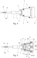
- Figures 4 and 5 are top plan views of a second embodiment of the external end device, the Figure 5 showing the device without removable cover and lid. Further, reference is made to Figures 6 and 7 which show a longitudinal cross-section view and a perspective view, respectively, of the device in Figure 5 , with parts removed for clarity.
- the external end device comprises a biosensor 60 having a sensitive element 62.
- a biosensor 60 having a sensitive element 62.
- the fitting 15 includes, in addition to the two proximal tracts 17, 17, an access conduit 182 to the catheter 3, inside which the biosensor 60 is partially arranged.
- the biosensor 60 comprises an optical fiber 61 at the end of which the sensitive element 62 is arranged.
- the optical fiber 61 is inserted through the access conduit 182.
- An optical system 63 is connected to the optical fiber 61.
- the biosensor 60 is able to detect an analyte sought in the blood thanks to the optical reaction of its sensitive element according to known techniques.
- a detection and transmission system 64 of what has been revealed is also provided.
- the detection and transmission system 64 is a microprocessor which manages signal processing, mathematical manipulation of the same and data storage.
- the detection and transmission system 64 can be in physical or wireless connection.
- the optical system 63 includes a variable wavelength light source that allows various substances dissolved in the blood, that have a different level of reactivity to the wavelength of the light supplied, to be scanned.
- WO 2006/044973 describes an optical fiber suitable for detecting the concentration of analytes, in particular the concentration of glucose in the blood of a patient.
- Figure 3 and Figures 8 and 9 show an exploded longitudinal cross-section view and an exploded longitudinal cross-section view in assembled condition, respectively, along only one flow line of the piercing and connecting conduit in Figure 3 .
- the piercing and connecting conduit 24 comprises, starting distally, a pair of rigid pipes 25, 25 mounted on respective clamps 26, 26.
- Each clamp 26 comprises a central body 27 centrally perforated in order to create a connection between the rigid pipe 25 and a joint 28 located in the central body 27 on the opposite side to the rigid pipe 25.
- gripper arms 29, 29 which distally have a hook 30 for retaining the casing 4.
- the gripper arms 29, 29 are sized so as to engage, on opposite sides to the central body 27, the recesses 23 made in the removable cover 6 and in the base 5. A stable connection of the piercing and connecting conduit 24 to the casing 4 is thus obtained, and therefore to the flow lines of the treatment equipment.
- a gripping lever 31 suitably knurled externally.
- a distal end 320 of an elastic pipe 32 which, at its proximal end 321, is joined to a respective lock element, such as a luer lock, indicated as 33, for an attachment to the flow lines.
- An occlusion clip 34 is positioned on each elastic pipe 32.
- a piercing member 35 for each flow line completes the piercing and connecting conduit 24.
- Each piercing member 35 has a needle 36 and an internally hollow head 37 to close on the lock element 33.
- Figure 8 shows, for simplicity, a single piercing and connecting conduit 24 in which the clamp 26 is connected to the elastic pipe 32, which, after the insertion of the occlusion clip 34, is, in turn, connected to the lock element 33.
- the piercing member 35 is shown separate.
- the piercing and connecting conduit 24, once completely assembled, is approached to the external end device so that the tip of each needle 36, passing through the lock element 33, the elastic pipe 32, the joint 28, the central body 27 of the clamp 26, and the rigid pipe 25, pierce the cap 20 located inside the nozzle chamber 191 of the through septum 19.
- the gripper arms 29, 29 engage the nozzles of the through septa 19 with the hooks 30, each cap 20 is pierced and inside it passes a rigid pipe 25, coaxial to the needle 36.
- a connection is created between the flow lines of the treatment apparatus and the nozzles 190, 190, when the piercing members 35, 35 are extracted and the lock elements 33, 33 are connected to the flow lines of the hemodialysis treatment apparatus.
- the occlusion clips 34, 34 which were closed on the elastic pipes 32, 32 before the insertion of the piercing members 35, 35, can open and the treatment can begin.
- the occlusion clips 34, 34 are closed, and the piercing and connecting conduit 24 is extracted from the external end device 1.
- the rigid pipes 25, 25 come out of the respective caps 20 which close hermetically to their exit. In this way the leakage of blood is prevented, and the envelope 4 of the external end device 1 can be closed with the antiseptic sponge 21 and the lid 10.
- a method for connecting the external end device to the flow lines of a treatment equipment comprises the following steps:
- the external end device according to the present invention has performances and efficiency close to those described in US 9,295,773 B2 , but with the advantage that the patient's skin must not be pierced at each connection with the treatment equipment.
- the performance is guaranteed by the hermetic seal of the envelope 4 and by the minimization of the patient's blood contact with the outside with a consequent decrease in the dangers of infection.
Landscapes
- Health & Medical Sciences (AREA)
- Heart & Thoracic Surgery (AREA)
- Life Sciences & Earth Sciences (AREA)
- Animal Behavior & Ethology (AREA)
- Engineering & Computer Science (AREA)
- Anesthesiology (AREA)
- Biomedical Technology (AREA)
- Hematology (AREA)
- Veterinary Medicine (AREA)
- Vascular Medicine (AREA)
- General Health & Medical Sciences (AREA)
- Public Health (AREA)
- Cardiology (AREA)
- Pulmonology (AREA)
- External Artificial Organs (AREA)
- Infusion, Injection, And Reservoir Apparatuses (AREA)
- Measurement Of The Respiration, Hearing Ability, Form, And Blood Characteristics Of Living Organisms (AREA)
- Media Introduction/Drainage Providing Device (AREA)
Claims (11)
- Dispositif d'extrémité externe adapté pour être connecté, d'un côté, à au moins un cathéter (3), sur lequel un manchon sous-cutané (9) est appliqué, et, de l'autre côté, à un couvercle (10), ou alternativement à des conduites d'écoulement d'un équipement de traitement, le dispositif d'extrémité externe comprenant :- un carter (4), incluant une base (5) délimitée par une pluralité de parois latérales (50), dans laquelle se trouvent une ouverture distale (12) et une paire d'ouvertures proximales (13, 13) par rapport auxdites conduites d'écoulement, et un couvercle amovible (6) sur les parois latérales (50),- un raccord (15) logé dans le carter (4) et ayant au moins une partie distale (16) qui s'engage dans le au moins un cathéter (3), et deux tractus proximaux (17, 17), et- une paire de tuyaux incurvés (18, 18) ayant chacun une extrémité distale (180) insérée sur le tractus proximal (17) respectif du raccord (15), et une extrémité proximale (181), dans lequel le dispositif d'extrémité externe comprend en outre :- une paire de buses (190, 190) équipées de chambres de buse (191, 191) et insérées dans l'extrémité proximale (181, 181) des tuyaux incurvés (18, 18), à l'intérieur de chaque chambre de buse (191) étant un capuchon (20) qui est adapté pour fermer hermétiquement la buse (190) et pouvant être percé de manière réversible, et- un conduit de perçage et de connexion (24) conçu pour percer de manière réversible le capuchon (20) et pour connecter la paire de buses (190, 190) aux conduites d'écoulement de l'équipement de traitement.
- Dispositif selon la revendication 1, dans lequel le couvercle (10) comporte des saillies distales (22, 22), et la base (5) du carter (4) et le couvercle amovible (6) comportent des évidements (23), dans lesquels les saillies distales (22, 22) du couvercle (10) peuvent s'engager en fermant le dispositif avec l'interposition d'une éponge antiseptique (21) entre les chambres de buse (191, 191) fermées avec les capuchons (20) et le couvercle (10).
- Dispositif selon la revendication 1, dans lequel l'ouverture distale (12) et les ouvertures proximales (13, 13) sont délimitées sur trois côtés par des rainures appropriées pour constituer des guides pour insérer des septums, un septum perforé (14) pour le passage du au moins un cathéter (3) et sa fixation au raccord (15) étant reçus dans l'ouverture distale (12), et une paire de septums (19, 19) logeant la paire de chambres de buse (191, 191) étant reçue dans les ouvertures proximales (13, 13) respectives.
- Dispositif selon la revendication 1, dans lequel le conduit de perçage et de connexion (24) comprend en lignes parallèles, à partir d'une extrémité distale du conduit de perçage et de connexion (24) :- une paire de pinces (26, 26), chaque pince (26) ayant un corps central (27) perforé au centre en ligne, un tuyau rigide (25) destiné à être relié à une buse (190) respective dans le septum (19), et un joint (28) situé dans le corps central (27) du côté opposé du tuyau rigide (25),- une paire de tuyaux élastiques (32, 32), chaque tuyau élastique (32) ayant une extrémité distale (320), insérée sur le joint (28), et une extrémité proximale (321),- une paire d'éléments de verrouillage (33, 33), chaque élément de verrouillage (33) étant relié, d'un côté, à l'extrémité proximale (321) du tuyau élastique (32) et, de l'autre côté, à la connexion aux conduites d'écoulement de l'équipement de traitement,- une paire de pinces d'occlusion (34, 34), chaque pince d'occlusion (34) étant positionnée autour de chaque tuyau élastique (32), et- une paire d'éléments de perçage (35, 35), chaque élément de perçage (35) ayant une aiguille (36) et une tête (37) creuse à l'intérieur pour se fermer sur l'élément de verrouillage (33), l'aiguille (36) traversant l'élément de verrouillage (33), le tuyau élastique (32), la pince (26), pour sortir de l'extrémité distale du tuyau rigide (25).
- Dispositif selon la revendication 4, dans lequel la base (5) du carter (4) et le couvercle amovible (6) comportent des évidements (23), et la paire de pinces (26, 26) a, sur des côtés opposés au corps central (27), des bras de préhension (29, 29) équipés distalement de crochets (30, 30) respectifs appropriés pour engager lesdits évidements (23) pour la connexion stable dudit conduit de perçage et de connexion (24) au carter (4).
- Dispositif selon la revendication 1, dans lequel le capuchon (20) pouvant être percé de manière réversible est en silicone.
- Dispositif selon la revendication 1, dans lequel le raccord (15) inclut, en plus des deux tractus proximaux (17, 17), un conduit d'accès (182) au cathéter (3), et un biocapteur (60) est partiellement inséré dans le conduit d'accès (182), le biocapteur (60) ayant un élément sensible (62) capable de réagir de manière optique avec le sang recouvrant le cathéter (3).
- Dispositif selon la revendication 7, dans lequel le biocapteur (60) comprend un élément sensible (62) fixé à une fibre optique (61) reçue dans le cathéter (3) à travers le conduit d'accès (182), un système optique (63) connecté à la fibre optique (61) et incluant une source de lumière ayant une longueur d'onde variable, et un système de détection, de stockage et de transmission (64).
- Dispositif selon la revendication 8, dans lequel le cathéter (3) a une fenêtre transparente (300) faisant face à l'élément sensible (62) du biocapteur (60).
- Dispositif selon la revendication 1, dans lequel le couvercle amovible (6) est fixé sur les parois latérales (50) au moyen de vis (7) avec l'interposition d'un joint (11).
- Méthode de connexion d'un dispositif d'extrémité externe à des conduites d'écoulement d'un équipement de traitement, le dispositif d'extrémité externe comprenant :- un carter (4), incluant une base (5) et un couvercle amovible (6), et un couvercle (10) avec interposition d'une éponge antiseptique (21),- une paire de buses (190, 190) équipées de chambres de buse (191, 191) et reliées à une extrémité distale à au moins un cathéter (3) par l'intermédiaire d'un raccord (15), à l'intérieur de chaque chambre de buse (191) étant un capuchon (20) approprié pour fermer hermétiquement la buse (190) qui est perforable de manière réversible,- un conduit de perçage et de connexion (24) adapté pour percer de manière réversible le capuchon (20) et pour connecter la paire de buses (190, 190) aux conduites d'écoulement de l'équipement de traitement, le conduit de perçage et de connexion (24) comprenant en lignes parallèles, à partir d'une extrémité distale du conduit de perçage et de connexion :comprenant les étapes suivantes:- une paire de pinces (26, 26) pour accrocher le conduit de perçage et de connexion au carter (4),- une paire de tuyaux élastiques (32, 32),- une paire d'éléments de verrouillage (33, 33), connectables aux conduites d'écoulement de l'équipement de traitement,- une paire de pinces d'occlusion (34, 34), positionnées autour de chaque tuyau élastique (32), et- une paire d'éléments de perçage (35, 35), chaque élément de perçage (35) ayant une aiguille (36) et une tête (37) qui est creuse à l'intérieur pour se fermer sur l'élément de verrouillage (33), l'aiguille (36) traversant l'élément de verrouillage (33), le tuyau élastique (32), la pince (26), pour sortir de l'extrémité distale du tuyau rigide (25),- retirer le couvercle (10) et l'éponge antiseptique (21) du carter (4) ;- assembler en ligne le conduit de perçage et de connexion (24) en joignant la paire de pinces (26, 26), la paire de tuyaux élastiques (32, 32), la paire de pinces d'occlusion (34, 34) autour des tuyaux élastiques (32) respectifs, la paire d'éléments de verrouillage (33, 33) et la paire d'éléments de perçage (35, 35) ;- s'approcher du conduit de perçage et de connexion (24) monté coaxialement à la paire de buses (190, 190) jusqu'au couplage de la paire de pinces (26) au carter (4) avec pour conséquence un perçage réversible des capuchons (20) à l'intérieur des chambres de buses (191, 191) ;- retirer la paire d'éléments de perçage (35) du conduit de perçage et de connexion (24) avec fermeture simultanée de la paire de pinces d'occlusion (34, 34) autour de la paire de tuyaux élastiques (32, 32) ; et- connecter la paire d'éléments de verrouillage (33, 33) aux conduites d'écoulement de l'équipement de traitement.
Applications Claiming Priority (3)
| Application Number | Priority Date | Filing Date | Title |
|---|---|---|---|
| IT102020000000565A IT202000000565A1 (it) | 2020-01-14 | 2020-01-14 | Dispositivo terminale esterno e metodo per il suo collegamento a linee di flusso |
| IT102020000000568A IT202000000568A1 (it) | 2020-01-14 | 2020-01-14 | Dispositivo terminale esterno atto a rivelare la concentrazione di analiti |
| PCT/IB2021/050232 WO2021144716A1 (fr) | 2020-01-14 | 2021-01-13 | Dispositif d'extrémité externe et méthode pour sa connexion à des conduites d'écoulement |
Publications (3)
| Publication Number | Publication Date |
|---|---|
| EP4090396A1 EP4090396A1 (fr) | 2022-11-23 |
| EP4090396C0 EP4090396C0 (fr) | 2024-01-10 |
| EP4090396B1 true EP4090396B1 (fr) | 2024-01-10 |
Family
ID=74215989
Family Applications (1)
| Application Number | Title | Priority Date | Filing Date |
|---|---|---|---|
| EP21701595.7A Active EP4090396B1 (fr) | 2020-01-14 | 2021-01-13 | Dispositif d'extrémité externe et méthode pour sa connexion à des conduites d'écoulement |
Country Status (6)
| Country | Link |
|---|---|
| US (1) | US20230044667A1 (fr) |
| EP (1) | EP4090396B1 (fr) |
| JP (1) | JP7608477B2 (fr) |
| CN (1) | CN115103697B (fr) |
| BR (1) | BR112022013949A2 (fr) |
| WO (1) | WO2021144716A1 (fr) |
Family Cites Families (31)
| Publication number | Priority date | Publication date | Assignee | Title |
|---|---|---|---|---|
| US4755173A (en) * | 1986-02-25 | 1988-07-05 | Pacesetter Infusion, Ltd. | Soft cannula subcutaneous injection set |
| US4874369A (en) * | 1987-07-27 | 1989-10-17 | Baxter International Inc. | Self-priming injection site with check valve |
| US5290222A (en) * | 1991-10-15 | 1994-03-01 | Jiyu Feng | Injection port connector with rotatable locking lug |
| US5386735A (en) * | 1992-12-15 | 1995-02-07 | Langdon Medical, Inc. | Apparatus for collecting a fluid sample from a patient and container for storing the same |
| US5453576A (en) * | 1994-10-24 | 1995-09-26 | Transonic Systems Inc. | Cardiovascular measurements by sound velocity dilution |
| US6206851B1 (en) * | 1995-06-07 | 2001-03-27 | Biolink Corporation | Hemodialysis access apparatus |
| US6013058A (en) * | 1996-06-12 | 2000-01-11 | Biolink Corporation | Device for subcutaneous accessibility |
| US6007516A (en) * | 1997-01-21 | 1999-12-28 | Vasca, Inc. | Valve port and method for vascular access |
| US6228060B1 (en) * | 1998-09-02 | 2001-05-08 | Becton, Dickinson And Company | Blood seal having a spring-biased septum |
| US7500949B2 (en) * | 2002-03-01 | 2009-03-10 | Medtronic Minimed, Inc. | Multilumen catheter |
| EP1523350B1 (fr) * | 2002-07-19 | 2011-04-13 | Baxter International Inc. | Systeme de dialyse peritoneale |
| US7787923B2 (en) * | 2003-11-26 | 2010-08-31 | Becton, Dickinson And Company | Fiber optic device for sensing analytes and method of making same |
| US7347853B2 (en) * | 2004-05-12 | 2008-03-25 | C. R. Bard, Inc. | Catheter with removable extension |
| US7314238B2 (en) * | 2004-05-28 | 2008-01-01 | American Sterilizer Company | Fluid connection |
| US20090156975A1 (en) * | 2007-11-30 | 2009-06-18 | Mark Ries Robinson | Robust System and Methods for Blood Access |
| CN100502778C (zh) * | 2005-11-24 | 2009-06-24 | 复旦大学附属中山医院 | 在体实时光敏感血液钠离子传感器及其制备方法 |
| US8133194B2 (en) * | 2006-02-22 | 2012-03-13 | Henry Ford Health System | System and method for delivery of regional citrate anticoagulation to extracorporeal blood circuits |
| US9855410B2 (en) * | 2007-05-01 | 2018-01-02 | St. Jude Medical, Atrial Fibrillation Division, Inc. | Optic-based contact sensing assembly and system |
| DE102007025900A1 (de) * | 2007-06-01 | 2008-12-04 | Rouska Nenov | Verschlußvorrichtung für Venenverweilkanülen |
| IT1394269B1 (it) * | 2009-06-16 | 2012-06-06 | Grandolfo | Dispositivo terminale per catetere permanente per emodialisi |
| EP2286849A1 (fr) * | 2009-08-21 | 2011-02-23 | Cendres & Métaux S.A. | Accès vasculaire implantable |
| US10711930B2 (en) * | 2009-12-09 | 2020-07-14 | Nordson Corporation | Releasable connection assembly |
| AU2011326519A1 (en) * | 2010-11-09 | 2013-05-30 | Hans-Dietrich Polaschegg | Hemodialysis access system |
| ITRM20120013A1 (it) * | 2012-01-16 | 2013-07-17 | Nicola Grandolfo | Dispositivo terminale esterno per cateteri permanenti atto all'isolamento di un flusso liquido |
| US20130303986A1 (en) * | 2012-05-14 | 2013-11-14 | Richard V. Penalosa, JR. | Vascular Access Catheter Anchor and Access Valve |
| EP3218026A4 (fr) * | 2014-11-13 | 2018-09-12 | PAVmed, Inc. | Orifices de perfusion intra-osseuse et procédés d'utilisation |
| US20190111235A1 (en) * | 2016-04-27 | 2019-04-18 | Avasys, Llc | Catheter hub with removable extensions |
| US11065418B1 (en) * | 2016-10-17 | 2021-07-20 | Srs Medical Systems, Llc | Bladder storage anomaly assessment |
| KR102004615B1 (ko) * | 2017-11-03 | 2019-10-04 | 가톨릭대학교 산학협력단 | 혈액투석용 혈관 접속 장치 |
| WO2021046365A1 (fr) * | 2019-09-06 | 2021-03-11 | Adventist Health System/Sunbelt, Inc. | Cathéter de dialyse perfectionné à capteur de pression |
| US11707604B2 (en) * | 2020-03-31 | 2023-07-25 | Becton, Dickinson And Company | Primer for intravenous catheter systems |
-
2021
- 2021-01-13 CN CN202180009360.6A patent/CN115103697B/zh active Active
- 2021-01-13 US US17/758,802 patent/US20230044667A1/en active Pending
- 2021-01-13 WO PCT/IB2021/050232 patent/WO2021144716A1/fr not_active Ceased
- 2021-01-13 JP JP2022567707A patent/JP7608477B2/ja active Active
- 2021-01-13 BR BR112022013949A patent/BR112022013949A2/pt unknown
- 2021-01-13 EP EP21701595.7A patent/EP4090396B1/fr active Active
Also Published As
| Publication number | Publication date |
|---|---|
| EP4090396A1 (fr) | 2022-11-23 |
| WO2021144716A1 (fr) | 2021-07-22 |
| CN115103697A (zh) | 2022-09-23 |
| EP4090396C0 (fr) | 2024-01-10 |
| JP2023512598A (ja) | 2023-03-27 |
| US20230044667A1 (en) | 2023-02-09 |
| JP7608477B2 (ja) | 2025-01-06 |
| CN115103697B (zh) | 2025-03-11 |
| BR112022013949A2 (pt) | 2022-10-11 |
Similar Documents
| Publication | Publication Date | Title |
|---|---|---|
| US20230241313A1 (en) | Infusion and blood collection device | |
| US10596315B2 (en) | Systems and methods for delivering a fluid to a patient with reduced contamination | |
| JP4866365B2 (ja) | 雌コネクタと連結するための自己封止式の雄コネクタ、雌ルアー・コネクタと連結するための自己封止式の雄ルアー・コネクタ、及び雄コネクタを雌コネクタと係合する方法 | |
| CA2200526A1 (fr) | Adaptateur a valve pour instruments medicaux d'acces au besoin a des fins medicales | |
| EP4142625A1 (fr) | Système d'insertion de canule et ses procédés d'utilisation | |
| JP2002000722A (ja) | チューブ、継管具、接続口作製具および継管システム | |
| EP0549730B1 (fr) | Point de prise d'echantillon avec raccord sans aiguille | |
| EP4090396B1 (fr) | Dispositif d'extrémité externe et méthode pour sa connexion à des conduites d'écoulement | |
| CN114929109A (zh) | 输注和血液采集装置和方法 | |
| EP1834657A1 (fr) | Support pour traitement medical | |
| WO2020066781A1 (fr) | Ensemble cathéter | |
| CN210301906U (zh) | 一种双排气穿刺防回血留置输液针 | |
| AU673839B2 (en) | Sealable external access catheter | |
| KR20040107920A (ko) | 1회용 혈관 수지침 |
Legal Events
| Date | Code | Title | Description |
|---|---|---|---|
| STAA | Information on the status of an ep patent application or granted ep patent |
Free format text: STATUS: UNKNOWN |
|
| STAA | Information on the status of an ep patent application or granted ep patent |
Free format text: STATUS: THE INTERNATIONAL PUBLICATION HAS BEEN MADE |
|
| PUAI | Public reference made under article 153(3) epc to a published international application that has entered the european phase |
Free format text: ORIGINAL CODE: 0009012 |
|
| STAA | Information on the status of an ep patent application or granted ep patent |
Free format text: STATUS: REQUEST FOR EXAMINATION WAS MADE |
|
| 17P | Request for examination filed |
Effective date: 20220721 |
|
| AK | Designated contracting states |
Kind code of ref document: A1 Designated state(s): AL AT BE BG CH CY CZ DE DK EE ES FI FR GB GR HR HU IE IS IT LI LT LU LV MC MK MT NL NO PL PT RO RS SE SI SK SM TR |
|
| DAV | Request for validation of the european patent (deleted) | ||
| DAX | Request for extension of the european patent (deleted) | ||
| GRAP | Despatch of communication of intention to grant a patent |
Free format text: ORIGINAL CODE: EPIDOSNIGR1 |
|
| STAA | Information on the status of an ep patent application or granted ep patent |
Free format text: STATUS: GRANT OF PATENT IS INTENDED |
|
| INTG | Intention to grant announced |
Effective date: 20230918 |
|
| GRAS | Grant fee paid |
Free format text: ORIGINAL CODE: EPIDOSNIGR3 |
|
| GRAA | (expected) grant |
Free format text: ORIGINAL CODE: 0009210 |
|
| STAA | Information on the status of an ep patent application or granted ep patent |
Free format text: STATUS: THE PATENT HAS BEEN GRANTED |
|
| AK | Designated contracting states |
Kind code of ref document: B1 Designated state(s): AL AT BE BG CH CY CZ DE DK EE ES FI FR GB GR HR HU IE IS IT LI LT LU LV MC MK MT NL NO PL PT RO RS SE SI SK SM TR |
|
| REG | Reference to a national code |
Ref country code: GB Ref legal event code: FG4D |
|
| REG | Reference to a national code |
Ref country code: CH Ref legal event code: EP |
|
| REG | Reference to a national code |
Ref country code: DE Ref legal event code: R096 Ref document number: 602021008525 Country of ref document: DE |
|
| REG | Reference to a national code |
Ref country code: IE Ref legal event code: FG4D |
|
| U01 | Request for unitary effect filed |
Effective date: 20240111 |
|
| U07 | Unitary effect registered |
Designated state(s): AT BE BG DE DK EE FI FR IT LT LU LV MT NL PT SE SI Effective date: 20240125 |
|
| U20 | Renewal fee for the european patent with unitary effect paid |
Year of fee payment: 4 Effective date: 20240216 |
|
| PG25 | Lapsed in a contracting state [announced via postgrant information from national office to epo] |
Ref country code: IS Free format text: LAPSE BECAUSE OF FAILURE TO SUBMIT A TRANSLATION OF THE DESCRIPTION OR TO PAY THE FEE WITHIN THE PRESCRIBED TIME-LIMIT Effective date: 20240510 |
|
| PG25 | Lapsed in a contracting state [announced via postgrant information from national office to epo] |
Ref country code: GR Free format text: LAPSE BECAUSE OF FAILURE TO SUBMIT A TRANSLATION OF THE DESCRIPTION OR TO PAY THE FEE WITHIN THE PRESCRIBED TIME-LIMIT Effective date: 20240411 |
|
| PG25 | Lapsed in a contracting state [announced via postgrant information from national office to epo] |
Ref country code: RS Free format text: LAPSE BECAUSE OF FAILURE TO SUBMIT A TRANSLATION OF THE DESCRIPTION OR TO PAY THE FEE WITHIN THE PRESCRIBED TIME-LIMIT Effective date: 20240410 Ref country code: HR Free format text: LAPSE BECAUSE OF FAILURE TO SUBMIT A TRANSLATION OF THE DESCRIPTION OR TO PAY THE FEE WITHIN THE PRESCRIBED TIME-LIMIT Effective date: 20240110 |
|
| PG25 | Lapsed in a contracting state [announced via postgrant information from national office to epo] |
Ref country code: ES Free format text: LAPSE BECAUSE OF FAILURE TO SUBMIT A TRANSLATION OF THE DESCRIPTION OR TO PAY THE FEE WITHIN THE PRESCRIBED TIME-LIMIT Effective date: 20240110 |
|
| PG25 | Lapsed in a contracting state [announced via postgrant information from national office to epo] |
Ref country code: RS Free format text: LAPSE BECAUSE OF FAILURE TO SUBMIT A TRANSLATION OF THE DESCRIPTION OR TO PAY THE FEE WITHIN THE PRESCRIBED TIME-LIMIT Effective date: 20240410 Ref country code: NO Free format text: LAPSE BECAUSE OF FAILURE TO SUBMIT A TRANSLATION OF THE DESCRIPTION OR TO PAY THE FEE WITHIN THE PRESCRIBED TIME-LIMIT Effective date: 20240410 Ref country code: IS Free format text: LAPSE BECAUSE OF FAILURE TO SUBMIT A TRANSLATION OF THE DESCRIPTION OR TO PAY THE FEE WITHIN THE PRESCRIBED TIME-LIMIT Effective date: 20240510 Ref country code: HR Free format text: LAPSE BECAUSE OF FAILURE TO SUBMIT A TRANSLATION OF THE DESCRIPTION OR TO PAY THE FEE WITHIN THE PRESCRIBED TIME-LIMIT Effective date: 20240110 Ref country code: GR Free format text: LAPSE BECAUSE OF FAILURE TO SUBMIT A TRANSLATION OF THE DESCRIPTION OR TO PAY THE FEE WITHIN THE PRESCRIBED TIME-LIMIT Effective date: 20240411 Ref country code: ES Free format text: LAPSE BECAUSE OF FAILURE TO SUBMIT A TRANSLATION OF THE DESCRIPTION OR TO PAY THE FEE WITHIN THE PRESCRIBED TIME-LIMIT Effective date: 20240110 |
|
| PG25 | Lapsed in a contracting state [announced via postgrant information from national office to epo] |
Ref country code: PL Free format text: LAPSE BECAUSE OF FAILURE TO SUBMIT A TRANSLATION OF THE DESCRIPTION OR TO PAY THE FEE WITHIN THE PRESCRIBED TIME-LIMIT Effective date: 20240110 |
|
| PG25 | Lapsed in a contracting state [announced via postgrant information from national office to epo] |
Ref country code: PL Free format text: LAPSE BECAUSE OF FAILURE TO SUBMIT A TRANSLATION OF THE DESCRIPTION OR TO PAY THE FEE WITHIN THE PRESCRIBED TIME-LIMIT Effective date: 20240110 |
|
| REG | Reference to a national code |
Ref country code: DE Ref legal event code: R097 Ref document number: 602021008525 Country of ref document: DE |
|
| PG25 | Lapsed in a contracting state [announced via postgrant information from national office to epo] |
Ref country code: SM Free format text: LAPSE BECAUSE OF FAILURE TO SUBMIT A TRANSLATION OF THE DESCRIPTION OR TO PAY THE FEE WITHIN THE PRESCRIBED TIME-LIMIT Effective date: 20240110 |
|
| PG25 | Lapsed in a contracting state [announced via postgrant information from national office to epo] |
Ref country code: CZ Free format text: LAPSE BECAUSE OF FAILURE TO SUBMIT A TRANSLATION OF THE DESCRIPTION OR TO PAY THE FEE WITHIN THE PRESCRIBED TIME-LIMIT Effective date: 20240110 |
|
| PG25 | Lapsed in a contracting state [announced via postgrant information from national office to epo] |
Ref country code: SK Free format text: LAPSE BECAUSE OF FAILURE TO SUBMIT A TRANSLATION OF THE DESCRIPTION OR TO PAY THE FEE WITHIN THE PRESCRIBED TIME-LIMIT Effective date: 20240110 |
|
| PG25 | Lapsed in a contracting state [announced via postgrant information from national office to epo] |
Ref country code: SM Free format text: LAPSE BECAUSE OF FAILURE TO SUBMIT A TRANSLATION OF THE DESCRIPTION OR TO PAY THE FEE WITHIN THE PRESCRIBED TIME-LIMIT Effective date: 20240110 Ref country code: SK Free format text: LAPSE BECAUSE OF FAILURE TO SUBMIT A TRANSLATION OF THE DESCRIPTION OR TO PAY THE FEE WITHIN THE PRESCRIBED TIME-LIMIT Effective date: 20240110 Ref country code: RO Free format text: LAPSE BECAUSE OF FAILURE TO SUBMIT A TRANSLATION OF THE DESCRIPTION OR TO PAY THE FEE WITHIN THE PRESCRIBED TIME-LIMIT Effective date: 20240110 Ref country code: CZ Free format text: LAPSE BECAUSE OF FAILURE TO SUBMIT A TRANSLATION OF THE DESCRIPTION OR TO PAY THE FEE WITHIN THE PRESCRIBED TIME-LIMIT Effective date: 20240110 |
|
| PLBE | No opposition filed within time limit |
Free format text: ORIGINAL CODE: 0009261 |
|
| STAA | Information on the status of an ep patent application or granted ep patent |
Free format text: STATUS: NO OPPOSITION FILED WITHIN TIME LIMIT |
|
| 26N | No opposition filed |
Effective date: 20241011 |
|
| U20 | Renewal fee for the european patent with unitary effect paid |
Year of fee payment: 5 Effective date: 20250131 |
|
| PGFP | Annual fee paid to national office [announced via postgrant information from national office to epo] |
Ref country code: CH Payment date: 20250204 Year of fee payment: 5 |
|
| PG25 | Lapsed in a contracting state [announced via postgrant information from national office to epo] |
Ref country code: CY Free format text: LAPSE BECAUSE OF FAILURE TO SUBMIT A TRANSLATION OF THE DESCRIPTION OR TO PAY THE FEE WITHIN THE PRESCRIBED TIME-LIMIT; INVALID AB INITIO Effective date: 20210113 |
|
| PG25 | Lapsed in a contracting state [announced via postgrant information from national office to epo] |
Ref country code: HU Free format text: LAPSE BECAUSE OF FAILURE TO SUBMIT A TRANSLATION OF THE DESCRIPTION OR TO PAY THE FEE WITHIN THE PRESCRIBED TIME-LIMIT; INVALID AB INITIO Effective date: 20210113 |
|
| PG25 | Lapsed in a contracting state [announced via postgrant information from national office to epo] |
Ref country code: TR Free format text: LAPSE BECAUSE OF FAILURE TO SUBMIT A TRANSLATION OF THE DESCRIPTION OR TO PAY THE FEE WITHIN THE PRESCRIBED TIME-LIMIT Effective date: 20240110 |
|
| U20 | Renewal fee for the european patent with unitary effect paid |
Year of fee payment: 6 Effective date: 20260129 |
|
| PGFP | Annual fee paid to national office [announced via postgrant information from national office to epo] |
Ref country code: GB Payment date: 20260128 Year of fee payment: 6 |
|
| PGFP | Annual fee paid to national office [announced via postgrant information from national office to epo] |
Ref country code: MC Payment date: 20260128 Year of fee payment: 6 |
|
| PGFP | Annual fee paid to national office [announced via postgrant information from national office to epo] |
Ref country code: IE Payment date: 20260128 Year of fee payment: 6 |