EP4090468B1 - Dispositif et procédé pour broyer une matière de charge - Google Patents
Dispositif et procédé pour broyer une matière de charge Download PDFInfo
- Publication number
- EP4090468B1 EP4090468B1 EP21700191.6A EP21700191A EP4090468B1 EP 4090468 B1 EP4090468 B1 EP 4090468B1 EP 21700191 A EP21700191 A EP 21700191A EP 4090468 B1 EP4090468 B1 EP 4090468B1
- Authority
- EP
- European Patent Office
- Prior art keywords
- roller
- axis
- force
- loose
- fixed
- Prior art date
- Legal status (The legal status is an assumption and is not a legal conclusion. Google has not performed a legal analysis and makes no representation as to the accuracy of the status listed.)
- Active
Links
Images


Classifications
-
- B—PERFORMING OPERATIONS; TRANSPORTING
- B02—CRUSHING, PULVERISING, OR DISINTEGRATING; PREPARATORY TREATMENT OF GRAIN FOR MILLING
- B02C—CRUSHING, PULVERISING, OR DISINTEGRATING IN GENERAL; MILLING GRAIN
- B02C4/00—Crushing or disintegrating by roller mills
- B02C4/02—Crushing or disintegrating by roller mills with two or more rollers
-
- B—PERFORMING OPERATIONS; TRANSPORTING
- B02—CRUSHING, PULVERISING, OR DISINTEGRATING; PREPARATORY TREATMENT OF GRAIN FOR MILLING
- B02C—CRUSHING, PULVERISING, OR DISINTEGRATING IN GENERAL; MILLING GRAIN
- B02C4/00—Crushing or disintegrating by roller mills
- B02C4/28—Details
- B02C4/32—Adjusting, applying pressure to, or controlling the distance between, milling members
Definitions
- the invention relates to a device and a method for grinding feedstock, in particular a device designed as a roller mill, with a fixed roller and a loose roller, the loose roller being displaceable relative to the fixed roller.
- the rollers can be mounted and supported on a frame, in particular together on a common frame.
- roller press devices designed as material bed roller mills for feedstock in the form of minerals or mining material are affected.
- so-called roller presses are also affected, for example with a drive power in the range of at least 200 KW to 5,000 KW.
- the invention relates to a device and a method according to the preamble of the respective independent or subordinate claim.
- Roller presses also generally called “roller presses”
- the rollers are usually mounted in a fixed position on the one hand and in a translationally displaceable position on the other.
- a hydraulic force exerted on the loosely mounted loose roller in the direction of the grinding gap causes a translational displacement relative to the contact point of the rollers, or a force is applied in the grinding gap.
- the loose roller is subjected to translational pressure at at least two points, also in order to prevent torques.
- roller presses usually have a fixed roller and a loose roller, whereby the loose roller can be moved translationally relative to the fixed roller, and whereby the rollers are mounted and supported in a frame.
- a lower and an upper frame part are provided, on each of which a (translational) plain bearing is provided for the loose roller.
- additional stabilizing actuators are often also required.
- roller presses are relatively large and the forces and moments or impulses are large, it is not trivial from a structural point of view to design a roller press for the widest possible range of operating conditions or different materials.
- the question of how reaction forces can or should be transferred from the rollers to the frame and into the foundation requires great engineering effort.
- the design requirements are particularly high with regard to high continuous loads.
- the roller press must also be as robust as possible with regard to misalignment, overload or similar negative effects. For example, exact adjustability and exact relative alignment of the roller axes therefore also remain an important factor for many roller types when selecting an advantageous overall design concept.
- the axes of the roller press must be able to be positioned as precisely as possible within a minimally narrow tolerance range, especially relative to one another.
- a high dynamic continuous load in combination with narrow tolerance ranges for the relative position of the rollers justifies high design requirements.
- the drive power of the roller presses which tend to be large and heavy, is in the range of 2x 150-200 KW, for example, i.e. a total of 350 KW, but can also be significantly larger, for example 2x 3000 KW.
- the spatial dimensions in the three spatial directions can be, for example, two to four meters each. However, significantly larger or smaller designs can also be implemented or are in use; in particular, scaling can be carried out individually for each application depending on the material to be treated.
- the present invention is largely scalable independently of the respective roller type; the present invention is particularly advantageous in the case of comparatively large roller presses.
- EN 10 2015 114 992 A2 describes a roller press for grinding material to be ground, wherein the rollers or cylinders are mounted in such a way that a change of the rollers can be simplified, in particular by a line of action of a resulting operating force extending in a half-space within a supporting structure, wherein a/the idler roller cooperates with pivoting devices which pivot as a lever on both sides about a pivot bearing.
- the idler rollers of these roller presses are therefore not mounted purely in a translational manner, but can be pivoted.
- a machine having a drive roller and a driven roller connected to a central portion of a circular connecting wire.
- the ends of the drive roller and the driven roller are coaxially connected to an end shaft.
- a swing arm is mounted on a rotating shaft via a swing shaft.
- the rotating shaft is mounted on a swing bearing seat.
- An output shaft is connected to a reduction gear mounted on the swing arm.
- a swing arm pressure plate is connected to an upper portion of a machine frame and fills gas into a compressed air bag.
- the object of the invention is to provide a device and a method with the features described at the outset, with which the grinding of feedstock can be further optimized, or with which individual rollers can be used in combination with one another in a particularly expedient manner for grinding feedstock.
- a roller press device set up for grinding feedstock for example ground material in the form of minerals
- a roller mill specifically as a material bed roller mill
- feedstock for example ground material in the form of minerals
- a roller mill specifically as a material bed roller mill
- a fixedly mounted fixed roller with a roller axis that is mounted at least approximately stationary
- a loosely mounted loose roller with a roller axis that can be arranged in a variable location in a predefinable relative position to the fixed roller
- a frame that supports at least the fixed roller and optionally also the loose roller
- the fixed and loose rollers can be mounted and positioned relative to one another to apply a grinding force (resulting roller force in the grinding gap) and to contact one another at a roller contact point or to define a grinding gap for the feedstock, in particular by means of the force application unit
- the loose roller with the variable-position roller axis is pivotable about a pivot axis in the manner of
- the pivoting bearing of the floating roller also offers great advantages in terms of force introduction and force application, especially with very massive rollers.
- the forces provided especially hydraulic forces
- the amount of force required, and thus ultimately also the energy required can be minimized.
- the entire device can also be designed more slenderly, i.e. with less effort in terms of material, costs and overall weight.
- the hydraulic force to be installed can also be minimized; the effort for hydraulic fittings and pressure-resistant lines and adapters can be noticeably reduced.
- the variable-position roller axis can be pivotally positioned in the grinding gap with a comparatively small actuation force.
- the pivot axis also defines a pivot point for the one-sided lever.
- the stationary roller axis can optionally be/remain completely stationary without any displacement mechanism provided, i.e. for all conceivable operating conditions or operating states.
- a loose roller is understood to be the roller that can be actively positioned relative to the fixed roller and is also mounted so that it can be moved locally for relative displacement.
- a fixed roller is understood to be a roller that is mounted in a fixed position without any local displacement being planned.
- the fixed roller can also be mounted in a swivel bearing.
- the terms chosen here for fixed and loose bearings are independent of any mechanical or kinematic requirements for static/dynamic determination. The terms chosen here serve primarily to illustrate the two different roller types.
- the pivot axis is arranged on the tangent of the fixed roller and the loose roller at the roller contact point, provided that a grinding gap of zero through direct contact of the Fixed roller and the loose roller there is a roller contact point. If the grinding gap is different from zero, the pivot axis is arranged between the tangent of the fixed roller at the intersection of the connecting line between the stationary roller axis and the roller axis that can be arranged at a variable location and the tangent of the loose roller at the intersection of the connecting line between the stationary roller axis and the roller axis that can be arranged at a variable location.
- the tangents in the sense of the invention also includes lying on at least one of the tangents, which results in particular in the special case of a grinding gap of zero, since in this special case both tangents coincide and thus the pivot axis is arranged on both coinciding tangents.
- the pivot axis can lie in particular on the tangent of the fixed roller at the intersection of the connecting line between the stationary roller axis and the roller axis that can be arranged at a variable location, since this would enable a variable grinding gap from zero.
- the grinding gap is small compared to the diameter of the fixed roller and the diameter of the loose roller, so that the assumption of a grinding gap of zero can be within the tolerances.
- the grinding gap can also assume negative values, which are then limited to the maximum depth of engagement of the rollers.
- the arrangement according to the invention also enables the frame to be used in an advantageous manner.
- conventional, proven designs and constructions of the frame can also be implemented for the arrangement according to the invention.
- the arrangement according to the invention is preferably designed for drive powers in the range of at least 200 KW to 5,000 KW.
- the bearings used are designed in particular to absorb and transmit impulses and reaction forces that are exerted on the rollers and bearings by the material to be ground in the form of minerals or stones or the like during grinding. Measures that are advantageous or feasible in terms of plant technology, process technology and construction can be predetermined or restricted by this area of application. The expert must also look for particularly appropriate measures specifically for the desired area of application.
- a (purely) mechanical misalignment suppression can be dispensed with in a roller device according to the invention.
- Hydraulic measures for misalignment suppression can also be dispensed with at least in part.
- the arrangement according to the invention also has the advantage that misalignment can be effectively reduced or even completely avoided thanks to the manner in which the rollers are mounted relative to one another and thanks to a pivoting movement of the idler roller.
- a one-sided lever or a one-sided lever arrangement is an arrangement in which only one end of the lever is pivoted and the lever is arranged on the other side in the pivot bearing.
- the load arm and force arm coincide.
- a one-sided lever only one end of the lever is subjected to force.
- There is only one force application point and pivoting the lever does not lead to a force effect or torque generation at the other end of the lever.
- a pivot bearing is provided at the other end (pivot point) for pivoting the lever around the pivot bearing.
- a point of action or an interaction point or a mechanical interface is arranged on the path between the pivot bearing and the end of the lever. In other words: There is no pivoting counter-movement.
- two ends of a lever are pivoted together, i.e. one end performs a pivoting relative movement and the other end also performs a pivoting relative movement, so that the relative length of the two lever arms is important.
- the force application point is arranged, for example, on a bearing block of the loose roller or between bearing blocks of the loose roller, wherein when a force is applied between the bearing blocks, the bearing blocks are preferably coupled, in particular in such a way that a hydraulic force can be transmitted to the bearing blocks via the coupling.
- Bearing blocks can be, for example, bearing bushes, roller bearings or similar rotary bearing elements.
- the bearing blocks serve in particular to accommodate the bearings and to transmit the reaction forces to the bearings.
- a coupling of two or more bearing blocks is not absolutely necessary. However, if misalignment is to be completely prevented, a coupling of the bearing blocks can be particularly effective.
- the coupling can be realized, for example, by the two bearing blocks and at least one component for the coupling consisting of a cast part.
- the coupling can also be realized by a connection (for example screwed) of a steel tube/steel frame to the bearing blocks.
- the force application point can, for example, be located between the two bearing jewels, or there can be one force application point for each bearing jewel.
- the invention is also based on the concept of ensuring the positioning of a loose roller relative to a fixed roller by means of a one-sided lever arrangement only through translational actuation. Rotatory adjustment movements or, for example, the use of eccentrics are not required. According to the invention, a comparatively slim, simple construction with comparatively few interacting components and few relative movements can therefore be provided. This also makes it easy to adapt or scale the design.
- the terms “fixed” and “loose” refer in particular to an operating state for grinding feedstock.
- the fixed roller is not usually moved during grinding, but can nevertheless be mounted in such a way that the fixed roller can be moved for assembly purposes, for example.
- the loose roller is usually positioned.
- the inventive concept can also be transferred to two rollers that are loosely mounted against each other.
- the roller press device is designed as a material bed roller mill. It has been shown that the advantages according to the invention described here can also be implemented particularly advantageously in a material bed roller mill.
- the distance r Abs between the pivot axis and the connecting line between the stationary roller axis and the positionally variable roller axis along a straight line lying at right angles to the connecting line between the stationary roller axis and the positionally variable roller axis and through the pivot axis corresponds to at least 0.15 times the sum of the radius of the fixed roller r Fixed and the radius of the loose roller r Loose and at most 1 times the sum of the radius of the fixed roller r Fixed and the radius of the loose roller r Los . This results in: 0.15 ⁇ r Firmly + r Come on ⁇ r Section ⁇ 1 ⁇ r Firmly + r Come on
- the distance r Abs between the pivot axis and the connecting line between the stationary roller axis and the positionally variable roller axis corresponds along a line perpendicular to the connecting line between the stationary roller axis and the positionally variable roller axis and the straight line passing through the swivel axis is at least 0.2 times the sum of the radius of the fixed roller r fixed and the radius of the loose roller r loose and at most 0.8 times the sum of the radius of the fixed roller r fixed and the radius of the loose roller r loose .
- the distance r Abs between the pivot axis and the connecting line between the stationary roller axis and the positionally variable roller axis along a straight line lying at right angles to the connecting line between the stationary roller axis and the positionally variable roller axis and through the pivot axis corresponds to at least 0.25 times the sum of the radius of the fixed roller r Fixed and the radius of the loose roller r Loose and at most 0.75 times the sum of the radius of the fixed roller r Fixed and the radius of the loose roller r Loose .
- the distance r Abs between the pivot axis and the connecting line between the stationary roller axis and the roller axis that can be arranged in a variable location along a straight line lying at right angles to the connecting line between the stationary roller axis and the roller axis that can be arranged in a variable location and through the pivot axis corresponds to at least 0.25 times the sum of the radius of the fixed roller r Fixed and the radius of the loose roller r Loose and at most 0.6 times the sum of the radius of the fixed roller r Fixed and the radius of the loose roller r Los . This gives: 0.25 ⁇ r Firmly + r Come on ⁇ r Section ⁇ 0.6 ⁇ r Firmly + r Come on
- the distance between the pivot axis and the force application point corresponds to 1 to 5 times the distance between the pivot axis and the connecting line between the stationary roller axis and the positionally variable roller axis along a straight line lying at right angles to the connecting line between the stationary roller axis and the positionally variable roller axis and through the pivot axis.
- the virtual lever between the force application point and the pivot axis is 1 to 5 times as long as the distance between the roller contact point and the pivot axis.
- the distance between the pivot axis and the force application point corresponds to 1.5 times to 4 times the distance between the pivot axis and the connecting line between the stationary roller axis and the positionally variable roller axis along a perpendicular to the connecting line between the stationary roller axis and the positionally variable roller axis and the straight line through the swivel axis.
- the distance between the pivot axis and the force application point corresponds to 1.5 times to 3 times the distance between the pivot axis and the connecting line between the stationary roller axis and the positionally variable roller axis along a straight line lying at right angles to the connecting line between the stationary roller axis and the positionally variable roller axis and through the pivot axis.
- the distance between the pivot axis and the force application point corresponds to 1.75 times to 2.75 times the distance between the pivot axis and the connecting line between the stationary roller axis and the positionally variable roller axis along a straight line lying at right angles to the connecting line between the stationary roller axis and the positionally variable roller axis and through the pivot axis.
- the distance between the pivot axis and the force application point corresponds to 2 times to 2.5 times the distance between the pivot axis and the connecting line between the stationary roller axis and the positionally variably arranged roller axis along a straight line lying at right angles to the connecting line between the stationary roller axis and the positionally variably arranged roller axis and through the pivot axis.
- the angle between the vector between the pivot axis and the force application point and the vector between the pivot axis and the connecting line between the stationary roller axis and the roller axis that can be arranged in a variable location is along a straight line lying at right angles to the connecting line between the stationary roller axis and the roller axis that can be arranged in a variable location and through the pivot axis.
- the angle is between 80° and 100°, preferably between 85° and 95°, and particularly preferably 90°.
- the grinding gap is not equal to zero.
- the grinding gap can be set between a minimum value x 0,min and a maximum value x 0,max during grinding operation.
- the shortest distance between the pivot axis in this embodiment is preferably set between half the minimum value x 0,min and half the maximum value x 0,max .
- the minimum value x 0,min can particularly preferably be zero.
- the one-sided lever includes the straight connecting line between the force application point and the pivot axis.
- “includes” means that the straight connection runs within the mechanical lever. The force is thus guided directly and in a straight line through the one-sided lever.
- the one-sided lever is therefore not U-shaped or parabolic, omitting the direct connecting line between the force application point and the pivot axis.
- the positionally variable roller axis runs through the one-sided lever.
- the roller axis that can be arranged in a variable location is spaced apart from the straight connecting line between the force application point and the pivot axis by a maximum of 0.1 times the length of the straight connecting line between the force application point and the pivot axis; particularly preferably, the roller axis that can be arranged in a variable location is spaced apart from the straight connecting line between the force application point and the pivot axis by a maximum of 0.02 times the length of the straight connecting line between the force application point and the pivot axis.
- the force is applied to the force application point at an angle of 75° to 105° to the connecting line between the stationary roller axis and the roller axis that can be arranged at a variable location.
- the force is applied to the force application point at an angle of 85° to 95° to the connecting line between the stationary roller axis and the roller axis that can be arranged at a variable location.
- the force is applied to the force application point at an angle of 90° to the connecting line between the stationary roller axis and the roller axis that can be arranged at a variable location.
- the force is applied from bottom to top. This enables a particularly compact design.
- the roller contact point is arranged in a section between the force application point and the pivot axis and/or is arranged at a distance from the pivot axis smaller than the length of the one-sided lever, wherein the roller contact point defines a/the load arm of the one-sided lever.
- a contact point defined by the insert material can also be understood as a roller contact point, i.e. with a noticeably large grinding gap.
- the roller contact point can also be understood as an effective force transmission point in the grinding gap.
- the position-variable roller axis can be displaced on a curved movement path relative to the fixed roller, in particular on a circular path. This also enables, for example, an adjustment of the relative roller position in the grinding gap.
- the position-variable roller axis can be positioned relative to the fixed roller by means of a rotary adjustment movement around the pivot axis.
- the position-variable roller axis is arranged in a lever section extending from the pivot axis between the force application point and the pivot axis, namely at a distance from the pivot axis that is less than or equal to half the lever length.
- the pivot axis and the force application point can form a lever arrangement in which the loose roller can be positioned as a one-sided lever around the pivot axis, with the roller contact point being arranged at an effective lever distance from the pivot axis that is less than or equal to half the lever length between the force application point and the pivot axis. This enables a good force effect in the grinding point, especially with comparatively low forces at the application point.
- the pivot axis is aligned at least approximately parallel to the stationary roller axis.
- the pivot axis is aligned exactly parallel to the stationary roller axis and/or to the position-variable roller axis.
- the position-variable roller axis can be pivoted on a circular path around the pivot axis, in particular with an exactly circular movement path around an instantaneous center arranged on the pivot axis (instantaneous center in the broader sense, since the pivot axis does not necessarily have to be displaceable).
- the pivot axis or a corresponding pivot bearing can also be displaced translationally.
- the movement path is not a circular path, but a curve, flattened due to superimposed translation.
- a translational displacement can provide further options for adjusting operating parameters or for the relative arrangement of the roller axes. As far as the size of a grinding gap is concerned, however, it is usually sufficient if it can be varied in the range of just a few millimeters, which can be ensured simply by pivoting.
- the position-variable roller axis can be pivoted about the pivot axis in such a way that the position-variable roller axis can be positioned in at least two spatial directions (x, z) relative to the stationary roller axis, in particular with x and z coordinates (or x and z positions) that differ from the stationary roller axis.
- the variation in the z direction also provides the advantage that not only the size but also the geometry of the grinding gap can be varied.
- the material to be ground can be advantageously ground even if it is very inhomogeneous.
- Bearing stones that are not coupled to one another can, for example, also pivot to different degrees, in particular in order to be able to set a misalignment or an effect corresponding to that of misalignment. This can create a grinding gap that does not run parallel, but opens differently from one end of the roller to the other. This measure also makes it possible to vary the misalignment effects with bearing stones that are not coupled to one another.
- the loose roller is pivotally mounted within the frame (or inside the frame) and supported on the frame.
- a foundation or the interface for this can also be provided at least partially by means of the frame.
- An arrangement within the frame is also to be understood as an arrangement in which the frame is only provided on one side of the rollers in the z direction, in particular only on the underside.
- An arrangement within the frame is also to be understood as an arrangement in which the frame completely overlaps the rollers in at least one spatial direction.
- the pivot axis can be arranged at a distance from at least one of the roller axes that is less than or equal to the distance from the fixed bearings of the fixed roller to the stationary roller axis. This promotes support in the frame. Furthermore, an advantageous force distribution can be ensured even with comparatively small lever lengths.
- At least one of the rollers is supported and mounted on the frame independently of the other roller, in particular in a plane running through the grinding gap. This also provides an advantageous arrangement with regard to force flow and relative movement paths.
- At least one of the rollers is supported in a plane running through the grinding gap. This also provides good variability with regard to the arrangement of the force application point or the force application direction.
- the roller axes when the rollers are in contact at the roller contact point, the roller axes are arranged relative to the pivot axis in such a way that a connecting line through these three axes in a plane orthogonal thereto forms a triangle, in particular a preferably at least approximately isosceles triangle, preferably with the base angles on the connecting line between the roller axes each less than 50 degrees, in particular less than 45 degrees, preferably less than 40 degrees, more preferably less than 35 degrees.
- the three axes advantageously define an at least approximately isosceles triangular arrangement, in particular with the pivot axis as the downward-pointing tip.
- This symmetrical arrangement of the roller axes relative to the pivot axis, with the pivot axis as close as possible to the roller axes, also provides an advantageous lever ratio and can enable structural simplifications, in particular also a common mounting (but preferably independent of one another) on the same pivot axis or at least in approximately the same position on the frame.
- the base angle of the (e.g. isosceles) triangular arrangement can also vary within a range of approx. 15°, preferably only 10° or only 5° around the values mentioned here.
- the base angle can also be individually selected for a particular application within a value range of 45° plus or minus 15°.
- the orientation of the one-sided lever can be less than 90° relative to the horizontal plane, in particular less than 45°, for example in the range from 20° to 40°.
- the pivot angle orientation corresponds to the base angle of the triangular arrangement.
- the pivot axis is arranged below the stationary roller axis, in particular at a distance of at most half the roller diameter (maximum distance corresponds to the radius of the fixed roller and/or the loose roller). This also provides an advantageous arrangement with regard to the interaction of force application and gravitational forces.
- the one-sided lever arrangement is advantageously designed in such a way that the gravitational force acting in the center of gravity of the roller or in the center of gravity of the entire pivotable arrangement acts against the force applied.
- the load arm of the one-sided lever is defined on the one hand by the reaction force at the roller contact point, and on the other hand by the force acting in the center of gravity.
- the idler roller is mounted on one side around the pivot axis in such a way that both the reaction force at the roller contact point and the gravitational force counteract the application of force at the application point (on the force arm of the lever). This provides good reactivity and can also improve the grinding characteristics, in particular by supporting the return movement (increasing grinding gap) driven by gravity. In particular, since gravity returns the roller and tends to open the grinding gap rather than close it, a device for opening the gap can be dispensed with (minimized device-related effort).
- the loose roller is pivotally mounted and arranged in such a way that the gravitational force acting on the center of gravity of the loose roller acts on the load arm of the one-sided lever in a grinding gap-enlarging manner in the direction of a return movement.
- This also makes it possible to achieve advantageous grinding behavior. In particular, good reactivity can be ensured and wedging or blocking, for example with particularly hard or large feedstock, can be effectively avoided.
- the loose roller or the position-variable roller axis is aligned at least approximately parallel to the fixed roller and is mounted in (at least) two bearing blocks, whereby the bearing blocks of the loose roller are fixed so that they can rotate at one point (in particular around the pivot axis) and are coupled at another point (coupling point or support point).
- Such an optional coupling of the bearing blocks also enables particularly effective combating of misalignment.
- the other point (coupling point or support point) is preferably arranged at a distance from the pivot axis.
- Coupling can be carried out in particular in a mechanical or hydraulic manner, in particular by means of a cross bracing, cast element and/or torsion shaft (mechanical), or by means of a cross-connected hydraulic cylinder (hydraulic).
- a hydraulic cylinder (component of the force application unit) acting or oriented in the longitudinal direction is provided for each bearing block for applying force to the loose roller.
- the hydraulic cylinders of the force application unit acting on the bearing blocks of the (respective) roller(s) can be connected on the oil side.
- the force application unit can have a hydraulic cylinder arranged or acting between two bearing blocks of the loose roller.
- Bearing blocks of the (respective) roller(s) can have a guide in the bearing block's longitudinal direction.
- the guide serves in particular to keep the bearing stones in a predefined plane, especially with regard to rotation, in particular to prevent the bearing stones from twisting (axial forces in the x-direction also act on the rollers).
- the guide can stabilize or stiffen a parallelogram arrangement of the bearing stones of the loose roller.
- the loose roller can be hydraulically loaded tangentially around the loose roller at a further point (force application point) above or below the roller axis in such a way that the hydraulic loading causes a torque around the pivot axis and thereby defines the grinding force/roller force.
- both the force application point and the pivot axis as well as the fixed bearing for the fixed roller are geometrically arranged such that a connecting line through these points or components, or a corresponding enclosed area delimited by these points, runs geometrically at a horizontal distance of a maximum of twice the roller diameter of the rollers (or the diameter of a relatively larger roller) and at a vertical distance of a maximum factor of 1.5, in particular a maximum factor of 1.2 of the roller diameter of the rollers or of a relatively larger roller, in particular with the connecting line (contour, course) or a corresponding area circumference contour in cross-section orthogonal to the pivot axis in the form of a triangle or square, each with corner angles of less than 180 °.
- force introduction and the interception and transmission of reaction forces can be locally limited to a very narrow area (especially only one-sided frame), or the area delimited by the force and bearing points is at least very compact and can be traced back to an advantageous basic geometric shape, which enables a compact, stable frame.
- the invention is also based on the concept of forming a force triangle with advantageous lever lengths and with an advantageous arrangement of the force introduction points, whereby the bearing and reaction forces are also transmitted to this force triangle.
- the longest side of the force triangle can be provided by the one-sided lever extending between the pivot axis and the force application.
- the roller contact point, the force application point and the pivot axis are arranged relative to one another in such a way that a lever ratio of the distance between the force application point and the pivot axis to the distance between the force application point and the roller contact point can be set by at least a factor of 2.
- the position-variable roller axis, the force application point and the pivot axis can be arranged relative to one another in such a way that a lever ratio of the distance between the force application point and the pivot axis to the distance between the position-variable roller axis and the pivot axis can be set by at least a factor of 2. This arrangement also provides, in particular, high effectiveness and efficiency.
- At least the loose roller is dimensioned and/or arranged in the frame in such a way that a free space in the z-direction to the frame is ensured.
- the dimensions of the structure displaced with the loose roller in the z-direction can be smaller than the dimensions of the fixed structure of the fixed roller in the z-direction. This can also create a free space that is advantageous for a wide range of movement/pivoting.
- the loose roller is acted upon at a single actuation point or at least at a single radial distance in a tangential direction around the roller axis and around the pivot axis, in particular in a (hydraulic) direction of action at least approximately orthogonal to the roller axis, in particular in a vertical (z) or horizontal (x) direction of action with horizontally aligned roller axes and a horizontally aligned plane (xy) through the roller axes.
- the loose roller can be positioned pivotably about the pivot axis relative to the fixed roller, in particular by setting a force (preferably hydraulic) that is oriented at least approximately tangentially on one side at the point of application.
- a force preferably hydraulic
- the applied force is skewed relative to the roller axis.
- the loose roller can be freely positioned in the frame at least in one pivoting direction, in particular at least relative to a lower frame part or additionally also relative to an upper frame part of the frame.
- the lower frame part can in particular be coupled directly to a foundation.
- the loose roller is pivotally mounted around a pivot point (pivot axis), which is arranged in a plane exactly below or above the roller contact point of the fixed roller and loose roller, i.e. exactly halfway between the two roller axes.
- the pivot axis is arranged in a perpendicular alignment with the grinding gap.
- the roller press device is advantageously designed to initiate the pivoting movement exclusively by actuating or applying force in a translational direction, i.e. without torque or without a rotary actuating movement.
- the force is applied at least approximately in an orthogonal and/or parallel direction relative to the reaction force (contact force) on the rollers.
- this also provides comparatively simple, robust kinematics.
- the pivot axis is arranged in a plane that extends parallel to the roller axes, in particular in a plane that runs through the grinding gap or exactly through the roller contact point, in particular in a plane that runs in a vertical direction.
- This arrangement which is symmetrical at least in the x direction relative to the roller axes, provides advantages with regard to the support of the rollers and with regard to the flow of force, especially when the rollers are at least approximately the same size.
- the z position in the height direction can be selected largely freely, in particular with regard to a particularly advantageous frame construction and/or an optional joint support of both rollers on the pivot axis.
- the loose roller can be positioned/positionable relative to the fixed roller in such a way that the pivot axis is arranged in an x-section between the grinding gap (or the roller contact point) and the roller axis of the loose roller (i.e. offset in the x-direction towards the variable-position roller axis), in particular at an x-distance from the variable-position roller axis of at least 2/3 of the x-distance between the variable-position roller axis and the roller contact point or grinding gap (in particular at an x-distance of at least 2/3 of the loose roller radius), preferably at least 3 ⁇ 4 of this x-distance.
- this also provides an advantageous force ratio.
- the swivel axis in the grinding gap can also be optionally varied, in particular by x-offset in the direction of the variable-position roller axis.
- a force triangle that can be realized by the arrangement according to the invention is formed by the points P1, P2 and P3.
- the arrangement of the respective roller axis is less important in this context.
- the area spanned by the force triangle preferably only covers the idler roller (or its cross-sectional area), and that the roller axis of the idler roller is optionally included in the force triangle.
- Dimensioning aspects can also be taken into account when selecting the lever ratios. The larger the distance P2/P3 is selected in relation to the distance P1/P3, the smaller the hydraulic cylinders or force introduction actuators can be designed. On the other hand, the load at point P3 also increases.
- a ratio of at least approximately 1 to 2 can be preferred, especially if the number of cylinders (actuators) should be as small as possible (in particular if it should be halved compared to the prior art, i.e. in particular compared to translational actuation). In many cases, cost aspects are also of great importance, so that the ratio of the distances can also be optimized in terms of costs. If the costs of the construction for the bearing point P3 increase more than the costs for the cylinders, the ratio will tend to be smaller, and vice versa. In this respect, the ratio can also be selected in individual cases in a range of, for example, 1:1 to 1:3, in particular 1:1.5 to 1:2. The person skilled in the art can find an optimum for a particular application based on the present disclosure depending on prioritized boundary conditions.
- the contact line of the two rollers (without feed material in the grinding gap) or the center line (central longitudinal axis) of the grinding gap changes the least in height when the pivot axis is arranged close to the grinding gap in the x-direction.
- the grinding gap therefore opens as horizontally as possible, which is also advantageous with regard to material feeding from above (gravity-driven feed of the feed material).
- the (preferably hydraulic) force is applied around the pivot axis by means of at least one plunger, in particular by means of a plunger with a tilting device, in particular by means of a plunger with a hydrostatic device as a tilting device.
- the force application unit can, for example, comprise at least one plunger or plunger piston or valve piston.
- plungers also offer the advantage of a particularly compact design.
- the cylinder type can be individually selected to be optimized for the application.
- the pivot axis is arranged on the frame, in particular in a pivot bearing integrated into the frame, in particular on a frame part on the underside. This also provides structural advantages and has a positive effect on the force/moment flow.
- the fixed roller can, for example, be mounted in at least one bearing with the same z-coordinate as the pivot axis.
- the fixed roller is mounted, in particular fixedly mounted, at least on one/the lower frame part and optionally also on one/the upper frame part of the frame.
- the fixed roller can also be supported in the z-direction on one side only.
- the pivot axis is arranged in at least one spatial direction at a distance (in particular z-distance or height distance) from the stationary and/or variable-position roller axis that is less than or equal to the radius of the fixed roller and/or the loose roller, in particular a factor of less than 0.8 or less than 0.7 of the radius of the loose roller. This also provides an advantageous force distribution.
- At least one fixed bearing of the fixed roller is arranged at the height of the pivot axis (the same z coordinate). It has been shown that this allows force moments to be minimized, in particular with regard to forces in the x direction (grinding forces or reaction forces in the grinding gap). This also promotes an advantageous frame construction.
- the fixed roller is mounted in at least one bearing with the same z-coordinate as the pivot axis, i.e. at the same height position.
- the fixed bearing can also be designed as a stop for a swivel movement or can include the stop; in this case the fixed bearing primarily fulfils a function as a stop or stop.
- a structural design with a fixed bearing that is arranged at the height of the pivot axis to provide a counterforce provides advantages in terms of force distribution and stress on the frame.
- the horizontal grinding force causes a horizontal reaction force on the bearing blocks of the loose roller and fixed roller.
- the bearing blocks can be connected to one another at the pivot point or close to the pivot point, it is possible to cancel out or compensate for these reaction forces at these points.
- other components such as the base frame, can be relieved of load or can optionally be designed to be slimmer (with corresponding cost advantages).
- the swivel axis is arranged in a swivel bearing, which is formed by bearing components that are set up for the corresponding swivel movement, in particular for swivel movements in such an angular range that a gap between the two rollers can be set up to 200 mm, in particular for maximum gap sizes depending on the series in the range between 80 mm and 200 mm.
- a pillow block housing is screwed to the base frame.
- a bolt guided through the bearing bore connects bearing parts of the loose and fixed rollers.
- the swivel bearing is designed, for example, as a maintenance-free or particularly low-maintenance swivel bearing with a Teflon fabric coating.
- the loose roller moves, for example, in a comparatively small angular range between +/- 1 mm and +/- 5 mm.
- the swivel bearing can be optimized for the load operating range of swivel angles in the range of +/- 1 mm to +/- 5 mm. Significantly larger swivel angles are not necessarily required, at least under load.
- a maintenance-free pivot bearing is preferably installed in a pivot bearing housing.
- the housing is attached to the base frame (in particular screwed or welded).
- the pivot bearing can also be installed in a bearing block.
- the pivot axis is fixed on one or both sides by a bearing block in the base frame.
- the fixed roller is supported or mounted on the frame, in particular in a lower frame part.
- the fixed roller can optionally also be supported or mounted on an upper frame part.
- frames and actuators previously used for a translational displacement of the loose roller can optionally also be used for the swivel bearing according to the invention, or existing devices can be converted or retrofitted.
- the force is applied in the same direction as the resulting grinding force/roller force (contact force between the rollers), in particular with the force application point at least approximately at an effective lever distance that is at least twice as large as the lever distance between the pivot axis and the roller contact point. This also ensures good efficiency and sensitive force dosing.
- the lever force (in particular hydraulic force) applied at the force application point is aligned at least approximately in the direction of the grinding force, in particular exactly in the direction of the grinding force, in particular in the horizontal direction of action. This allows the effect at the contact point of the rollers to be adjusted and regulated particularly well.
- the hydraulic force is directed in one effective direction by a maximum of 40°, preferably a maximum of 35°, more preferably a maximum of 30° deviating from the direction of the grinding force (contact force on the rollers), in particular in one effective direction at least approximately parallel to the grinding force, in particular in the horizontal effective direction.
- This variability is advantageous, for example, if the grinding gap is to be set in a wide range of sizes.
- the one-sided lever between the force application point and the pivot axis is arranged by relative arrangement of the Roller contact point and the swivel axis and the force application point are formed such that the lever distance between the force application point and the swivel axis is greater than a factor of 2 of the distance between the variable-position roller axis and the swivel axis.
- the effective lever distance between the force application point and the variable-position roller axis can be greater than or equal to the effective lever distance between the variable-position roller axis and the swivel axis, in particular at least a factor of 1.2 to a factor of 1.5 greater, for example a factor of 2. This also provides a good lever effect in each case.
- the floating roller is mounted by applying a force against the weight force acting on the floating roller by applying a force upwards, in particular vertically upwards, in particular orthogonally to the contact force at the roller contact point.
- a force against the weight force acting on the floating roller by applying a force upwards, in particular vertically upwards, in particular orthogonally to the contact force at the roller contact point.
- this also provides good reactivity with regard to the positioning of the floating roller; this can also promote gentle storage with a long service life.
- the lever length of the one-sided lever or force arm can be selected largely freely.
- the force application unit is supported on the underside of the frame, in particular in a lower frame part.
- the lower support is understood to mean a support below the roller axes.
- the lower frame part can be coupled to a foundation. This also provides an advantageous flow of force directly from the frame, so that the frame can be designed to be comparatively slim.
- the force application (in particular hydraulic force) is not directed in the direction of the grinding force/roller force, but at an angle of greater than 45°, in particular in a direction of action deviating by at least 50°, preferably at least 55°, more preferably at least 60° from the direction of the grinding force/roller force, in particular in a direction of action at least approximately orthogonal to the grinding force/roller force, in particular in the vertical (z) direction of action.
- the force is applied to the loose roller in particular exclusively at a/the force application point below the roller axes. This also enables an advantageous arrangement of the individual components relative to one another in terms of construction.
- the fixed roller is mounted on a pivot axis, in particular about the same pivot axis as the floating roller, whereby the fixed roller can be blocked in at least one fixed bearing with respect to a pivoting movement, in particular in a fixed bearing (stop) for transmitting grinding/roller contact forces.
- a fixed bearing stop
- the term "fixed roller” is to be interpreted as meaning that the fixed roller is the roller on which a reaction force is applied, which is caused by the force acting on the floating roller.
- the fixed roller should not shift in the process; nevertheless, it can be advantageous to also mount the fixed roller in a/the pivot bearing, even though this bearing is intended to transmit the reaction forces to the frame without relative movement of the fixed roller (in particular via a stop).
- the fixed roller can be supported in at least one fixed bearing at the same height coordinate as the pivot axis in order to transmit grinding/roller contact forces.
- the fixed bearing is particularly designed to absorb forces in the circumferential direction around the pivot axis.
- the fixed bearing can also have a stop.
- the fixed roller can also be mounted on the swivel axis. This also has advantages in terms of compensating grinding forces and bearing forces.
- the frame is designed without an upper frame part, in particular exclusively comprising at least one lower frame part, with the rollers being supported and mounted on the underside. Both the loose roller and the fixed roller can be supported and/or mounted in a frame part that extends exclusively below the roller axes. This also ensures an advantageous flow of force/moment.
- the drive is described here as an example for both rollers. Alternatively, only one of the rollers can be driven.
- the idler roller is moved in the (rotational) direction of the force application during the pivoting movement. This also ensures a compact arrangement in a stable frame with advantageous force transmission.
- the force is applied to the force arm of the one-sided lever, whereby the loose roller is pivoted relative to the fixed roller in such a way that the loose roller contacts the fixed roller in the section of the force arm and defines the load arm through the roller contact point or through the contacted feedstock/ground material (the load arm coincides with the force arm in the case of a one-sided lever).
- the loose roller is pivoted relative to the fixed roller in such a way that the loose roller contacts the fixed roller in the section of the force arm and defines the load arm through the roller contact point or through the contacted feedstock/ground material (the load arm coincides with the force arm in the case of a one-sided lever).
- the force is applied at an angle of at least 60°, preferably at least 75° or a maximum of 30°, preferably a maximum of 15° to the grinding force (reaction force at the roller contact point), in particular at least approximately orthogonal to the grinding force or at least approximately in the direction of the grinding force or opposite to the grinding force (reaction force).
- reaction force at the roller contact point preferably at least approximately orthogonal to the grinding force or at least approximately in the direction of the grinding force or opposite to the grinding force (reaction force).
- Various advantages of the present invention can also be particularly well realized if the force is applied at least approximately in a horizontal and/or at least approximately in a vertical direction, with reference to an arrangement of the two roller axes in a horizontal plane. This allows two advantageous force application concepts to be implemented alternatively or in combination with one another, in particular with at least approximately vertical and/or horizontal force application. Last but not least, different advantageous variants for the design of the frame can be implemented for each individual case.
- the bearing according to the invention around the pivot axis also enables, among other things, the structural concept that the force from the grinding gap is directed directly into the foundation via the force application points, in particular at least approximately in a vertical direction, so that a force diversion from the horizontal force direction to the vertical force direction in any frame parts is no longer necessary or can largely be omitted.
- the force is applied at an angle of at least 60°, preferably at least 75° to the grinding force (reaction force at the roller contact point), in particular at least approximately orthogonal to the grinding force or at least approximately in a vertical direction, in particular vertically upwards.
- the frame can be open at the top.
- the force is applied at an angle of a maximum of 30°, preferably a maximum of 15° to the grinding force (reaction force at the roller contact point), in particular at least approximately parallel to the grinding force or at least approximately in a horizontal direction.
- the force is applied (in particular exclusively) at an angle of maximum 15 ° or maximum 10 ° to the grinding force, in particular at least approximately in the direction of the grinding force or opposite to the grinding force, in particular in an at least approximately horizontal plane.
- the force is applied (in particular exclusively) at an angle of at least 75° or at least 80° to the grinding force, in particular at least approximately orthogonal to the direction of the grinding force, in particular in an at least approximately vertical plane.
- the force is applied in such a way that a force arm of the one-sided lever (effective lever distance between the pivot axis and the force application point) is realized which is at least twice as long as the load arm of the one-sided lever (effective lever distance between the pivot axis and location-variable roller axis), in particular at least a factor of 2.5 or a factor of 3 as long.
- a force arm of the one-sided lever effective lever distance between the pivot axis and the force application point
- the roller contact force is achieved by regulating the application of force at a force application point at a single predefined distance from the pivot axis. This also makes it possible to provide a particularly slim arrangement.
- the loose roller is positioned relative to the fixed roller exclusively by the pivoting movement, i.e. without translational displacement.
- the pivoting movement can also be initiated exclusively by an actuation or application of force in the translational direction, i.e. without torque or without rotary positioning movement.
- the rollers are mounted and supported in such a way that reaction forces to the grinding force are either directed into the frame on the same horizontal plane as the pivot axis and/or as the force application point or at least approximately parallel to the reaction force in the grinding gap, or are passed on to the frame at least approximately vertically and/or at least approximately orthogonally to the reaction force in the grinding gap at a counter bearing of the loose roller.
- this also provides advantageous force flow paths or a compact or particularly stable frame arrangement. In particular, force moments can be minimized. Forces in the x-direction can be directed into the frame largely without moments.
- a roller press or a roller press device 10 for grinding feedstock M is arranged in/on a frame 1, 11 and comprises at least one fixed roller 2 and at least one loose roller 3.
- the loose roller is usually supported in a translational manner in at least one plain bearing 4.
- the frame 11 comprises, for example, a lower-side frame part 11a and an upper-side frame part 11b.
- the fixed roller is mounted in at least one (fixed) bearing 12.
- a floating bearing 13 for the floating roller is designed as a pivot bearing.
- a counter bearing 14 can be provided for absorbing reaction forces, in particular comprising a stop on which the fixed roller can be supported against reaction forces.
- a force application unit 15, in particular with at least one hydraulic actuator can be used to apply pressure to a one-sided lever arrangement 16 for the purpose of pivoting the floating roller about the pivot axis. The force is introduced at the force arm 16.1 of the one-sided lever and transferred to the fixed roller via the load arm 16.2.
- the load arm extends from the pivot axis in the same direction as the force arm and is formed in particular between the pivot axis and the center of gravity of the floating roller or of all components pivoted together with the floating roller.
- a control/regulation device 20 is coupled to a measuring device 21, in particular comprising a pivot angle sensor. Individual (relative) distances and points of action are explained in more detail below; For details, please refer to the relevant
- Fig.5 schematically illustrates the arrangement or mounting of the rollers according to the invention that can be realized in all embodiments.
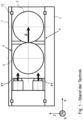
- Fig.1 shows a previously known roller press in which the loose roller is mounted in a sliding bearing at the top and bottom of the frame 1.
- a translational displacement of the loose roller against the fixed roller in particular by applying force to at least two force introduction points, also leads to reaction forces in the fixed bearings 12.
- the force is applied at two points (above and below the center of gravity of the floating roller), in particular by means of cylinders, in particular in a horizontal direction corresponding to the translational displacement direction (or in the direction in which the translational sliding bearing extends).
- This type of force application is due in particular to a force distribution in the frame that is as symmetrical as possible.
- the contact point of the rollers in the grinding gap is therefore also located at least approximately in the middle of the frame, at least with respect to the z-direction or with respect to the two force application points shown (force vector arrows F1, corresponding to the force exerted on the floating roller).
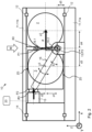
- Fig.2 shows a first variant for forming a one-sided lever arrangement 16 according to the present inventive concept.
- the force is applied at point P2 essentially in the horizontal direction (in particular only at a single force application point), with the load arm being approximately half as long as the force arm (d1 approximately equal to d2).
- the idler roller is pivoted by the force application.
- the pivot axis P3 (pivot point for the pivoting movement) is arranged at least approximately in the grinding gap X0 (d3 approximately equal to d4), i.e. at the same x-coordinate.
- the force can be applied either at just one point or at several points. In other words: In contrast to the structure according to Fig.1 A symmetrical arrangement of two force application cylinders is not required.
- Fig.2 the effective lever length is also indicated (dashed line), in projection orthogonal to the force application, namely on the one hand the force arm 16.1 (relatively narrower for illustration purposes), the length of which is defined by the position of the force application point P2, and on the other hand the load arm 16.2 (relatively wider for illustration purposes), the length of which is defined by the force transmission point P1 or by the contact point of the rollers in the grinding gap.
- the swivel movement is illustrated by the back and forth arrow around the swivel axis P3, 13. Depending on the load condition and the size or particle spectrum of the feed material, a swivel movement during operation can be more or less strong.
- the idler roller 3 is therefore held in the frame between the points P2 and P3.
- a force is transmitted between the idler roller and the frame only at these points, and indirectly also via the contact point P1.
- the at least one force application unit 15 can also be set up to actuate in both directions of action (opposite pivoting directions) (in particular both tensile and compressive forces).
- both directions of action opposite pivoting directions
- the floating roller can advantageously be pivoted back (purely) by gravity. This also promotes fast, reactive and thus low-stress operating behavior even with comparatively massive, heavy rollers.
- the type of force application in the grinding gap can also be adapted or optimized in a comparatively simple manner, in particular depending on the feed material. In other words: In contrast to the Fig.1 shown translational bearing, no great force is required to return the idler roller from the grinding gap (in Fig.1 to the left). This can also Provide advantages in terms of frame design and/or drive/actuator selection.
- a force triangle defined by the points P1, P2 and P3 can also be described.
- the respective roller axis is less important in this context.
- the load at point P3 also increases, i.e. the load acting on the swivel axis (especially large leverage when the rollers come into contact).
- a ratio P2/P3 to P1/P3 of at least approximately 1 to 2 can be preferred, especially if the number of cylinders (force application actuators) should be as small as possible (in relation to a translational bearing: in particular should be halved). In many cases, cost aspects are also of great importance, so the ratio of the distances will also be optimized in terms of costs. If the construction costs for the bearing point P3 increase more than the costs for the cylinders, the ratio will be smaller and vice versa. In this respect, the ratio can also be selected in individual cases in a range of, for example, 1 to 1 to 1 to 3, in particular 1 to 1.5 to 1 to 2.5, preferably 1 to 2.
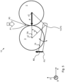
- Fig.3 shows a second variant for forming a one-sided lever arrangement 16 according to the present inventive concept.
- the force is applied at point P2 essentially in the vertical direction or essentially orthogonal to the reaction force F in the roller contact point (in particular also at least approximately orthogonal to an extension plane of the lower frame part or a foundation), with the load arm 16.2 being significantly shorter than half of the force arm 16.1 (z-distance P1 to P3 ⁇ x-distance P2 to P3).
- the pivot axis P3 is arranged in the grinding gap X0 (distance d3 approximately equal to distance d4).
- the idler roller can be mounted in a particularly reactive manner with regard to a return movement, and the swivel axis can be relieved of at least a certain amount of the weight of the idler roller.
- a frame section on the outside of the loose roller can be designed to be comparatively weak or can be omitted completely.
- a force transfer from the loose roller to the frame can also be carried out in particular by means of a diagonally connecting support or similar cross member between the loose roller and the frame, in particular by means of a frame support 11.1 or strut, in particular with a direction specification for the flow of force.
- Such a cross support is advantageously connected directly or indirectly to the underside of the frame or also directly to a foundation.
- the force transfer from the loose roller to the frame can be redirected in this way, in particular with a predetermined direction into the foundation. Effect:
- the force can be transferred in a very low-stress manner and the frame can be designed to be slim accordingly.
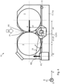
- Fig.4 shows a third variant for forming a one-sided lever arrangement 16 according to the present inventive concept.
- the Fig.4 illustrates several aspects which can each be advantageous in themselves, but which do not necessarily have to be implemented in combination with one another, in particular the following aspects: advantageously slim structure; advantageous force flow path; advantageous force coupling with a/the foundation (not shown; below frame part 11a); synergistic support of the rollers, in particular advantageous use of the pivot axis 13 as a common bearing axis (in particular for the purpose of compensating reaction forces).
- the force is applied at point P2 essentially in a vertical direction or at least approximately orthogonal to the reaction force at the roller contact point, with the load arm 16.2 being approximately half as long as the force arm (d1 approximately equal to d2).
- the pivot axis P3 is arranged in the grinding gap X0 (d3 approximately equal to d4), i.e. in the same x-position below the roller contact point.
- the fixed roller can optionally be mounted around the same pivot axis P3 or on the same pivot axis P3 as the loose roller and is supported against reaction forces around the pivot axis on the counter bearing 14. Active relative positioning is preferably only carried out by the loose roller 3.
- the counter bearing 14 can, however, optionally also be a fixed bearing to which the fixed roller is coupled in a fixed position (for example, bearing block 14 screwed to the frame).
- a relative movement of the fixed roller is, as the term "fixed roller” also makes clear, not necessarily required, even when using the swivel axis as a bearing axis for the fixed roller. Rather, the Fig.4
- the design shown also has the optional structural advantage that the swivel axis of the loose roller can also be used to support the fixed roller, particularly with regard to force compensation in the x-direction.
- the frame 11 has only one frame part 11a arranged on the underside. This can advantageously be coupled directly to a foundation (not shown), which promotes an advantageous force transfer, particularly in the case of very massive, large roller devices. In particular, no weight force components or reaction forces caused by the grinding process are introduced laterally into a frame. Fig.4 It is particularly evident that a configuration of the frame 11 without an upper frame part provides further advantages, for example with regard to general accessibility and/or with regard to material supply M.
- Fig.5 describes, generally with reference to all previously described embodiments of the invention, a relative arrangement of the axes (pivot axis and roller axes) relative to one another according to a triangular arrangement (with the triangular geometry of a triangle standing on its tip), wherein the symmetrical arrangement of the roller axes y2, y3 in relation to the pivot axis 13 is indicated by a purely geometrically explanatory dashed line.
- An at least approximately isosceles triangle TR is defined by the respective axis y2, y3, 13 as a corner point, wherein the base angle ⁇ is advantageously as small as possible.
- the isosceles triangle arrangement TR arises in particular when the rollers are in direct contact (grinding gap at least approximately zero, or not present). If the rollers are spaced apart relative to one another, for example due to feedstock in the grinding gap, the base angle becomes correspondingly smaller.
- the base angle ⁇ of the triangular arrangement TR is still comparatively large, especially in the range of 45 °; in an arrangement according to Fig.2 or Fig.3 (Pivot axis in z-direction comparatively close to roller contact point P1) the base angle ⁇ is comparatively small, in particular in the range of only approx. 25 ° to 35 °.
- the pivot axis is advantageously arranged at a (z) distance of less than half the roller diameter from the roller axes.
- the base angle ⁇ can, for example, take on a value in the range of 20 to 50 degrees (or in individual cases even up to 60 degrees).
- triangular arrangement TR it has been shown that by means of such a triangular arrangement TR, numerous advantages of the invention can be generally ensured in the different embodiments, regardless of the specific application.
- the structural concept according to the invention can therefore advantageously also be implemented specifically by such triangular arrangements TR, in particular with the size of the base angle or with the relative arrangement of the pivot axis as a structural design parameter.
- the relative x-position and/or relative z-position of the pivot axis can also be individually adjusted, for example slightly offset relative to the axis of rotation of the loose roller and moved out of the grinding gap.
- the triangular arrangement TR is preferably an isosceles triangular arrangement.
- the triangular arrangement TR is not necessarily only an isosceles triangle arrangement; rather, it is within the scope of professional adaptation to optimize the two base angles at least within a narrow range of variation for the respective application.
- the one-sided lever (one-sided lever arrangement) 16 is indicated schematically by a dashed line which extends from the pivot axis 13 to a force application point P2.
- the respective effective lever length ( Fig.2 ) is to be measured in particular orthogonal to the direction of force.
- the illustration based on a dashed line was chosen by the applicant because the section in which the one-sided lever is formed can be individually defined depending on the specifically selectable position for the force application point, as can the length of the lever and the length ratio between the force arm and the load arm. Irrespective of this, the loose roller is arranged both in the area of the load arm and in the area of the force arm, or these areas overlap (one-sided lever arrangement without a free load arm, i.e. without a rocker).
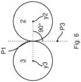
- Fig.6 shows, in a very simplified manner, only the fixed roller 2 and the loose roller 3 in relation to the pivot axis P3.
- a connecting line is drawn between the stationary roller axis y2 and the roller axis y3, which can be arranged at a variable location. At the roller contact point P1, this connecting line intersects the fixed roller 2 and the loose roller 3. The tangent of the fixed roller 2 and the loose roller 2 is perpendicular to this connecting line and runs through the pivot axis P3.
- Fig.7 a very extremely oversized grinding gap X0 is shown.
- the grinding gap X0 will be much smaller than the radius of the fixed roller 2 and the radius of the loose roller 3.
- the distance between the fixed roller 2 and the loose roller 3 now results in two spaced tangents.
- the pivot axis P3 is positioned exactly in the middle between the tangents.
Landscapes
- Engineering & Computer Science (AREA)
- Food Science & Technology (AREA)
- Crushing And Grinding (AREA)
- Rolls And Other Rotary Bodies (AREA)
- Grinding Of Cylindrical And Plane Surfaces (AREA)
- Crushing And Pulverization Processes (AREA)
- Rolling Contact Bearings (AREA)
- Press Drives And Press Lines (AREA)
- Finish Polishing, Edge Sharpening, And Grinding By Specific Grinding Devices (AREA)
Claims (14)
- Dispositif de presse à rouleaux (10) conçu pour broyer la matière première (M), en particulier sous la forme d'un broyeur à rouleaux, avec :- un rouleau fixe stationnaire (2) avec un axe de rouleau au moins approximativement stationnaire (y2) ;- un rouleau libre (3) avec un axe de rouleau (y3) qui peut être disposé dans une position variable par rapport au rouleau fixe ;- un cadre (11) supportant au moins le rouleau fixe et éventuellement le rouleau libre ;- au moins une unité d'application de force (15) agissant sur le rouleau libre en un point d'application de force (P2) ;dans lequel le rouleau fixe et le rouleau libre peuvent être montés et positionnés l'un par rapport à l'autre, en particulier au moyen de l'unité d'application de la force, pour l'application d'une force de broyage (F) et pour un contact mutuel dans un point de contact du rouleau (P1) ou pour définir un espace de broyage (x0) pour le matériau d'alimentation, dans lequel le rouleau libre (3) est monté avec l'axe de rouleau variable (y3) de manière à pouvoir pivoter autour d'un axe de pivotement (P3) à la manière d'un levier unilatéral (16), de sorte que la position relative du rouleau libre par rapport au rouleau fixe peut être définie par ce mouvement de pivotement, le levier unilatéral (16) étant formé entre l'axe de pivotement (P3) et le point d'application de la force (P2) ;caractérisé en ce que l'axe de pivotement (P3) est disposé sur la tangente du rouleau fixe (2) et du rouleau libre (3) au point de contact du rouleau (P1) ou, dans le cas d'une fente de rectification (x0) différente de zéro, l'axe de pivotement (P3) est disposé entre la tangente du rouleau fixe (2) et l'intersection de la ligne de raccordement entre l'axe du rouleau fixe (y2) et l'axe du rouleau (y3), qui peut être disposé dans une position variable, et la tangente du rouleau libre (3) à l'intersection de la ligne de jonction entre l'axe du rouleau fixe (y2) et l'axe du rouleau (y3), qui peut être disposé dans une position variable.
- Dispositif de presse à rouleaux selon la revendication précédente, caractérisé en ce que la distance entre l'axe de pivotement (P3) et la ligne de liaison entre l'axe du rouleau fixe (y2) et l'axe du rouleau (y3) qui peut être disposé dans une position variable le long d'une ligne droite perpendiculaire à la ligne de liaison entre l'axe du rouleau fixe (y2) et l'axe du rouleau (y3) qui peut être disposé dans une position variable et à travers l'axe de pivotement (P3) est d'au moins 0,15 fois la somme du rayon du rouleau fixe (2) et du rayon du rouleau libre (3) et au maximum 1 fois la somme du rayon du rouleau fixe (2) et du rayon du rouleau libre (3).
- Dispositif de presse à rouleaux selon l'une des revendications précédentes, caractérisé en ce que la distance entre l'axe de pivotement (P3) et le point d'application de la force (P2) est de 1 à 5 fois la distance entre l'axe de pivotement (P3) et la ligne de jonction entre l'axe du rouleau monté fixe (y2) et l'axe du rouleau (y3) qui peut être disposé dans une position variable le long d'une ligne perpendiculaire à la ligne de jonction entre l'axe du rouleau monté fixe (y2) et l'axe du rouleau (y3) qui peut être disposé dans une position variable. (y3) le long d'une ligne droite perpendiculaire à la ligne de jonction entre l'axe du rouleau monté de manière fixe (y2) et l'axe du rouleau (y3), qui peut être disposé dans une position variable, et à travers l'axe de pivotement (P3).
- Dispositif de presse à rouleaux selon l'une des revendications précédentes, caractérisé en ce que le levier unilatéral (16) comprend la ligne de liaison rectiligne entre le point d'application de la force (P2) et l'axe de pivotement (P3).
- Dispositif de presse à rouleaux selon la revendication 4caractérisé par le fait que l'axe du rouleau (y3), qui peut être disposé dans une position variable, traverse le levier unilatéral (16).
- Dispositif de presse à rouleaux selon l'une des revendications 4 à 5caractérisé par le fait que l'axe du rouleau (y3), qui peut être disposé dans une position variable, est éloigné de la ligne droite de liaison entre le point d'application de la force (P2) et l'axe de pivotement (P3) d'un maximum de 0,1 fois la longueur de la ligne droite de liaison entre le point d'application de la force (P2) et l'axe de pivotement (P3).
- Dispositif de presse à rouleaux selon l'une des revendications précédentes, caractérisé en ce que la force est appliquée au point d'application de la force (P2) à un angle de 75 ° à 105 ° par rapport à la ligne de jonction entre l'axe du rouleau monté de manière fixe (y2) et l'axe du rouleau (y3) qui peut être disposé dans une position variable.
- Dispositif de presse à rouleaux selon l'une des revendications précédentes, caractérisé en ce que le point de contact du rouleau (P1) est disposé dans une section entre le point d'application de la force (P2) et l'axe de pivotement (P3) et/ou est disposé à une distance de l'axe de pivotement inférieure à la longueur du levier unilatéral, et en ce que le point de contact du rouleau (P1) définit un/le bras de charge (16.2) du levier unilatéral.
- Dispositif de presse à rouleaux selon l'une des revendications précédentes, caractérisé en ce que les axes des rouleaux, lorsque les rouleaux sont en contact au point de contact des rouleaux, sont disposés par rapport à l'axe de pivotement de telle sorte qu'une ligne de jonction passant par ces trois axes dans un plan (vue de côté) s'étendant orthogonalement à ceux-ci forme un triangle ou une disposition triangulaire, de préférence avec les angles de base à la ligne de jonction entre les axes des rouleaux dans chaque cas inférieurs à 50 degrés, en particulier inférieurs à 45 degrés, de préférence inférieurs à 40 degrés, en outre de préférence inférieurs à 35 degrés.
- Dispositif de presse à rouleaux selon l'une des revendications précédentes, caractérisé par le fait que le rouleau libre est monté pivotant et disposé de telle sorte que la force gravitationnelle agissant au centre de gravité du rouleau libre agit sur un/sur le bras de charge du levier unilatéral de manière à augmenter la fente de broyage dans le sens d'un mouvement de rappel.
- Dispositif de presse à rouleaux selon l'une des revendications précédentes, caractérisé en ce que l'application de la force autour de l'axe de pivotement (P3) est effectuée au moyen d'au moins un plongeur, en particulier au moyen d'un plongeur avec dispositif de basculement, en particulier au moyen d'un plongeur avec hydrostat comme dispositif de basculement.
- Procédé de broyage d'une matière première (M) au moyen d'un dispositif de pressage à rouleaux (10) selon l'une des revendications précédentes, comprenant les étapes suivantes : - entraînement d'au moins un rouleau fixe (2) monté de manière fixe avec un axe de rouleau (y2) monté de manière au moins approximativement fixe et d'un rouleau libre (3) avec un axe de rouleau (y2)
pouvant être disposé
dans une position variable ;- application d'une force au rouleau libre (3) pour appliquer une force de broyage (F) et pour positionner le rouleau libre par rapport au rouleau fixe (2) ;caractérisé en ce que le rouleau libre avec l'axe de rouleau à position variable est pivoté autour d'un axe de pivot (P3) par l'application d'une force à la manière d'un levier unilatéral (16) et la position relative du rouleau libre par rapport au rouleau fixe est ainsi définie, l'application de la force a lieu à un point d'application de la force (P2) du levier unilatéral, en particulier à un point d'application de la force qui est au moins aussi éloigné, de préférence plus éloigné, de l'axe du rouleau à position variable (y3) en ce qui concerne l'effet de levier que l'axe du rouleau à position variable n'est éloigné de l'axe de pivotement (P3). - Méthode selon la revendication 12caractérisé par le fait que la force est appliquée au bras de force du levier unilatéral, le rouleau libre (3) étant pivoté par rapport au rouleau fixe (2) de manière à ce que le rouleau libre entre en contact avec le rouleau fixe dans la section du bras de force et définisse le bras de charge par le point de contact du rouleau (P1) ou par le matériau d'alimentation contacté (M).
- Méthode selon l'une des revendications 12 à 13caractérisé par le fait que le rouleau libre (3) est positionné par rapport au rouleau fixe (2) exclusivement par le mouvement de pivotement, c'est-à-dire sans déplacement en translation ; et/ou dans lequel le mouvement de pivotement est initié exclusivement par une action ou une application de force dans la direction de la translation, c'est-à-dire sans couple ou sans mouvement de positionnement rotatif.
Applications Claiming Priority (7)
| Application Number | Priority Date | Filing Date | Title |
|---|---|---|---|
| DE102020200404.8A DE102020200404A1 (de) | 2020-01-14 | 2020-01-14 | Vorrichtung und Verfahren zum Mahlen von Einsatzmaterial sowie Steuerungs-/Regelungseinrichtung und Verwendung |
| BE20205020A BE1027983B1 (de) | 2020-01-14 | 2020-01-14 | Vorrichtung und Verfahren zum Mahlen von Einsatzmaterial sowie Steuerungs-/Regelungseinrichtung und Verwendung |
| BE20205023A BE1027987B1 (de) | 2020-01-14 | 2020-01-14 | Vorrichtung und Verfahren zum Mahlen von Einsatzmaterial sowie Steuerungs-/Regelungseinrichtung und Verwendung |
| DE102020200402.1A DE102020200402A1 (de) | 2020-01-14 | 2020-01-14 | Vorrichtung und Verfahren zum Mahlen von Einsatzmaterial sowie Steuerungs-/Regelungseinrichtung und Verwendung |
| BE20205022A BE1027984B1 (de) | 2020-01-14 | 2020-01-14 | Vorrichtung und Verfahren zum Mahlen von Einsatzmaterial sowie Steuerungs-/Regelungseinrichtung und Verwendung |
| DE102020200401.3A DE102020200401A1 (de) | 2020-01-14 | 2020-01-14 | Vorrichtung und Verfahren zum Mahlen von Einsatzmaterial sowie Steuerungs-/Regelungseinrichtung und Verwendung |
| PCT/EP2021/050209 WO2021144191A1 (fr) | 2020-01-14 | 2021-01-08 | Dispositif et procédé de broyage de matériau d'entrée |
Publications (3)
| Publication Number | Publication Date |
|---|---|
| EP4090468A1 EP4090468A1 (fr) | 2022-11-23 |
| EP4090468C0 EP4090468C0 (fr) | 2024-04-10 |
| EP4090468B1 true EP4090468B1 (fr) | 2024-04-10 |
Family
ID=74181199
Family Applications (1)
| Application Number | Title | Priority Date | Filing Date |
|---|---|---|---|
| EP21700191.6A Active EP4090468B1 (fr) | 2020-01-14 | 2021-01-08 | Dispositif et procédé pour broyer une matière de charge |
Country Status (8)
| Country | Link |
|---|---|
| US (1) | US12179212B2 (fr) |
| EP (1) | EP4090468B1 (fr) |
| CN (1) | CN115315315B (fr) |
| AU (1) | AU2021208299B9 (fr) |
| CL (1) | CL2022001589A1 (fr) |
| PE (1) | PE20221431A1 (fr) |
| WO (1) | WO2021144191A1 (fr) |
| ZA (1) | ZA202207812B (fr) |
Citations (1)
| Publication number | Priority date | Publication date | Assignee | Title |
|---|---|---|---|---|
| DE3724742A1 (de) * | 1987-07-25 | 1989-02-02 | Westfaelische Maschbau Gmbh | Walzenbrecher mit festwalze und loswalze |
Family Cites Families (12)
| Publication number | Priority date | Publication date | Assignee | Title |
|---|---|---|---|---|
| DE2540269B2 (de) * | 1975-09-10 | 1980-12-18 | Kloeckner-Humboldt-Deutz Ag, 5000 Koeln | Einstellbare Stützvorrichtung für die Loswalze einer Walzenmühle |
| GB2103107A (en) | 1980-12-04 | 1983-02-16 | Robinson And Son Plc Thomas | Mounting arrangement for a grinding roll |
| IT1147385B (it) | 1981-07-16 | 1986-11-19 | Giacomo Ferrero | Cilindraia o mulino a cilindri a regolazione e sicurezza idrauliche |
| GB2116877B (en) * | 1982-03-20 | 1985-09-11 | Simon Ltd Henry | A rollermill |
| DE3818540A1 (de) * | 1988-05-31 | 1989-12-07 | Rieter Werke Haendle | Walzwerk mit verstellbarem walzenspalt fuer keramische massen |
| CN2296764Y (zh) * | 1997-05-01 | 1998-11-11 | 杨宏琰 | 摇臂型辊式原料制备设备 |
| US6685118B1 (en) * | 2000-12-19 | 2004-02-03 | Robert M. Williams, Jr. | Two roll crusher and method of roller adjustment |
| DE102013010220A1 (de) | 2013-06-18 | 2014-12-18 | Khd Humboldt Wedag Gmbh | Hochdruck-Walzenpresse mit Pendelaufhängung |
| DE102015110033A1 (de) | 2015-06-23 | 2016-12-29 | Gebr. Pfeiffer Se | Gutbett-Walzenmühle |
| CN108187802B (zh) * | 2015-08-10 | 2020-08-11 | 福建美斯拓机械设备有限公司 | 一种松紧可调的对辊式粉碎制砂机 |
| DE102015114998B4 (de) * | 2015-09-07 | 2019-05-09 | Mbe Coal & Minerals Technology Gmbh | Rollenpresse |
| DE102015114992B4 (de) | 2015-09-07 | 2017-07-20 | Mbe Coal & Minerals Technology Gmbh | Rollenpresse |
-
2021
- 2021-01-08 CN CN202180009091.3A patent/CN115315315B/zh active Active
- 2021-01-08 PE PE2022001090A patent/PE20221431A1/es unknown
- 2021-01-08 US US17/792,678 patent/US12179212B2/en active Active
- 2021-01-08 WO PCT/EP2021/050209 patent/WO2021144191A1/fr not_active Ceased
- 2021-01-08 AU AU2021208299A patent/AU2021208299B9/en active Active
- 2021-01-08 EP EP21700191.6A patent/EP4090468B1/fr active Active
-
2022
- 2022-06-14 CL CL2022001589A patent/CL2022001589A1/es unknown
- 2022-07-13 ZA ZA2022/07812A patent/ZA202207812B/en unknown
Patent Citations (1)
| Publication number | Priority date | Publication date | Assignee | Title |
|---|---|---|---|---|
| DE3724742A1 (de) * | 1987-07-25 | 1989-02-02 | Westfaelische Maschbau Gmbh | Walzenbrecher mit festwalze und loswalze |
Also Published As
| Publication number | Publication date |
|---|---|
| US20230042116A1 (en) | 2023-02-09 |
| AU2021208299A1 (en) | 2022-08-18 |
| BR112022011712A2 (pt) | 2022-09-06 |
| CN115315315A (zh) | 2022-11-08 |
| WO2021144191A1 (fr) | 2021-07-22 |
| US12179212B2 (en) | 2024-12-31 |
| EP4090468C0 (fr) | 2024-04-10 |
| PE20221431A1 (es) | 2022-09-21 |
| EP4090468A1 (fr) | 2022-11-23 |
| CN115315315B (zh) | 2025-03-11 |
| ZA202207812B (en) | 2024-12-18 |
| AU2021208299B2 (en) | 2023-07-20 |
| CL2022001589A1 (es) | 2023-01-20 |
| AU2021208299B9 (en) | 2023-07-27 |
| CA3163282A1 (fr) | 2021-07-22 |
Similar Documents
| Publication | Publication Date | Title |
|---|---|---|
| EP3313576B1 (fr) | Broyeur à rouleaux à lit de matériau | |
| EP2509725B1 (fr) | Presse radiale | |
| EP3597300B1 (fr) | Paquet de rouleaux pour dispositifs de broyage, dispositifs de broyage et procédé | |
| EP4294572B1 (fr) | Presse à rouleaux haute pression | |
| DE102008039542B4 (de) | Rollenmühle | |
| EP2125228B1 (fr) | Broyeur à rouleaux | |
| WO2008068125A1 (fr) | Broyeur à galets | |
| WO2014202288A1 (fr) | Presse à rouleaux haute pression à suspension pendulaire | |
| EP2888051B1 (fr) | Dispositif de broyage | |
| EP4106924B1 (fr) | Presse à cylindres haute pression | |
| BE1027987B1 (de) | Vorrichtung und Verfahren zum Mahlen von Einsatzmaterial sowie Steuerungs-/Regelungseinrichtung und Verwendung | |
| DE102020200401A1 (de) | Vorrichtung und Verfahren zum Mahlen von Einsatzmaterial sowie Steuerungs-/Regelungseinrichtung und Verwendung | |
| BE1027984B1 (de) | Vorrichtung und Verfahren zum Mahlen von Einsatzmaterial sowie Steuerungs-/Regelungseinrichtung und Verwendung | |
| BE1027983B1 (de) | Vorrichtung und Verfahren zum Mahlen von Einsatzmaterial sowie Steuerungs-/Regelungseinrichtung und Verwendung | |
| AT507110B1 (de) | Presse zum umformen von material | |
| EP4090468A1 (fr) | Dispositif et procédé de broyage de matériau d'entrée | |
| DE102020200402A1 (de) | Vorrichtung und Verfahren zum Mahlen von Einsatzmaterial sowie Steuerungs-/Regelungseinrichtung und Verwendung | |
| DE102020200404A1 (de) | Vorrichtung und Verfahren zum Mahlen von Einsatzmaterial sowie Steuerungs-/Regelungseinrichtung und Verwendung | |
| EP3860763B1 (fr) | Dispositif d'alimentation avec un élément de dosage pour une presse à rouleaux | |
| DE202021103408U1 (de) | Hochdruck-Walzenpresse | |
| EP4003677B1 (fr) | Entraînement oscillant de machine | |
| DE10218780B4 (de) | Walzenmühle zur Zerkleinerung von grobkörnigem Material | |
| WO2026092823A1 (fr) | Broyeur à rouleaux et son procédé de fonctionnement | |
| DE20212079U1 (de) | Brecher | |
| DE1807948A1 (de) | Vorrichtung zur Verringerung der Dicke von Metall |
Legal Events
| Date | Code | Title | Description |
|---|---|---|---|
| STAA | Information on the status of an ep patent application or granted ep patent |
Free format text: STATUS: UNKNOWN |
|
| STAA | Information on the status of an ep patent application or granted ep patent |
Free format text: STATUS: THE INTERNATIONAL PUBLICATION HAS BEEN MADE |
|
| PUAI | Public reference made under article 153(3) epc to a published international application that has entered the european phase |
Free format text: ORIGINAL CODE: 0009012 |
|
| STAA | Information on the status of an ep patent application or granted ep patent |
Free format text: STATUS: REQUEST FOR EXAMINATION WAS MADE |
|
| 17P | Request for examination filed |
Effective date: 20220816 |
|
| AK | Designated contracting states |
Kind code of ref document: A1 Designated state(s): AL AT BE BG CH CY CZ DE DK EE ES FI FR GB GR HR HU IE IS IT LI LT LU LV MC MK MT NL NO PL PT RO RS SE SI SK SM TR |
|
| DAV | Request for validation of the european patent (deleted) | ||
| DAX | Request for extension of the european patent (deleted) | ||
| RAP1 | Party data changed (applicant data changed or rights of an application transferred) |
Owner name: THYSSENKRUPP AG Owner name: THYSSENKRUPP POLYSIUS GMBH |
|
| GRAP | Despatch of communication of intention to grant a patent |
Free format text: ORIGINAL CODE: EPIDOSNIGR1 |
|
| STAA | Information on the status of an ep patent application or granted ep patent |
Free format text: STATUS: GRANT OF PATENT IS INTENDED |
|
| INTG | Intention to grant announced |
Effective date: 20231103 |
|
| GRAS | Grant fee paid |
Free format text: ORIGINAL CODE: EPIDOSNIGR3 |
|
| GRAA | (expected) grant |
Free format text: ORIGINAL CODE: 0009210 |
|
| STAA | Information on the status of an ep patent application or granted ep patent |
Free format text: STATUS: THE PATENT HAS BEEN GRANTED |
|
| AK | Designated contracting states |
Kind code of ref document: B1 Designated state(s): AL AT BE BG CH CY CZ DE DK EE ES FI FR GB GR HR HU IE IS IT LI LT LU LV MC MK MT NL NO PL PT RO RS SE SI SK SM TR |
|
| REG | Reference to a national code |
Ref country code: GB Ref legal event code: FG4D Free format text: NOT ENGLISH |
|
| REG | Reference to a national code |
Ref country code: CH Ref legal event code: EP |
|
| REG | Reference to a national code |
Ref country code: DE Ref legal event code: R096 Ref document number: 502021003291 Country of ref document: DE |
|
| REG | Reference to a national code |
Ref country code: IE Ref legal event code: FG4D Free format text: LANGUAGE OF EP DOCUMENT: GERMAN |
|
| U01 | Request for unitary effect filed |
Effective date: 20240508 |
|
| U07 | Unitary effect registered |
Designated state(s): AT BE BG DE DK EE FI FR IT LT LU LV MT NL PT SE SI Effective date: 20240517 |
|
| PG25 | Lapsed in a contracting state [announced via postgrant information from national office to epo] |
Ref country code: IS Free format text: LAPSE BECAUSE OF FAILURE TO SUBMIT A TRANSLATION OF THE DESCRIPTION OR TO PAY THE FEE WITHIN THE PRESCRIBED TIME-LIMIT Effective date: 20240810 |
|
| PG25 | Lapsed in a contracting state [announced via postgrant information from national office to epo] |
Ref country code: HR Free format text: LAPSE BECAUSE OF FAILURE TO SUBMIT A TRANSLATION OF THE DESCRIPTION OR TO PAY THE FEE WITHIN THE PRESCRIBED TIME-LIMIT Effective date: 20240410 |
|
| PG25 | Lapsed in a contracting state [announced via postgrant information from national office to epo] |
Ref country code: GR Free format text: LAPSE BECAUSE OF FAILURE TO SUBMIT A TRANSLATION OF THE DESCRIPTION OR TO PAY THE FEE WITHIN THE PRESCRIBED TIME-LIMIT Effective date: 20240711 |
|
| PG25 | Lapsed in a contracting state [announced via postgrant information from national office to epo] |
Ref country code: ES Free format text: LAPSE BECAUSE OF FAILURE TO SUBMIT A TRANSLATION OF THE DESCRIPTION OR TO PAY THE FEE WITHIN THE PRESCRIBED TIME-LIMIT Effective date: 20240410 |
|
| PG25 | Lapsed in a contracting state [announced via postgrant information from national office to epo] |
Ref country code: PL Free format text: LAPSE BECAUSE OF FAILURE TO SUBMIT A TRANSLATION OF THE DESCRIPTION OR TO PAY THE FEE WITHIN THE PRESCRIBED TIME-LIMIT Effective date: 20240410 |
|
| PG25 | Lapsed in a contracting state [announced via postgrant information from national office to epo] |
Ref country code: PL Free format text: LAPSE BECAUSE OF FAILURE TO SUBMIT A TRANSLATION OF THE DESCRIPTION OR TO PAY THE FEE WITHIN THE PRESCRIBED TIME-LIMIT Effective date: 20240410 Ref country code: NO Free format text: LAPSE BECAUSE OF FAILURE TO SUBMIT A TRANSLATION OF THE DESCRIPTION OR TO PAY THE FEE WITHIN THE PRESCRIBED TIME-LIMIT Effective date: 20240710 Ref country code: IS Free format text: LAPSE BECAUSE OF FAILURE TO SUBMIT A TRANSLATION OF THE DESCRIPTION OR TO PAY THE FEE WITHIN THE PRESCRIBED TIME-LIMIT Effective date: 20240810 Ref country code: HR Free format text: LAPSE BECAUSE OF FAILURE TO SUBMIT A TRANSLATION OF THE DESCRIPTION OR TO PAY THE FEE WITHIN THE PRESCRIBED TIME-LIMIT Effective date: 20240410 Ref country code: GR Free format text: LAPSE BECAUSE OF FAILURE TO SUBMIT A TRANSLATION OF THE DESCRIPTION OR TO PAY THE FEE WITHIN THE PRESCRIBED TIME-LIMIT Effective date: 20240711 Ref country code: ES Free format text: LAPSE BECAUSE OF FAILURE TO SUBMIT A TRANSLATION OF THE DESCRIPTION OR TO PAY THE FEE WITHIN THE PRESCRIBED TIME-LIMIT Effective date: 20240410 Ref country code: RS Free format text: LAPSE BECAUSE OF FAILURE TO SUBMIT A TRANSLATION OF THE DESCRIPTION OR TO PAY THE FEE WITHIN THE PRESCRIBED TIME-LIMIT Effective date: 20240710 |
|
| REG | Reference to a national code |
Ref country code: DE Ref legal event code: R097 Ref document number: 502021003291 Country of ref document: DE |
|
| PG25 | Lapsed in a contracting state [announced via postgrant information from national office to epo] |
Ref country code: CZ Free format text: LAPSE BECAUSE OF FAILURE TO SUBMIT A TRANSLATION OF THE DESCRIPTION OR TO PAY THE FEE WITHIN THE PRESCRIBED TIME-LIMIT Effective date: 20240410 |
|
| PG25 | Lapsed in a contracting state [announced via postgrant information from national office to epo] |
Ref country code: SK Free format text: LAPSE BECAUSE OF FAILURE TO SUBMIT A TRANSLATION OF THE DESCRIPTION OR TO PAY THE FEE WITHIN THE PRESCRIBED TIME-LIMIT Effective date: 20240410 Ref country code: RO Free format text: LAPSE BECAUSE OF FAILURE TO SUBMIT A TRANSLATION OF THE DESCRIPTION OR TO PAY THE FEE WITHIN THE PRESCRIBED TIME-LIMIT Effective date: 20240410 |
|
| PG25 | Lapsed in a contracting state [announced via postgrant information from national office to epo] |
Ref country code: SM Free format text: LAPSE BECAUSE OF FAILURE TO SUBMIT A TRANSLATION OF THE DESCRIPTION OR TO PAY THE FEE WITHIN THE PRESCRIBED TIME-LIMIT Effective date: 20240410 |
|
| PG25 | Lapsed in a contracting state [announced via postgrant information from national office to epo] |
Ref country code: SM Free format text: LAPSE BECAUSE OF FAILURE TO SUBMIT A TRANSLATION OF THE DESCRIPTION OR TO PAY THE FEE WITHIN THE PRESCRIBED TIME-LIMIT Effective date: 20240410 Ref country code: SK Free format text: LAPSE BECAUSE OF FAILURE TO SUBMIT A TRANSLATION OF THE DESCRIPTION OR TO PAY THE FEE WITHIN THE PRESCRIBED TIME-LIMIT Effective date: 20240410 Ref country code: RO Free format text: LAPSE BECAUSE OF FAILURE TO SUBMIT A TRANSLATION OF THE DESCRIPTION OR TO PAY THE FEE WITHIN THE PRESCRIBED TIME-LIMIT Effective date: 20240410 Ref country code: CZ Free format text: LAPSE BECAUSE OF FAILURE TO SUBMIT A TRANSLATION OF THE DESCRIPTION OR TO PAY THE FEE WITHIN THE PRESCRIBED TIME-LIMIT Effective date: 20240410 |
|
| PLBE | No opposition filed within time limit |
Free format text: ORIGINAL CODE: 0009261 |
|
| STAA | Information on the status of an ep patent application or granted ep patent |
Free format text: STATUS: NO OPPOSITION FILED WITHIN TIME LIMIT |
|
| U20 | Renewal fee for the european patent with unitary effect paid |
Year of fee payment: 5 Effective date: 20250128 |
|
| 26N | No opposition filed |
Effective date: 20250113 |
|
| REG | Reference to a national code |
Ref country code: CH Ref legal event code: PL |
|
| PG25 | Lapsed in a contracting state [announced via postgrant information from national office to epo] |
Ref country code: MC Free format text: LAPSE BECAUSE OF FAILURE TO SUBMIT A TRANSLATION OF THE DESCRIPTION OR TO PAY THE FEE WITHIN THE PRESCRIBED TIME-LIMIT Effective date: 20240410 |
|
| GBPC | Gb: european patent ceased through non-payment of renewal fee |
Effective date: 20250108 |
|
| PG25 | Lapsed in a contracting state [announced via postgrant information from national office to epo] |
Ref country code: GB Free format text: LAPSE BECAUSE OF NON-PAYMENT OF DUE FEES Effective date: 20250108 |
|
| PG25 | Lapsed in a contracting state [announced via postgrant information from national office to epo] |
Ref country code: CH Free format text: LAPSE BECAUSE OF NON-PAYMENT OF DUE FEES Effective date: 20250131 |
|
| PG25 | Lapsed in a contracting state [announced via postgrant information from national office to epo] |
Ref country code: IE Free format text: LAPSE BECAUSE OF NON-PAYMENT OF DUE FEES Effective date: 20250108 |
|
| U20 | Renewal fee for the european patent with unitary effect paid |
Year of fee payment: 6 Effective date: 20260129 |
|
| PGFP | Annual fee paid to national office [announced via postgrant information from national office to epo] |
Ref country code: TR Payment date: 20260106 Year of fee payment: 6 |
|
| PG25 | Lapsed in a contracting state [announced via postgrant information from national office to epo] |
Ref country code: CY Free format text: LAPSE BECAUSE OF FAILURE TO SUBMIT A TRANSLATION OF THE DESCRIPTION OR TO PAY THE FEE WITHIN THE PRESCRIBED TIME-LIMIT Effective date: 20240410 |
|
| U1N | Appointed representative for the unitary patent procedure changed after the registration of the unitary effect |
Representative=s name: MOSER GOETZE & PARTNER PATENTANWAELTE MBB; DE |