EP4090480B1 - Agrafeuse pour métal - Google Patents
Agrafeuse pour métal Download PDFInfo
- Publication number
- EP4090480B1 EP4090480B1 EP21700736.8A EP21700736A EP4090480B1 EP 4090480 B1 EP4090480 B1 EP 4090480B1 EP 21700736 A EP21700736 A EP 21700736A EP 4090480 B1 EP4090480 B1 EP 4090480B1
- Authority
- EP
- European Patent Office
- Prior art keywords
- punching
- punching tool
- tool
- mpa
- lie
- Prior art date
- Legal status (The legal status is an assumption and is not a legal conclusion. Google has not performed a legal analysis and makes no representation as to the accuracy of the status listed.)
- Active
Links
Images

Classifications
-
- B—PERFORMING OPERATIONS; TRANSPORTING
- B21—MECHANICAL METAL-WORKING WITHOUT ESSENTIALLY REMOVING MATERIAL; PUNCHING METAL
- B21C—MANUFACTURE OF METAL SHEETS, WIRE, RODS, TUBES, PROFILES OR LIKE SEMI-MANUFACTURED PRODUCTS OTHERWISE THAN BY ROLLING; AUXILIARY OPERATIONS USED IN CONNECTION WITH METAL-WORKING WITHOUT ESSENTIALLY REMOVING MATERIAL
- B21C47/00—Winding-up, coiling or winding-off metal wire, metal band or other flexible metal material characterised by features relevant to metal processing only
- B21C47/24—Transferring coils to or from winding apparatus or to or from operative position therein; Preventing uncoiling during transfer
- B21C47/247—Joining wire or band ends
-
- B—PERFORMING OPERATIONS; TRANSPORTING
- B21—MECHANICAL METAL-WORKING WITHOUT ESSENTIALLY REMOVING MATERIAL; PUNCHING METAL
- B21D—WORKING OR PROCESSING OF SHEET METAL OR METAL TUBES, RODS OR PROFILES WITHOUT ESSENTIALLY REMOVING MATERIAL; PUNCHING METAL
- B21D39/00—Application of procedures in order to connect objects or parts, e.g. coating with sheet metal otherwise than by plating; Tube expanders
- B21D39/03—Application of procedures in order to connect objects or parts, e.g. coating with sheet metal otherwise than by plating; Tube expanders of sheet metal otherwise than by folding
- B21D39/034—Joining superposed plates by piercing
-
- B—PERFORMING OPERATIONS; TRANSPORTING
- B21—MECHANICAL METAL-WORKING WITHOUT ESSENTIALLY REMOVING MATERIAL; PUNCHING METAL
- B21D—WORKING OR PROCESSING OF SHEET METAL OR METAL TUBES, RODS OR PROFILES WITHOUT ESSENTIALLY REMOVING MATERIAL; PUNCHING METAL
- B21D39/00—Application of procedures in order to connect objects or parts, e.g. coating with sheet metal otherwise than by plating; Tube expanders
- B21D39/03—Application of procedures in order to connect objects or parts, e.g. coating with sheet metal otherwise than by plating; Tube expanders of sheet metal otherwise than by folding
Definitions
- the present invention relates to a stapling machine for connecting an end section of an outgoing metal strip to a start section of an incoming metal strip for a continuously operated strip system, as is typically used in metal strip treatment or metal strip finishing plants.
- the present invention relates to a strip system comprising the stapling machine according to the invention and a method for connecting an end section of an outgoing metal strip to a start section of an incoming metal strip in a continuously operated strip system.
- stitching machines are used to maintain the continuous belt movement and connect the new metal belt to the outgoing metal belt in the infeed area of the belt system.
- different types of connection can be used, such as clinching, gluing, welding or punching. Specialists are often familiar with corresponding stitching machines from the state of the art.
- punched connections also known as stitching.
- Such stapling machines have a single stapling tool built into the stapling machine in a single or double row design.
- stitching can generally be used for metal strips up to a thickness of 6 mm.
- the stapling tools have technologically unsuitable parameters, since they are typically designed for the minimum metal strip thicknesses to be stapled.
- the present invention is therefore based on the object of providing a stitching machine of the type described at the outset, which can be used for a larger range of thicknesses and/or strengths without having the disadvantages known from the prior art. Furthermore, the object of the present invention is to provide an improved method for connecting an end section of an outgoing metal strip to a start section of an incoming metal strip in a continuously operated strip system.
- the object is achieved by a stapling machine having the features of claim 1 and a method having the features of claim 6.
- a stitching machine for a continuously operated strip system for connecting the end section of an outgoing metal strip to the beginning section of an incoming metal strip, which has a first punching tool and a second punching tool.
- the first punching tool is designed to connect the metal strips to one another when their thicknesses are in a first thickness range and/or their strengths are in a first strength range.
- the second punching tool is designed to connect the metal strips to one another when their thicknesses are in a second thickness range and/or their strengths are in a second strength range, wherein both thickness ranges and/or strength ranges differ from one another.
- the first thickness range is 0.2 to 2.5 mm and the second thickness range is 2.0 to 3.5 mm.
- the first strength range is 20 MPa to 250 MPa for aluminum or an alloy thereof, and 100 MPa to 350 MPa for steel and the second strength range is 200 MPa to 600 MPa for aluminum or an alloy thereof, and 300 MPa to 1000 MPa for steel.
- metal strips with a first thickness range and/or a first strength range are connected to one another with a first punching tool and metal strips with a second thickness range and/or a second strength range are connected to one another with a second punching tool, wherein both thickness ranges and/or strength ranges differ from one another.
- the two different punching tools mean that the right punching tool can be selected and used to meet the connection requirements, depending on the thickness of the strip to be stapled and/or the strength of the metal strips to be joined. This not only has a positive effect on the quality of the cutting edges, but also protects the punching tool used.
- stitching is used as the type of connection.
- Stitching is a specific punching process in which a positive connection between the two metal strips is created by creating a punching geometry and subsequent stretching.
- the connection by means of stitching seams can advantageously be carried out in one row or, more preferably, in two rows.
- the metal strips to be joined together are aluminium strips or steel strips.
- the first punching tool has a first punching pattern and the second punching tool has a second punching pattern, whereby both punching patterns differ from one another.
- the punching patterns are different punching geometries that are punched into the corresponding metal strip, for example aluminum or steel, using the punch and the die. Due to the different punching patterns that the two punching tools have, the punching tools can be optimally designed for the respective metal strips, so that the stapling machine according to the invention can be used for a larger range of materials.
- the first punching tool has a first cutting gap and the second punching tool has a second cutting gap that differs from the first cutting gap.
- This also has a beneficial effect on the usability of the stapling machine, since the punching tools can thus be optimally designed specifically for the range of materials to be stapled.
- the stapling machine according to the invention is designed in such a way that the tool change between the first and the second punching tool is fully automatic. This makes it possible to carry out the tool change while the belt is running. It is therefore not necessary to stop the entire belt process line of the belt system.
- both punching tools are arranged in a punching tool cassette.
- the punching tool cassette can preferably be moved within the stapling machine using a displacement device.
- the stapling machine has, for example, a motor and a rack that interacts with the punching tool cassette and allows the tool to be changed quickly.
- the punching tool cassette is arranged in the stapling machine in such a way that one punching tool is arranged in a punching position and the other in a parking position.
- the punching tool in the punching position is exchanged for the other stored punching tool by the shifting device of the stapling machine shifting the punching tool cassette accordingly.
- the punching tool stored in the parking position is advantageously protected from damage by means of wear plates.
- the arrangement of the punching tools in a punching tool cassette thus enables improved and faster tool changes, so that the effort for the entire tool change process is reduced.
- the tool change preferably takes place while the belt is running between two stitch seams.
- the tool change can take place while the belt is at a standstill.
- each of the punching tools is designed with a blow-off by means of compressed air and/or a tool lubrication.
- a further aspect of the present invention also relates to a belt system comprising the stapling machine according to the invention.
- FIG. 1 a stitching machine 1 for connecting the end section of an outgoing metal strip with the beginning section of an incoming metal strip for a continuously operated strip system is shown, as typically used in metal strip treatment or metal strip finishing plants. In the present illustration, the metal strips are not shown, only the strip path B is indicated.
- the stapling machine 1 comprises a first punching tool 20, which is designed to connect metal strips whose thicknesses lie in a first thickness range, preferably in the range of 0.2 to 2.5 mm, to one another, and a second punching tool 30, which is designed to connect metal strips whose thicknesses lie in a second thickness range, preferably 2 to 3.5 mm, to one another, wherein both thickness ranges differ from one another.
- the two punching tools 20, 30 are arranged in a punching tool cassette 80, which can be moved within the stapling machine 1 by means of a displacement device 60, so that the first punching tool 20 can be arranged in a punching position 50 and the second punching tool 30 in a parking position 70 within the stapling machine 1.
- the stapling machine 1 has a motor (not shown) and a rack 10, which interacts with the punching tool cassette 80 and allows for rapid tool changes.
- each of the punching tools 20, 30 has a corresponding punch and a die (not shown).
- the punch and die of the first punching tool 20 differ from the second punching tool 30, ie the first punching tool 20 has a first punching pattern and the second punching tool has a second punching pattern.
- the punches and dies of the respective punching tools 20, 30 also have different cutting gaps.
- the respective punching tool 20, 30 located in the punching position 50 is operated hydraulically in the embodiment of the stapling machine 1 shown here.
- the stapling machine 1 comprises a hydraulic unit 40, which is arranged in the lower part of the stapling machine 1.
- the first punching tool 20 is arranged in the punching position 50 within the stapling machine 1.
- the second punching tool 30 is accordingly arranged on the tape inlet side and outside the stapling machine 1 in the punching tool cassette 80 in a storage position and is protected from possible damage by means of a wear plate 51.
- the displacement device 60 is provided for a tool change between the first and second punching tools 20, 30, which allows a fully automatic tool change.
- the tool change can preferably be carried out during belt operation between two stitch seams or when the belt is at a standstill.
- the first punching tool 20 is moved out of the punching position 50 and into the storage position.
- the punching tool cassette 80 is moved by means of the displacement device 60 until the first punching tool 20 is arranged on the belt outlet side, while the second punching tool 30 reaches the punching position 50.
- a wear plate 71 is also provided on the belt outlet side, which protects the first punching tool 20 from possible damage.
- the first punching tool 20 is designed to connect the metal strips to one another when their strengths are in a first strength range, wherein the second punching tool 30 is then designed to connect the metal strips to one another when their strengths lie in a second strength range, with the two strength ranges being different from each other.
- the first strength range can be 20 MPa to 250 MPa and the second strength range 200 MPa to 600 MPa.
- the first strength range can be 100 MPa to 350 MPa and the second strength range 300 MPa to 1000 MPa.
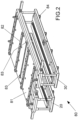
- FIG 2 a variant of the punching tool cassette 80 is shown.
- This comprises a cover plate 81 to which several T-bars 82 are attached.
- the punching tool cassette 80 is held in the stapler 1 by means of the T-bars 82 and is guided via the rack 10 ( Fig. 1 ) are moved.
- the punching tool cassette 80 is moved to the correct end position via stop elements 83 arranged on the cover plate 81, which is checked by a limit switch (not shown).
- the two punching tools 20, 30 are attached below the cover plate 81.
- each of the punching tools 20, 30 comprises several runners 84, which, for example, move when the punching tool cassette 80 is moved into a lifting slab 11 ( Fig. 1 ). If the lower tool part of the respective punching tool 20, 30 does not follow the lowering of the lifting slab 11 due to gravity after a stapling process, the lower tool part is pulled back into the lower end position by the lifting slab 11 through this connection.
Landscapes
- Engineering & Computer Science (AREA)
- Mechanical Engineering (AREA)
- Folding Of Thin Sheet-Like Materials, Special Discharging Devices, And Others (AREA)
- Punching Or Piercing (AREA)
Claims (8)
- Agrafeuse (1) pour relier une extrémité arrière d'une bande métallique sortante avec une extrémité avant d'une bande métallique entrante pour une installation de bande fonctionnant en continu, comprenant :- un premier outil de poinçonnage (20), conçu pour relier les bandes métalliques lorsque leurs épaisseurs se situent dans une première plage d'épaisseurs et/ou lorsque leurs résistances se situent dans une première plage de résistances, et- un deuxième outil de poinçonnage (30), conçu pour relier les bandes métalliques lorsque leurs épaisseurs se situent dans une deuxième plage d'épaisseurs et/ou leurs résistances se situent dans une deuxième plage de résistances, les deux plages d'épaisseurs et/ou de résistances étant différentes,les deux outils de poinçonnage (20, 30) étant disposés dans une cassette d'outils de poinçonnage (80), et la cassette d'outils de poinçonnage (80) étant déplaçable au moyen d'un dispositif de déplacement (60) à l'intérieur de l'agrafeuse (1), de sorte que le premier outil de poinçonnage (20) puisse être placé dans une position de poinçonnage (50) et le deuxième outil de poinçonnage (30) dans une position de stationnement (70) en dehors de l'agrafeuse (1), ou inversement,caractérisé en ce quele type de liaison utilisé est le stitching, etle premier outil de poinçonnage (20) présente un premier écart de coupe et le deuxième outil de poinçonnage (30) présente un deuxième écart de coupe, différent du premier.
- Agrafeuse (1) selon la revendication 1, où la première plage d'épaisseurs est de 0,2 à 2,5 mm et la deuxième plage d'épaisseurs est de 2,0 à 3,5 mm.
- Agrafeuse (1) selon la revendication 1 ou 2, où la première plage de résistances est de 20 MPa à 250 MPa pour l'aluminium et de 100 MPa à 350 MPa pour l'acier, et la deuxième plage de résistances est de 200 MPa à 600 MPa pour l'aluminium et de 300 MPa à 1000 MPa pour l'acier.
- Agrafeuse (1) selon l'une des revendications précédentes, où le premier outil de poinçonnage (20) présente un premier motif de poinçonnage et le deuxième outil de poinçonnage (30) présente un deuxième motif de poinçonnage, les deux motifs de poinçonnage étant différents.
- Installation de bande comprenant une agrafeuse (1) selon l'une des revendications 1 à 4.
- Procédé pour relier une extrémité arrière d'une bande métallique sortante avec une extrémité avant d'une bande métallique entrante dans une installation de bande fonctionnant en continu, où- les bandes métalliques, lorsque leurs épaisseurs se situent dans une première plage d'épaisseurs et/ou leurs résistances se situent dans une première plage de résistances, sont reliées avec un premier outil de poinçonnage (20), et- les bandes métalliques, lorsque leurs épaisseurs se situent dans une deuxième plage d'épaisseurs et/ou leurs résistances se situent dans une deuxième plage de résistances, sont reliées avec un deuxième outil de poinçonnage (30), les deux plages d'épaisseurs et/ou de résistances étant différentes, et les deux outils de poinçonnage (20, 30) étant disposés dans une cassette d'outils de poinçonnage (80), qui est déplaçable à l'intérieur de l'agrafeuse (1), caractérisé en ce quele type de liaison utilisé est le stitching et le changement d'outil entre le premier outil de poinçonnage (20) et le deuxième outil de poinçonnage (30) s'effectue de manière entièrement automatique, le premier outil de poinçonnage (20) présentant un premier écart de coupe et le deuxième outil de poinçonnage (30) présentant un deuxième écart de coupe, différent du premier.
- Procédé selon la revendication 6, où le changement d'outil s'effectue en cours de fonctionnement de la bande entre deux coutures de stitching.
- Procédé selon l'une des revendications 6 ou 7, où la liaison par coutures de stitching s'effectue en une seule rangée ou de préférence en deux rangées.
Applications Claiming Priority (2)
| Application Number | Priority Date | Filing Date | Title |
|---|---|---|---|
| DE102020200510.9A DE102020200510A1 (de) | 2020-01-16 | 2020-01-16 | Heftmaschine |
| PCT/EP2021/050747 WO2021144394A1 (fr) | 2020-01-16 | 2021-01-14 | Agrafeuse |
Publications (3)
| Publication Number | Publication Date |
|---|---|
| EP4090480A1 EP4090480A1 (fr) | 2022-11-23 |
| EP4090480C0 EP4090480C0 (fr) | 2024-11-20 |
| EP4090480B1 true EP4090480B1 (fr) | 2024-11-20 |
Family
ID=74187297
Family Applications (1)
| Application Number | Title | Priority Date | Filing Date |
|---|---|---|---|
| EP21700736.8A Active EP4090480B1 (fr) | 2020-01-16 | 2021-01-14 | Agrafeuse pour métal |
Country Status (5)
| Country | Link |
|---|---|
| US (1) | US11931791B2 (fr) |
| EP (1) | EP4090480B1 (fr) |
| CN (1) | CN114945433B (fr) |
| DE (1) | DE102020200510A1 (fr) |
| WO (1) | WO2021144394A1 (fr) |
Citations (2)
| Publication number | Priority date | Publication date | Assignee | Title |
|---|---|---|---|---|
| US3114151A (en) * | 1961-05-25 | 1963-12-17 | Production Machinery Corp | Strip stitcher |
| EP0927600B1 (fr) * | 1997-12-26 | 2005-04-06 | Murata Kikai Kabushiki Kaisha | Presse |
Family Cites Families (10)
| Publication number | Priority date | Publication date | Assignee | Title |
|---|---|---|---|---|
| DE668721C (de) | 1933-11-18 | 1938-12-09 | Fritz Grah Dipl Ing | Maschine zum Aneinanderheften von Blechen, Metallbaendern o. dgl. |
| DE1123879B (de) * | 1960-01-05 | 1962-02-15 | Thyssen Huette Ag | Verfahren und Anlage zur kontinuierlichen Entzunderung von Breitband in einer Durchlaufbeizanlage |
| DE1962129A1 (de) | 1969-12-11 | 1971-06-24 | Secor Ab | Vorrichtung zum Verbinden von Metallblechbaendern |
| US3670398A (en) | 1970-02-13 | 1972-06-20 | Carl H Minton | Method and apparatus for joining strip ends employing a stitcher assembly |
| IT1124987B (it) | 1979-11-16 | 1986-05-14 | Giovanni Giasini | Ppocedimento e macchina per l'esecuzione delle giunzioni testa-coda di nastri metallici di spessore sottile |
| EP0648556B1 (fr) * | 1990-05-01 | 1997-08-27 | Amada Company Limited | Dispositif de changement de matrice |
| EP1504896B1 (fr) * | 2001-12-25 | 2008-12-10 | Institute of Technology Precision Electrical Discharge Work's | Procede et systeme de production de lamines |
| JP5474889B2 (ja) * | 2011-08-09 | 2014-04-16 | 中外炉工業株式会社 | ストリップ材接続装置 |
| DE102012108161B4 (de) * | 2012-09-03 | 2016-09-22 | Bwg Bergwerk- Und Walzwerk-Maschinenbau Gmbh | Verfahren und Vorrichtung zum Verbinden von Metallbändern |
| EP2948259A1 (fr) * | 2013-01-22 | 2015-12-02 | ANDRITZ Sundwig GmbH | Dispositif permettant de relier des produits plats métalliques entrant successivement dans une installation de traitement de bandes |
-
2020
- 2020-01-16 DE DE102020200510.9A patent/DE102020200510A1/de not_active Withdrawn
-
2021
- 2021-01-14 EP EP21700736.8A patent/EP4090480B1/fr active Active
- 2021-01-14 WO PCT/EP2021/050747 patent/WO2021144394A1/fr not_active Ceased
- 2021-01-14 CN CN202180009624.8A patent/CN114945433B/zh active Active
- 2021-01-14 US US17/793,224 patent/US11931791B2/en active Active
Patent Citations (2)
| Publication number | Priority date | Publication date | Assignee | Title |
|---|---|---|---|---|
| US3114151A (en) * | 1961-05-25 | 1963-12-17 | Production Machinery Corp | Strip stitcher |
| EP0927600B1 (fr) * | 1997-12-26 | 2005-04-06 | Murata Kikai Kabushiki Kaisha | Presse |
Also Published As
| Publication number | Publication date |
|---|---|
| CN114945433B (zh) | 2025-05-13 |
| EP4090480C0 (fr) | 2024-11-20 |
| US20230064480A1 (en) | 2023-03-02 |
| WO2021144394A1 (fr) | 2021-07-22 |
| CN114945433A (zh) | 2022-08-26 |
| EP4090480A1 (fr) | 2022-11-23 |
| US11931791B2 (en) | 2024-03-19 |
| DE102020200510A1 (de) | 2021-07-22 |
Similar Documents
| Publication | Publication Date | Title |
|---|---|---|
| DE102012108161B4 (de) | Verfahren und Vorrichtung zum Verbinden von Metallbändern | |
| EP3020489B1 (fr) | Procédé et installation pour le raccordement de bandes métalliques | |
| DE69934444T2 (de) | Entgratverfahren | |
| EP2806986B1 (fr) | Procédé et dispositif destinés à relier deux extrémités de bandes métalliques | |
| EP2931449B1 (fr) | Procédé de réalisation d'une bande de matière continue | |
| WO2012156347A2 (fr) | Dispositif et procédé de fabrication d'un profilé métallique ou d'un feuillard soudé | |
| EP3495086B1 (fr) | Procédé et dispositif de fabrication d'un matériau composite en forme de bande | |
| DE102011080927A1 (de) | Verfahren und Vorrichtung zur Herstellung von ringförmigen Kupplungslamellen mit Verzahnung | |
| DE1627507A1 (de) | Maschine zum Miteinanderverbinden von zwei Materialstreifen | |
| EP4090480B1 (fr) | Agrafeuse pour métal | |
| WO2014114541A1 (fr) | Dispositif permettant de relier des produits plats métalliques entrant successivement dans une installation de traitement de bandes | |
| EP1495816B1 (fr) | Outil de pliage à segments de butée de la pièce réglables ainsi que machine à plier comprenant un tel outil de pliage | |
| DE2949095B1 (de) | Einrichtung zum Verbinden zweier Materialbaender | |
| EP3020488B1 (fr) | Procédé de raccordement de bandes métalliques | |
| EP1351783A1 (fr) | Dispositif de coupe transversale de bandes metalliques | |
| DE19824741A1 (de) | Verfahren und Vorrichtung zur Herstellung von Bundlagern | |
| DE2648447A1 (de) | Werkzeugmaschine mit zwei revolvertrommeln | |
| DE1911381C3 (de) | Vorrichtung zum Verschweißen von Blechen, insbesondere Bändern | |
| DE102005060252A1 (de) | Verfahren zur Herstellung eines Querträgers, insbesondere für ein Kraftfahrzeug | |
| EP4175784B1 (fr) | Méthode et installation de soudage de bandes métalliques | |
| DE10156087A1 (de) | Verfahren und Vorrichtung zur Herstellung und/oder Richten von Metallband mit variabler Querschnittsform | |
| DE69106306T2 (de) | Verfahren zum Verbinden von gewalzten Blechen. | |
| DE10016818C2 (de) | Verfahren und Anordnung zur Herstellung von in der Dicke variierenden Platinen aus Stahlblech | |
| DE19605724C2 (de) | Schneideinrichtung zum Schneiden von metallischem Bandmaterial | |
| DE10218575A1 (de) | Trennvorrichtung für bandförmiges Halbzeug mit Sollbruchstellen |
Legal Events
| Date | Code | Title | Description |
|---|---|---|---|
| STAA | Information on the status of an ep patent application or granted ep patent |
Free format text: STATUS: UNKNOWN |
|
| STAA | Information on the status of an ep patent application or granted ep patent |
Free format text: STATUS: THE INTERNATIONAL PUBLICATION HAS BEEN MADE |
|
| PUAI | Public reference made under article 153(3) epc to a published international application that has entered the european phase |
Free format text: ORIGINAL CODE: 0009012 |
|
| STAA | Information on the status of an ep patent application or granted ep patent |
Free format text: STATUS: REQUEST FOR EXAMINATION WAS MADE |
|
| 17P | Request for examination filed |
Effective date: 20220816 |
|
| AK | Designated contracting states |
Kind code of ref document: A1 Designated state(s): AL AT BE BG CH CY CZ DE DK EE ES FI FR GB GR HR HU IE IS IT LI LT LU LV MC MK MT NL NO PL PT RO RS SE SI SK SM TR |
|
| DAV | Request for validation of the european patent (deleted) | ||
| DAX | Request for extension of the european patent (deleted) | ||
| P01 | Opt-out of the competence of the unified patent court (upc) registered |
Effective date: 20230707 |
|
| STAA | Information on the status of an ep patent application or granted ep patent |
Free format text: STATUS: EXAMINATION IS IN PROGRESS |
|
| 17Q | First examination report despatched |
Effective date: 20230913 |
|
| GRAP | Despatch of communication of intention to grant a patent |
Free format text: ORIGINAL CODE: EPIDOSNIGR1 |
|
| STAA | Information on the status of an ep patent application or granted ep patent |
Free format text: STATUS: GRANT OF PATENT IS INTENDED |
|
| RAP3 | Party data changed (applicant data changed or rights of an application transferred) |
Owner name: SMS GROUP GMBH |
|
| INTG | Intention to grant announced |
Effective date: 20240814 |
|
| GRAS | Grant fee paid |
Free format text: ORIGINAL CODE: EPIDOSNIGR3 |
|
| GRAA | (expected) grant |
Free format text: ORIGINAL CODE: 0009210 |
|
| STAA | Information on the status of an ep patent application or granted ep patent |
Free format text: STATUS: THE PATENT HAS BEEN GRANTED |
|
| AK | Designated contracting states |
Kind code of ref document: B1 Designated state(s): AL AT BE BG CH CY CZ DE DK EE ES FI FR GB GR HR HU IE IS IT LI LT LU LV MC MK MT NL NO PL PT RO RS SE SI SK SM TR |
|
| REG | Reference to a national code |
Ref country code: GB Ref legal event code: FG4D Free format text: NOT ENGLISH |
|
| REG | Reference to a national code |
Ref country code: CH Ref legal event code: EP |
|
| REG | Reference to a national code |
Ref country code: DE Ref legal event code: R096 Ref document number: 502021005862 Country of ref document: DE |
|
| REG | Reference to a national code |
Ref country code: IE Ref legal event code: FG4D Free format text: LANGUAGE OF EP DOCUMENT: GERMAN |
|
| U01 | Request for unitary effect filed |
Effective date: 20241209 |
|
| P04 | Withdrawal of opt-out of the competence of the unified patent court (upc) registered |
Free format text: CASE NUMBER: APP_66591/2024 Effective date: 20241216 |
|
| U07 | Unitary effect registered |
Designated state(s): AT BE BG DE DK EE FI FR IT LT LU LV MT NL PT RO SE SI Effective date: 20241219 |
|
| U20 | Renewal fee for the european patent with unitary effect paid |
Year of fee payment: 5 Effective date: 20250128 |
|
| PG25 | Lapsed in a contracting state [announced via postgrant information from national office to epo] |
Ref country code: HR Free format text: LAPSE BECAUSE OF FAILURE TO SUBMIT A TRANSLATION OF THE DESCRIPTION OR TO PAY THE FEE WITHIN THE PRESCRIBED TIME-LIMIT Effective date: 20241120 Ref country code: IS Free format text: LAPSE BECAUSE OF FAILURE TO SUBMIT A TRANSLATION OF THE DESCRIPTION OR TO PAY THE FEE WITHIN THE PRESCRIBED TIME-LIMIT Effective date: 20250320 |
|
| PG25 | Lapsed in a contracting state [announced via postgrant information from national office to epo] |
Ref country code: ES Free format text: LAPSE BECAUSE OF FAILURE TO SUBMIT A TRANSLATION OF THE DESCRIPTION OR TO PAY THE FEE WITHIN THE PRESCRIBED TIME-LIMIT Effective date: 20241120 |
|
| PG25 | Lapsed in a contracting state [announced via postgrant information from national office to epo] |
Ref country code: NO Free format text: LAPSE BECAUSE OF FAILURE TO SUBMIT A TRANSLATION OF THE DESCRIPTION OR TO PAY THE FEE WITHIN THE PRESCRIBED TIME-LIMIT Effective date: 20250220 |
|
| PG25 | Lapsed in a contracting state [announced via postgrant information from national office to epo] |
Ref country code: GR Free format text: LAPSE BECAUSE OF FAILURE TO SUBMIT A TRANSLATION OF THE DESCRIPTION OR TO PAY THE FEE WITHIN THE PRESCRIBED TIME-LIMIT Effective date: 20250221 |
|
| PG25 | Lapsed in a contracting state [announced via postgrant information from national office to epo] |
Ref country code: PL Free format text: LAPSE BECAUSE OF FAILURE TO SUBMIT A TRANSLATION OF THE DESCRIPTION OR TO PAY THE FEE WITHIN THE PRESCRIBED TIME-LIMIT Effective date: 20241120 |
|
| PG25 | Lapsed in a contracting state [announced via postgrant information from national office to epo] |
Ref country code: RS Free format text: LAPSE BECAUSE OF FAILURE TO SUBMIT A TRANSLATION OF THE DESCRIPTION OR TO PAY THE FEE WITHIN THE PRESCRIBED TIME-LIMIT Effective date: 20250220 |
|
| PG25 | Lapsed in a contracting state [announced via postgrant information from national office to epo] |
Ref country code: SM Free format text: LAPSE BECAUSE OF FAILURE TO SUBMIT A TRANSLATION OF THE DESCRIPTION OR TO PAY THE FEE WITHIN THE PRESCRIBED TIME-LIMIT Effective date: 20241120 |
|
| PG25 | Lapsed in a contracting state [announced via postgrant information from national office to epo] |
Ref country code: SK Free format text: LAPSE BECAUSE OF FAILURE TO SUBMIT A TRANSLATION OF THE DESCRIPTION OR TO PAY THE FEE WITHIN THE PRESCRIBED TIME-LIMIT Effective date: 20241120 |
|
| PG25 | Lapsed in a contracting state [announced via postgrant information from national office to epo] |
Ref country code: CZ Free format text: LAPSE BECAUSE OF FAILURE TO SUBMIT A TRANSLATION OF THE DESCRIPTION OR TO PAY THE FEE WITHIN THE PRESCRIBED TIME-LIMIT Effective date: 20241120 |
|
| REG | Reference to a national code |
Ref country code: CH Ref legal event code: PL |
|
| PG25 | Lapsed in a contracting state [announced via postgrant information from national office to epo] |
Ref country code: MC Free format text: LAPSE BECAUSE OF FAILURE TO SUBMIT A TRANSLATION OF THE DESCRIPTION OR TO PAY THE FEE WITHIN THE PRESCRIBED TIME-LIMIT Effective date: 20241120 |
|
| PLBE | No opposition filed within time limit |
Free format text: ORIGINAL CODE: 0009261 |
|
| STAA | Information on the status of an ep patent application or granted ep patent |
Free format text: STATUS: NO OPPOSITION FILED WITHIN TIME LIMIT |
|
| PG25 | Lapsed in a contracting state [announced via postgrant information from national office to epo] |
Ref country code: CH Free format text: LAPSE BECAUSE OF NON-PAYMENT OF DUE FEES Effective date: 20250131 |
|
| 26N | No opposition filed |
Effective date: 20250821 |
|
| GBPC | Gb: european patent ceased through non-payment of renewal fee |
Effective date: 20250220 |
|
| PG25 | Lapsed in a contracting state [announced via postgrant information from national office to epo] |
Ref country code: GB Free format text: LAPSE BECAUSE OF NON-PAYMENT OF DUE FEES Effective date: 20250220 |
|
| PG25 | Lapsed in a contracting state [announced via postgrant information from national office to epo] |
Ref country code: IE Free format text: LAPSE BECAUSE OF NON-PAYMENT OF DUE FEES Effective date: 20250114 |
|
| U20 | Renewal fee for the european patent with unitary effect paid |
Year of fee payment: 6 Effective date: 20260129 |