EP4090542B1 - Procédé de production d'une jante de véhicule automobile en aluminium ou en alliage d'aluminium pour une roue d'un véhicule automobile et jante de véhicule automobile correspondante - Google Patents
Procédé de production d'une jante de véhicule automobile en aluminium ou en alliage d'aluminium pour une roue d'un véhicule automobile et jante de véhicule automobile correspondante Download PDFInfo
- Publication number
- EP4090542B1 EP4090542B1 EP20808404.6A EP20808404A EP4090542B1 EP 4090542 B1 EP4090542 B1 EP 4090542B1 EP 20808404 A EP20808404 A EP 20808404A EP 4090542 B1 EP4090542 B1 EP 4090542B1
- Authority
- EP
- European Patent Office
- Prior art keywords
- rim
- motor vehicle
- casting
- vehicle rim
- air conveying
- Prior art date
- Legal status (The legal status is an assumption and is not a legal conclusion. Google has not performed a legal analysis and makes no representation as to the accuracy of the status listed.)
- Active
Links
Images
Classifications
-
- B—PERFORMING OPERATIONS; TRANSPORTING
- B60—VEHICLES IN GENERAL
- B60B—VEHICLE WHEELS; CASTORS; AXLES FOR WHEELS OR CASTORS; INCREASING WHEEL ADHESION
- B60B3/00—Disc wheels, i.e. wheels with load-supporting disc body
- B60B3/06—Disc wheels, i.e. wheels with load-supporting disc body formed by casting
-
- B—PERFORMING OPERATIONS; TRANSPORTING
- B22—CASTING; POWDER METALLURGY
- B22D—CASTING OF METALS; CASTING OF OTHER SUBSTANCES BY THE SAME PROCESSES OR DEVICES
- B22D18/00—Pressure casting; Vacuum casting
- B22D18/06—Vacuum casting, i.e. making use of vacuum to fill the mould
-
- B—PERFORMING OPERATIONS; TRANSPORTING
- B60—VEHICLES IN GENERAL
- B60B—VEHICLE WHEELS; CASTORS; AXLES FOR WHEELS OR CASTORS; INCREASING WHEEL ADHESION
- B60B19/00—Wheels not otherwise provided for or having characteristics specified in one of the subgroups of this group
- B60B19/10—Wheels not otherwise provided for or having characteristics specified in one of the subgroups of this group with cooling fins
-
- B—PERFORMING OPERATIONS; TRANSPORTING
- B60—VEHICLES IN GENERAL
- B60B—VEHICLE WHEELS; CASTORS; AXLES FOR WHEELS OR CASTORS; INCREASING WHEEL ADHESION
- B60B3/00—Disc wheels, i.e. wheels with load-supporting disc body
- B60B3/02—Disc wheels, i.e. wheels with load-supporting disc body with a single disc body integral with rim
-
- B—PERFORMING OPERATIONS; TRANSPORTING
- B60—VEHICLES IN GENERAL
- B60B—VEHICLE WHEELS; CASTORS; AXLES FOR WHEELS OR CASTORS; INCREASING WHEEL ADHESION
- B60B3/00—Disc wheels, i.e. wheels with load-supporting disc body
- B60B3/10—Disc wheels, i.e. wheels with load-supporting disc body apertured to simulate spoked wheels
-
- B—PERFORMING OPERATIONS; TRANSPORTING
- B60—VEHICLES IN GENERAL
- B60B—VEHICLE WHEELS; CASTORS; AXLES FOR WHEELS OR CASTORS; INCREASING WHEEL ADHESION
- B60B2310/00—Manufacturing methods
- B60B2310/20—Shaping
- B60B2310/202—Shaping by casting
-
- B—PERFORMING OPERATIONS; TRANSPORTING
- B60—VEHICLES IN GENERAL
- B60B—VEHICLE WHEELS; CASTORS; AXLES FOR WHEELS OR CASTORS; INCREASING WHEEL ADHESION
- B60B2360/00—Materials; Physical forms thereof
- B60B2360/10—Metallic materials
- B60B2360/104—Aluminum
-
- B—PERFORMING OPERATIONS; TRANSPORTING
- B60—VEHICLES IN GENERAL
- B60B—VEHICLE WHEELS; CASTORS; AXLES FOR WHEELS OR CASTORS; INCREASING WHEEL ADHESION
- B60B2900/00—Purpose of invention
- B60B2900/50—Improvement of
- B60B2900/513—Cooling, e.g. of brakes
-
- Y—GENERAL TAGGING OF NEW TECHNOLOGICAL DEVELOPMENTS; GENERAL TAGGING OF CROSS-SECTIONAL TECHNOLOGIES SPANNING OVER SEVERAL SECTIONS OF THE IPC; TECHNICAL SUBJECTS COVERED BY FORMER USPC CROSS-REFERENCE ART COLLECTIONS [XRACs] AND DIGESTS
- Y02—TECHNOLOGIES OR APPLICATIONS FOR MITIGATION OR ADAPTATION AGAINST CLIMATE CHANGE
- Y02T—CLIMATE CHANGE MITIGATION TECHNOLOGIES RELATED TO TRANSPORTATION
- Y02T10/00—Road transport of goods or passengers
- Y02T10/80—Technologies aiming to reduce greenhouse gasses emissions common to all road transportation technologies
- Y02T10/86—Optimisation of rolling resistance, e.g. weight reduction
Definitions
- the invention relates to a method for producing a motor vehicle rim made of aluminum or an aluminum alloy for a wheel of a motor vehicle, wherein the motor vehicle rim has a rim base defined on opposite sides by an outer flange and an inner flange, a hub with a central recess and a bolt circle, and a rim center connecting the rim base and the hub, particularly engaging the rim base eccentrically in longitudinal section.
- the invention further relates to a motor vehicle rim.
- the state of the art includes, for example, the publication EP 0 301 472 B1 This describes a manufacturing process for light metal cast wheels for passenger cars, using a near-eutectic refined AISi alloy which, in addition to Al, contains a weight fraction of 9.5% to 12.5% silicon and alloying components such as a maximum of 0.2% iron, a maximum of 0.05% manganese, a maximum of 0.1% titanium, a maximum of 0.03% copper, a maximum of 0.05% zinc, and a maximum of 0.05% each and a total of a maximum of 0.15% other impurities.
- the wheels are removed from the casting mold and cooled.
- the alloy contains a minimum of 0.05% to a maximum of 0.15% magnesium by weight, and that the wheels are cooled from a temperature – measured on their surface – of at least 380°C in interior areas or areas with mass concentrations such as Hub and bowl of wheels are quenched in water immediately after removal from the mold.
- the publication describes DE 20 2014 100 377 U1 a vehicle wheel having a wheel body and a plurality of rim blades coupled to at least one side surface of the wheel body, each of the rim blades having an airflow guide portion and an airflow auxiliary portion, the airflow guide portion and the airflow auxiliary portion being arranged in a front and rear side on the rim blade.
- the printed matter DE 40 27 355 C2 also shows a double disc structure for motor vehicle wheels made of light metal alloy, comprising: first and second wheel discs formed separately from one another and detachably secured to one another at their hubs by a plurality of first screw clamping devices and at their peripheral edges by a plurality of second screw clamping devices, and rotatable as a unitary double wheel disc together with the wheel rim provided thereon; and ventilation holes formed in the corresponding intermediate regions between the hub and the peripheral edge of the two wheel discs, wherein the ventilation holes of the second wheel disc differ in size, shape, and distribution from the ventilation holes of the first wheel disc, and wherein the intermediate regions and the wheel axis form a triangular configuration in cross-section.
- US 8 651 584 B2 Furthermore, a motor vehicle rim with air conveying elements in the rim well area is known.
- the motor vehicle rim is produced in one piece and continuously in a casting mold by die-casting a casting material, wherein the motor vehicle rim is formed during die-casting with at least one air conveying element arranged to convey air in the axial direction with respect to a longitudinal center axis of the motor vehicle rim relative to an imaginary plane perpendicular to the longitudinal center axis and/or at least one surface enlargement element running in the circumferential direction along a circular line.
- the motor vehicle rim is typically a component of the wheel of the motor vehicle, with the motor vehicle having multiple wheels, each of which has such a motor vehicle rim.
- the motor vehicle is in the form of a motor vehicle and therefore has more than two wheels, in particular exactly four wheels.
- the motor vehicle rim is explicitly intended and designed for use on such a motor vehicle designed as a motor vehicle.
- the motor vehicle rim is therefore not a generic motor vehicle rim, but is intended for use on the motor vehicle and designed accordingly.
- the essential components of a motor vehicle rim are the rim well, the rim center, and the hub.
- the rim well and the hub are connected to one another via the rim center, with at least the rim well, the rim center, and the hub being formed integrally and from the same material.
- the rim well, the rim center, and the hub are formed simultaneously, namely during a single manufacturing step. Therefore, it is not intended to manufacture the rim well, the rim center, and the hub separately and subsequently attach them to one another. Rather, they are manufactured jointly, namely by pressure-casting the casting material in the mold.
- the motor vehicle rim has a longitudinal center axis, which corresponds in particular to a longitudinal center axis of the hub and preferably with a later axis of rotation of the wheel coincides or at least almost coincides.
- the rim well Viewed in the axial direction with respect to this longitudinal center axis, the rim well is delimited on opposite sides by the outer flange and the inner flange.
- the outer flange and the inner flange are therefore located on opposite sides of the rim well and enclose a tire receiving area of the motor vehicle rim between them when viewed in longitudinal section with respect to the longitudinal center axis.
- the tire receiving area serves to accommodate a tire which, together with the motor vehicle rim, forms the wheel.
- the tire receiving area is delimited in the radial direction inwards by the rim well and in the axial direction on opposite sides by the outer flange and the inner flange.
- the entire motor vehicle rim is delimited in the axial direction or, as viewed in longitudinal section, in a first direction by the outer flange and in a second direction by the inner flange, such that the outer flange and the inner flange define an overall extension of the motor vehicle rim in the axial direction, corresponding to a width of the motor vehicle rim.
- the outer flange and the inner flange are in the form of a radial projection extending from the rim well and outward in a radial direction, again relative to the longitudinal center axis of the vehicle rim.
- the outer flange and the inner flange are also formed integrally and from the same material as the rest of the vehicle rim, in particular the rim well, the center of the hub, and the hub. They are therefore formed simultaneously with the rest of the rim during the die-casting process.
- the hub has a center recess and a bolt circle.
- the center recess is a central recess for accommodating a wheel hub. of the motor vehicle, to which the wheel is attached during assembly.
- the wheel hub is rotatably mounted on the wheel carrier via the wheel bearing.
- the bolt circle consists of several holes arranged along an imaginary circle, each of which serves to accommodate a fastener used to attach the vehicle rim to the wheel hub.
- the fastener is in the form of a screw, bolt, or the like, for example.
- the rim well and the hub are connected to each other via the rim center.
- the rim center is therefore located between the rim well and the hub in the radial direction relative to the longitudinal center axis. It extends radially from the hub to the rim well.
- the rim center has several spokes that are arranged or formed spaced apart from one another in the circumferential direction.
- the rim center can also be continuous in the circumferential direction, in particular completely.
- the rim center preferably engages the rim well off-center in the axial direction or, as viewed in longitudinal section, this means that it merges into the rim well in the axial direction away from a center point of the rim well.
- the rim center preferably engages at a distance from the center point of the rim well in the axial direction that is at least 10%, at least 20%, at least 30%, at least 40% or more based on the total extension of the rim well in the axial direction. For example, the rim center merges into the rim well at the end of the rim well as viewed in the axial direction.
- the rim center merges into the rim well in overlap with the outer flange or the inner flange, preferably the former. Due to the eccentric engagement of the rim center with the rim base, the rim center is subjected not only to a radial force after the wheel is mounted on the vehicle, but also to a bending moment in the axial direction, or in an imaginary plane that includes the longitudinal center axis of the vehicle rim. This has previously required a correspondingly solid rim center, requiring a high level of material input. Alternatively, the rim center can also engage centrally on the rim base and/or the hub.
- the rim well preferably has a greater extension in the axial direction than the rim center and the hub.
- the axial extension of the rim well is greater than the axial extension of the hub, which in turn is greater than the axial extension of the rim center.
- the axial extension of the hub relative to the axial extension of the rim well is at most 50%, at most 40%, at most 30%, at most 25%, or at most 20%.
- the axial extension of the rim center relative to the axial extension of the rim well is, for example, at most 25%, at most 20%, at most 15%, at most 10%, or at most 5%.
- the dimensions mentioned create a receptacle for the wheel hub and/or a brake disc attached to the wheel, which receptacle is encompassed by the rim base, the wheel hub and/or the brake disc being present in this receptacle after the wheel has been mounted on the motor vehicle.
- the motor vehicle rim is made entirely of the same material, namely aluminum or, preferably, an aluminum alloy. This material is processed by die casting. During die casting, a mold is used to form the motor vehicle rim, and thus at least the rim base including the outer flange and the inner flange, the rim center, and the hub.
- the center recess which can also be referred to as the wheel hub receptacle, is also preferably formed, at least partially, during die casting.
- Die casting can be carried out at normal pressure or as vacuum die casting.
- Vacuum die casting is characterized by the fact that the casting mold is at least partially evacuated before and/or during the introduction of the casting material into the mold. This means that the casting mold is subjected to a negative pressure before and/or during the introduction of the casting material. is applied.
- the negative pressure is understood to be a pressure that is lower than the injection pressure at which the casting material is introduced into the casting mold and/or the ambient pressure in the external environment of the casting mold.
- the negative pressure relative to the external pressure is at most 50%, at most 25%, at most 10%, or at most 5%.
- the residual pressure is between 50 mbar and 200 mbar.
- the residual pressure is understood to be the absolute pressure in the casting mold.
- the casting mold is evacuated, for example, using a vacuum source that is placed in flow communication with the casting mold for this purpose.
- the casting mold is evacuated before the casting material is introduced.
- the casting material is introduced when, and in particular only when, a certain vacuum or residual pressure is reached in the casting mold.
- it can be provided to evacuate the casting mold during the introduction of the casting material, i.e. to maintain the flow connection between the vacuum source and the casting mold during the introduction of the casting material into the casting mold and to continue operating the vacuum source to evacuate the casting mold. This allows particularly delicate structures of the motor vehicle rim to be produced.
- the casting mold is provided to first seal the casting mold by means of at least one seal, for example by means of a sealing cord, in particular a silicone sealing cord.
- the casting material is then metered into a casting chamber, which is fluidically connected to the casting mold.
- the casting chamber is at least temporarily fluidically connected to a crucible in which the molten casting material is stored.
- the casting mold is then subjected to negative pressure, and the casting material located in the casting chamber is forced into the casting mold, in particular by means of a pressurized piston.
- the flow connection between the casting chamber and the crucible exists simultaneously, in particular continues. This means that the casting chamber is also evacuated during the introduction of the casting material.
- the motor vehicle rim has at least one air conveying element and/or at least one surface enlargement element.
- the air conveying element in this case, exactly one air conveying element or several air conveying elements can be implemented. Additionally or alternatively, exactly one surface enlargement element or several surface enlargement elements can be formed on the motor vehicle rim. If reference is made to the air conveying element in the context of this description, the statements always apply to the at least one air conveying element or each of the several air conveying elements. The same applies to statements regarding the surface enlargement element, which likewise always apply to the at least one surface enlargement element or each of the several surface enlargement elements.
- the at least one air conveying element is implemented on the motor vehicle rim, but not the surface enlargement element.
- the surface enlargement element is present on the motor vehicle rim, but not the air conveying element.
- both the air conveying element and the surface enlargement element it is particularly advantageous for both the air conveying element and the surface enlargement element to be formed on the motor vehicle rim.
- the air conveying element and the surface enlargement element are mentioned in this description, the statements always apply to the respective element present.
- the joint mention of the air conveying element and the surface enlargement element does not mean that both elements are actually present, although this can of course be the case.
- the air conveying element and the surface enlargement element are formed integrally and continuously with the vehicle rim. They are formed together with the vehicle rim during the die-casting process. Therefore, it is not intended to manufacture the air conveying element and the surface enlargement element independently of the vehicle rim and subsequently attach them to it. This enables particularly efficient production of the vehicle rim.
- the air conveying element is designed in such a way that, when the motor vehicle rim rotates about its longitudinal center axis, it exerts a conveying effect on the air surrounding the motor vehicle rim.
- the air conveying element conveys the air in an axial direction relative to the longitudinal center axis, for example from an inner side of the motor vehicle rim towards an outer side of the rim or vice versa.
- an air flow is to be created in an axial direction when the motor vehicle is in operation, i.e. when the motor vehicle rim rotates, which air flow brings about efficient cooling of the motor vehicle rim and/or the at least one further element.
- warm air can be discharged from the further element by means of the air conveying element, in particular by conveying the warm air present on the inner side of the rim towards the outer side of the rim or by discharging it onto the outer side of the rim.
- the rim inner side is understood to mean in particular a side of the motor vehicle rim which faces the wheel carrier, whereas the rim outer side is the side of the motor vehicle rim which faces away from the wheel carrier.
- the additional element such as the brake disc
- the additional element is typically located on the inside of the rim; for example, it is at least partially encompassed by the rim base, so that it is ultimately located within the vehicle rim.
- the additional element is connected to the vehicle rim in a rotationally fixed manner after the vehicle rim has been mounted on the vehicle.
- the air conveying effect of the air conveying element is achieved by positioning the air conveying element relative to the imaginary plane.
- the plane is perpendicular to the longitudinal center axis of the vehicle rim.
- the air conveying element can generally be plate-shaped in cross-section and exert its air conveying effect solely due to its angle.
- the air conveying element is airfoil-shaped in cross-section, i.e., has a flow-oriented profile. This type of air conveying element achieves particularly efficient and effective air conveyance.
- the motor vehicle rim has at least one surface enlargement element.
- the surface enlargement element also ultimately serves to dissipate heat. This is achieved by enlarging the surface of the motor vehicle rim, so that the heat is dissipated or removed from the motor vehicle rim via the surface enlargement element due to natural convention and/or forced convection.
- the surface enlargement element extends in the circumferential direction along the imaginary circular line, so that the surface enlargement element is annular at least in some regions, in particular only in some regions or continuously.
- the surface enlargement element encompasses the longitudinal center axis of the motor vehicle rim at least partially, for example only partially or completely. In particular, the surface enlargement element extends in the circumferential direction over at least 30°, at least 60°, at least 90° or at least 180°.
- a particularly preferred embodiment of the motor vehicle rim is one in which the at least one surface enlargement element is present in addition to the at least one air conveying element.
- the air conveying element and the surface enlargement element are preferably arranged and designed such that the air flow caused by the air conveying element during the rotational movement of the motor vehicle rim flows against and/or over the surface enlargement element.
- Such a configuration of the motor vehicle rim enables a particularly effective heat dissipation.
- the surface enlargement element and the air conveying element are connected or attached to each other.
- the described process for manufacturing car rims enables simple, fast, and cost-effective production of the rim, which can also have an extremely delicate structure and is also designed and constructed for effective heat dissipation. Rapid production is achieved in particular through die casting, which fills the mold much faster than with permanent mold casting or low-pressure casting, which is normally used to manufacture car rims. Overall, die casting allows the cycle time for car rims to be significantly increased, allowing a larger number of car rims to be produced in the same amount of time. The solidification time is also significantly shorter for die casting than for permanent mold casting.
- the motor vehicle rim has, at least in some regions, a small wall thickness of at most 15 mm and/or a curvature with a small radius of curvature of at most 4 mm and/or a demoulding surface which runs in the axial direction and in the radial direction and/or in the axial direction and in the tangential direction with respect to a longitudinal central axis of the motor vehicle rim and which lies entirely in an imaginary plane, wherein the plane encloses an angle with the longitudinal central axis which is more than 0° and at most 4°.
- This preferably applies to the air conveying element and/or the surface enlargement element. It can therefore be provided that the air conveying element and/or the surface enlargement element have the small wall thickness and/or the curvature with the small radius of curvature, and/or that the demoulding surface is formed on them.
- the car rim produced by die casting is generally characterized by a particularly low wall thickness and/or a Curvature with a particularly small radius of curvature and/or by the presence of the demolding surface.
- the wall thickness is understood to mean the thickness of the wall of the motor vehicle rim at at least one point.
- the small wall thickness can therefore be present, for example, at the rim well, the outer flange, the inner flange, the rim center and/or the hub.
- the small wall thickness is particularly preferably present at the rim center.
- the small wall thickness represents the greatest wall thickness, for example the greatest wall thickness of the outer flange, the greatest wall thickness of the inner flange and/or the greatest wall thickness of the rim center. Of course, it can also be the greatest wall thickness of the rim well and/or the hub.
- the small wall thickness is at most 15 mm, at most 10 mm, at most 7.5 mm or at most 5 mm, but is preferably smaller. Thus, it is, for example, at most 4 mm, at most 3 mm, at most 2 mm or at most 1.5 mm. Conversely, the small wall thickness is particularly preferably at least 1.5 mm or at least 2 mm. In other words, the small wall thickness is, for example, at least 1.5 mm and at most 5 mm, at least 1.5 mm and at most 4 mm, at least 1.5 mm and at most 3 mm, at least 1.5 mm and at most 2 mm or approximately or exactly 1.5 mm. However, it can also be at least 2 mm and at most 5 mm, at least 2 mm and at most 4 mm, at least 2 mm and at most 3 mm or exactly 2 mm.
- the curvature has a small radius of curvature.
- the curvature is a curvature of an outer surface or outer peripheral surface of the motor vehicle rim.
- the outer surface defines the outer boundary of a wall of the motor vehicle rim.
- the curvature can be present at any location on the motor vehicle rim, for example, at the rim well, the outer flange, the inner flange, the rim center, and/or the hub.
- the curvature is, in particular, a transitional curvature between two surfaces that—seen in section—are angled toward each other and are, for example, flat surfaces.
- the curvature preferably extends over an angle of at least 30°, at least 45°, at least 60°, or at least 90°.
- the curvature has a small radius of curvature, which is at most 4 mm, but is preferably smaller.
- the small radius of curvature corresponds to a radius of curvature of at most 3 mm, at most 2 mm, at most 1.5 mm, or at most 1 mm.
- the radius of curvature can additionally be at least 0.25 mm, at least 0.5 mm, or at least 0.75 mm.
- the motor vehicle rim can have a demolding surface.
- the demolding surface is understood to be a flat surface that lies directly against the casting mold during die casting and along which the motor vehicle rim is demolded from the casting mold after die casting.
- the demolding surface extends at least in the axial direction and in the radial direction and/or - additionally or alternatively - in the axial direction and in the tangential direction, in each case with respect to the longitudinal center axis of the motor vehicle rim. In any case, the demolding surface extends in two mutually perpendicular directions and thus lies entirely in the imaginary plane.
- Demolding of the car rim occurs in the same direction.
- a part of the mold is displaced in the direction of the longitudinal center axis, i.e., in the axial direction, to open the mold and remove the car rim from the mold.
- a mold surface of the mold that rests against and forms the demolding surface during die casting is displaced along the longitudinal center axis after die casting.
- the demolding angle i.e., the angle between the demolding surface and the longitudinal center axis, must be at least 5° to ensure proper demolding.
- the angle between the demolding surface or between the plane completely accommodating the demolding surface and the longitudinal center axis is between infinitesimally more than 0° and 4°, inclusive of these values. It can therefore be provided that the demolding surface runs almost parallel to the longitudinal center axis, so that an almost parallel displacement of the casting mold surface and the demolding surface occurs during demolding.
- the angle of 0° is understood to mean that the plane and the longitudinal center axis lie within one another or run parallel to one another.
- the angle is, for example, at least 0.5°, at least 1°, or at least 1.5°.
- a maximum angle of 4° is provided. For example, the angle is at most 3°, at most 2.0°, at most 1.5°, at most 1.0°, or at most 0.5°.
- the smaller angles of 2.0° and less are preferred.
- the air conveying element and/or the surface enlargement element have the small wall thickness and/or the curvature with the small radius of curvature and/or the demolding surface.
- the air conveying element and the surface enlargement element are particularly preferably designed with at least the small wall thickness, which is particularly preferably at most 7.5 mm, at most 5 mm, or at most 2.5 mm.
- the air conveying element extends from the hub to the rim well and is manufactured with a radial load-bearing capacity that corresponds to at least 2.5%, at least 5%, at least 7.5%, or at least 10% of the radial load-bearing capacity of the rim center.
- the load-bearing capacity refers to the radial load-bearing capacity between the hub and the rim well.
- the air conveying element extends radially from the hub to the rim base.
- the load-bearing capacity of the air conveying element should be less than the load-bearing capacity of the rim center. However, the load-bearing capacity should at least correspond to one of the specified values.
- the load-bearing capacity of the rim center refers to the load-bearing capacity of the entire rim center, regardless of whether it is continuous or has multiple spokes. If multiple spokes are assigned to the rim center, the air conveying element has, for example, a load-bearing capacity in the radial direction that corresponds to at least 25%, at least 50%, or at least 75% of the load-bearing capacity of one of the spokes. Additionally or alternatively, however, the load-bearing capacity of the air conveying element is at most 75%, at most 50%, or at most 25% of the load-bearing capacity of one of the spokes. For example, the load-bearing capacity of the air conveying element is at least 25% and at most 75%, at least 25% and at most 50%, or exactly or approximately 25% of the load-bearing capacity of one of the spokes.
- each of the multiple spokes is assigned at least one air conveying element, in particular exactly one air conveying element.
- the respective air conveying element is arranged on the corresponding spoke.
- the air conveying element extends from the respective spoke and is continuously connected to the spoke in the radial direction from the inside to the outside.
- the number of air conveying elements corresponds to the number of spokes.
- the number of air conveying elements is greater or smaller than the number of spokes.
- each of the spokes can also be assigned a plurality of air conveying elements, which are arranged on the respective spoke at a distance from one another in the circumferential direction. This makes it possible to achieve particularly effective heat introduction.
- the rim center is formed with a plurality of spokes spaced apart from one another in the circumferential direction with respect to a longitudinal center axis of the motor vehicle rim.
- the rim center is therefore not solid and continuous in the circumferential direction, but is composed of the plurality of spokes arranged spaced apart from one another in the circumferential direction.
- each of the plurality of spokes extends radially from the hub to the rim well, thus connecting the hub and the rim well. For example, at least three spokes, at least four spokes, at least five spokes, or at least six spokes are provided.
- each of the spokes extends circumferentially over a maximum of 30° or less, preferably a maximum of 15° or a maximum of 10°.
- the spokes have a constant extension in the circumferential direction, i.e. starting from the rim well up to the hub.
- branching of at least one of the spokes or several or each of the spokes can also be provided, so that the respective spoke is divided into several partial spokes.
- the spoke initially extends radially outwards from the hub and divides at a division point into several partial spokes which run parallel to one another, in particular in the circumferential direction. After the division point, the partial spokes thus run spaced apart from one another up to the rim well and engage thereat at a distance from one another.
- a longitudinal center axis of at least one of the spokes intersects the longitudinal center axis of the motor vehicle rim or is even perpendicular to it. This achieves a particularly optimal introduction of force from the center of the rim or from the spokes into the hub.
- the motor vehicle rim is manufactured in some regions with a first wall thickness of more than 15 mm, in particular at least 17.5 mm or at least 20 mm, and in some regions with a second wall thickness corresponding to the low wall thickness.
- the motor vehicle rim is manufactured in some regions with a first wall thickness of more than 5 mm, in particular at least 7.5 mm or at least 10 mm, but at most 20 mm, and in some regions with a second wall thickness corresponding to the low wall thickness.
- the second wall thickness is preferably at least 1.5 mm or at least 2 mm and at most 15 mm, at most 10 mm, at most 7.5 mm or at most 5 mm, preferably at most 3 mm, at most 2.5 mm or at most 2 mm.
- the motor vehicle rim therefore does not have the low wall thickness completely throughout, but is composed of several parts, some of which have the first wall thickness and others the second wall thickness.
- the first wall thickness is generally greater than the second wall thickness, for example, by a factor of at least 1.5, at least 2.0, or at least 2.5.
- the first wall thickness and the second wall thickness are both implemented in the center of the rim.
- a further development of the invention provides that the low wall thickness is used in a region located in the circumferential direction between two spokes, so that the two spokes are connected to one another via an intermediate storage element produced during die casting, which has the low wall thickness at least in some regions, in particular continuously.
- the region located in the circumferential direction between the two spokes can also be referred to as the intermediate spoke region.
- the intermediate spoke region extends in the circumferential direction between the two spokes and is radially inwardly delimited by the Hub and radially outwardly bounded by the rim well. In this respect, the interspoke area is completely enclosed on the vehicle rim.
- the intermediate spoke area is now at least partially or even completely provided with the intermediate spoke element, so that the area between the two spokes is at least partially or even completely closed with the intermediate spoke element.
- the intermediate spoke element has the low wall thickness.
- the two spokes can have a greater wall thickness than the low wall thickness, for example a wall thickness corresponding to the first wall thickness.
- the two spokes are designed with the low wall thickness.
- the low wall thickness is also used for the intermediate spoke element, in particular continuously, or a wall thickness that is less than the low wall thickness.
- the intermediate spoke element helps achieve excellent aerodynamic properties for the motor vehicle rim.
- the interspoke element is configured to completely fill an area that is bounded circumferentially by the two spokes, radially inward by the hub, and radially outward by the rim base. Such a configuration has already been mentioned above.
- the interspoke element thus completely fills the interspoke area or completely seals it. This achieves particularly good aerodynamic properties.
- the air conveying element and/or the surface enlargement element are formed starting from the rim center, in particular from the at least one spoke.
- the air conveying element or the surface enlargement element extends from the rim center in the axial direction, so that on its side facing away from the rim center, it has a free end
- the free end can be in the form of a straight line or curved, in particular with a curvature that is constant or changing in the radial direction from the inside to the outside or vice versa.
- the free end of the surface enlargement element is preferably circular or at least partially circular.
- the surface enlargement element is preferably hollow-cylindrical, in particular hollow-circular-cylindrical.
- the at least one air conveying element is preferably attached to at least one of the spokes. It has already been pointed out that the plurality of spokes can also be assigned several air conveying elements.
- the surface enlargement element preferably connects several spokes to one another, thus engaging several of the spokes, in particular all of the spokes. In the latter case, it is preferably continuous in the circumferential direction, thus completely encompassing the longitudinal center axis of the motor vehicle rim. The described configuration enables a particularly high cooling effect of the motor vehicle rim.
- the invention provides that the air conveying element and/or the surface enlargement element are formed on the inside of the motor vehicle rim.
- the air conveying element or the surface enlargement element extends in the axial direction, i.e., viewed in longitudinal section, in the direction of the inner flange.
- the air conveying element or the surface enlargement element are preferably completely accommodated in the motor vehicle rim, also viewed in longitudinal section.
- the air conveying element and/or the surface enlargement element are arranged such that they are not visible or only barely visible from the outside of the rim under normal observation. This achieves an excellent visual impression of the motor vehicle rim despite the air conveying element or the surface enlargement element.
- the surface enlargement element is formed starting from the air conveying element.
- the surface enlargement element thus extends in the circumferential direction starting from the air conveying element. For example, it extends in turn to the air conveying element, so that the surface enlargement element engages the air conveying element on both sides.
- the surface enlargement element extends starting from one of several air conveying elements to another of the several air conveying elements. This allows a particularly thin wall thickness of the air conveying element to be achieved because it is supported by the surface enlargement element.
- a further development of the invention provides that the air conveying element is designed to extend radially from the hub to the rim base relative to the longitudinal center axis. This has already been pointed out above.
- the air conveying element viewed in longitudinal section, is designed with an extension in the axial direction that corresponds at most to the extension of the rim center in the same direction or is at most 50%, at most 40%, at most 30%, at most 20%, or at most 10% greater than this.
- the air conveying element has, for example, an extension in the axial direction that corresponds at least 50%, at least 75%, or at least 100% to the extension of the rim center in this direction.
- the casting mold used in the die casting is a component of a die casting tool, in particular a two-plate die casting tool or a three-plate die casting tool, and the casting material is introduced into the casting mold through at least one injection opening, in particular through several injection openings.
- the three-plate die casting tool is characterized in that its sprue system is located in a different plane than the injection opening.
- the three-plate die casting tool has three plates, namely a first plate, a second plate, and a third plate. Between the first plate and the second plate, there is preferably at least one sprue channel, via which the injection opening is fluidly connected to an inlet opening.
- the casting material is fed into the casting mold through the inlet opening.
- the motor vehicle rim is formed between the second plate and the third plate. This means that the second plate and the third plate form the actual casting mold.
- the at least one sprue and the motor vehicle rim to be produced are located on opposite sides of the second plate.
- the casting material is preferably introduced into the casting mold through several injection openings.
- the several injection openings are preferably each fluidically connected to the inlet opening via the sprue or via several sprues.
- the motor vehicle rim is made of AlSi10MnMgZn.
- This aluminum alloy serves as the casting material.
- the aluminum alloy has excellent strength properties for the motor vehicle rim.
- an AlSi alloy is used as the casting material, which contains the following components: 6.5 wt% to 12.0 wt% Si, a maximum of 0.8 wt% Mn, 0.25 wt% to 0.6 wt% Mg, 0.08 wt% to 0.5 wt% Zn, a maximum of 0.3 wt% Zr, a maximum of 0.025 wt% Sr, a maximum of 0.5 wt% impurities and the remainder Al.
- the alloy can contain at least one of the following optional components: a maximum of 0.2 wt% V, a maximum of 0.2 wt% Mo, a maximum of 0.3 wt% Sn, a maximum of 0.3 wt% Co and a maximum of 0.2 wt% Ti.
- the proportion of Mn is preferably greater than 0 wt.%, for example it is 0.2 wt.% or 0.3 wt.% on the one hand, and 0.8 wt.% on the other.
- the proportion of Mg is, for example, at most 0.5 wt.%.
- the proportion of Zn is preferably at most 0.35 wt.%.
- the proportion of Sr is greater than 0 wt.%, in particular it is 0.006 wt.% to 0.025 wt.
- the aluminum alloy particularly preferably contains Cr, namely at most 0.3 wt.%. Impurities are understood to mean at least one element of the periodic table that is present in the alloy without deliberate addition. The impurities can of course also contain several of these elements.
- a further development of the invention provides for the motor vehicle rim to be heat-treated after die-casting.
- the heat treatment is, for example, annealing the motor vehicle rim.
- the annealing comprises at least heating the motor vehicle rim to a specific temperature, which can also be referred to as the holding temperature, holding the motor vehicle rim at the holding temperature, and subsequently cooling it from the holding temperature, in particular to a temperature of no more than 200°C or to an ambient temperature.
- Heat treatment may be performed on the entire vehicle rim. However, it can also be performed only locally, so that heat is only introduced into the vehicle rim at a specific location, resulting in a higher temperature at the heat-treated area than at other areas of the vehicle rim where heat treatment is not performed.
- the heat treatment can be carried out differently locally. This means that a first area of the motor vehicle rim is subjected to a first heat treatment and a second area of the motor vehicle rim is subjected to a second heat treatment different from the first heat treatment, wherein, within the scope of the first heat treatment for example, a first holding temperature and, within the scope of the second heat treatment, a second holding temperature is used which is different from the first holding temperature.
- the invention further relates to a motor vehicle rim made of aluminum or an aluminum alloy for a wheel of a motor vehicle, in particular manufactured according to the embodiments in the context of this description, wherein the motor vehicle rim has a rim base delimited on opposite sides by an outer flange and an inner flange, a hub with a center recess and a bolt circle and a rim center connecting the rim base and the hub to one another, in particular engaging off-center on the rim base in longitudinal section.
- the motor vehicle rim is produced in one piece and continuously in a casting mold by die-casting a casting material, wherein the motor vehicle rim has at least one air conveying element arranged to convey air in the axial direction with respect to a longitudinal center axis of the motor vehicle rim relative to an imaginary plane perpendicular to the longitudinal center axis and/or at least one surface enlargement element running in the circumferential direction along a circular line, which is formed during die-casting.
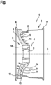
- the figure shows a schematic longitudinal section through a motor vehicle rim 1 for a wheel of a motor vehicle.
- the motor vehicle rim 1 has, as its essential components, a rim well 2, a rim center 3, and a hub 4.
- the motor vehicle rim 1 is shown in longitudinal section with respect to a longitudinal center axis 5 of the motor vehicle rim 1.
- the rim well 2 is bounded in the axial direction on the one hand by an outer flange 6 and on the other hand by an inner flange 7, which extend outwards from the rim well 2 in the radial direction with respect to the longitudinal center axis 5.
- the axial extent of the rim well 2 extends to a respective outer end of the outer flange 6 and the inner flange 7, respectively.
- the axial extent of the rim well 2 therefore includes the axial extents of the outer flange 6 and the inner flange 7.
- the rim well 2 and the hub 4 are connected to each other via the rim center 3.
- the rim center 3 thus engages both the rim well 2 and the hub 4 and extends from the hub 4 to the rim well 2.
- the hub 4 has a central recess 8, which is located centrally on the hub 4 with respect to the longitudinal center axis 5 and extends completely through it in the axial direction.
- the hub 4 has a bolt circle 9 with several bores 10, each of which serves to receive a fastening means by means of which the motor vehicle rim 1 can be or is fastened to a wheel hub of the motor vehicle.
- the rim center 3 has several spokes 11, which are arranged spaced apart from one another in the circumferential direction.
- Each of the spokes 11 extends from the hub 4 to the rim base 2 in the circumferential direction.
- An interspoke element can be formed in this interspoke region, which, for example, completely fills the interspoke region.
- At least the interspoke element 12 has a small wall thickness of at most 5 mm.
- the motor vehicle rim 1 is manufactured in one piece and continuously in a casting mold by die-casting a casting material. Aluminum or an aluminum alloy is used as the casting material.
- the motor vehicle rim 1 In order to ensure good cooling of the motor vehicle rim 1, it has at least one air conveying element 12 (of which only one is shown as an example) and at least one surface enlargement element 13. In the exemplary embodiment shown here, several surface enlargement elements 13 are realized, of which only some are shown as examples.
- the air conveying element 12 serves to convey air in the axial direction with respect to the longitudinal center axis 5.
- the flow direction of the air which is achieved by means of the air conveying element 12 during a rotational movement of the motor vehicle rim 1 about the longitudinal center axis 5, is indicated by way of example by the arrows 14.
- the air conveying element 12 extends from the spoke 11; preferably, each of the spokes 11 is assigned such an air conveying element 12 (not shown).
- the air conveying element 12 is preferably designed with a small wall thickness of at most 15 mm, at most 10 mm, at most 7.5 mm, at most 5 mm, or less. In particular, the air conveying element 12 has a wall thickness of at most 2.5 mm, at most 2 mm, at most 1.5 mm, or at most 1 mm.
- the surface enlargement element 13 extends from the spoke 11 or the spokes 11 in the axial direction toward the inner flange 7. If, as here, several surface enlargement elements 13 are present, they are arranged spaced apart from one another in the radial direction. For example, starting from the rim center 3, they each have the same extension in the axial direction. They can axially offset from one another, for example due to an offset and/or a curvature of the rim center 3.
- the surface enlargement element 13 extends in the circumferential direction along a circular line. Particularly preferably, the surface enlargement element 13 is circular or annular in shape overall. It is thus in the form of a hollow circular cylinder, which is arranged with a first end face at the rim center 3 and has a free end at its second end face.
- the described design of the motor vehicle rim 1 achieves an extremely delicate appearance and, at the same time, ensures cost-effective and rapid production of the motor vehicle rim 1 due to the die-casting process. Furthermore, excellent strength values are achieved by die-casting the aluminum or aluminum alloy, and effective heat dissipation from the motor vehicle rim 1 is ensured due to the air conveying element 12 and/or the surface enlargement element 13.
Landscapes
- Engineering & Computer Science (AREA)
- Mechanical Engineering (AREA)
- Molds, Cores, And Manufacturing Methods Thereof (AREA)
- Arrangement Or Mounting Of Propulsion Units For Vehicles (AREA)
Claims (8)
- Procédé de fabrication d'une jante pour véhicule automobile (1) en aluminium ou en alliage d'aluminium pour une roue d'un véhicule automobile, dans lequel la jante pour véhicule automobile (1) présente une embase de jante (2) délimitée sur des côtés opposés par un cornet extérieur (6) et un cornet intérieur (7), un moyeu (4) avec un évidement central (8) et un cercle de perçage (9) ainsi qu'un centre de jante (3) reliant l'embase de jante (2) et le moyeu (4) l'un à l'autre, caractérisé en ce que la jante pour véhicule automobile (1) est fabriquée d'un seul tenant et en continu dans un moule par coulage par coulée sous pression d'un matériau de coulée, dans lequel, lors de la coulée sous pression, au moins un élément de transport d'air (12) disposé pour transporter de l'air en direction axiale par rapport à un axe central longitudinal (5) de la jante pour véhicule automobile (1) par rapport à un plan imaginaire perpendiculaire à l'axe central longitudinal (5) et/ou au moins un élément d'agrandissement de surface (13) s'étendant en direction circonférentielle le long d'une ligne circulaire est formé sur la jante pour véhicule automobile (1) à partir du centre de jante (3) du côté intérieur de la jante.
- Procédé selon la revendication 1, caractérisé en ce que la jante pour véhicule automobile- présente au moins par endroits une épaisseur de paroi faible d'au plus 15 mm, et/ou- présente une courbure avec un rayon de courbure faible d'au plus 4 mm, et/ou- présente une surface de déformation s'étendant en direction radiale et/ou en direction axiale et en direction tangentielle par rapport à un axe central longitudinal (5) de la jante pour véhicule automobile (1), surface qui se trouve entièrement dans un plan imaginaire, dans lequel le plan forme avec l'axe central longitudinal un angle qui s'élève à plus de 0° et au plus à 4°.
- Procédé selon l'une quelconque des revendications précédentes, caractérisé en ce que le centre de jante (3) est réalisé avec plusieurs rayons (11) espacés les uns des autres en direction circonférentielle par rapport à l'axe central longitudinal (5) de la jante pour véhicule automobile (1).
- Procédé selon l'une quelconque des revendications précédentes, caractérisé en ce que l'élément d'agrandissement de surface (13) est formé à partir de l'élément de transport d'air (12).
- Procédé selon l'une quelconque des revendications précédentes, caractérisé en ce que l'élément de transport d'air (12) est réalisé en s'étendant en direction radiale par rapport à l'axe central longitudinal (5) à partir du moyeu (4) jusqu'à l'embase de jante (2).
- Procédé selon l'une quelconque des revendications précédentes, caractérisé en ce que l'élément de transport d'air (12), vu en section longitudinale, est conçu avec une extension en direction axiale qui correspond au plus à une extension du centre de jante (3) dans la même direction ou est supérieure au plus de 50 % à celle-ci.
- Procédé selon l'une quelconque des revendications précédentes, caractérisé en ce que le moule utilisé pour le coulage sous pression fait partie d'un outil de coulée sous pression et en ce que le matériau de coulée est introduit dans le moule à travers au moins une ouverture d'injection.
- Jante pour véhicule automobile (1) en aluminium ou en alliage d'aluminium pour une roue d'un véhicule automobile, fabriquée selon une ou plusieurs des revendications précédentes, dans lequel la jante pour véhicule automobile (1) présente une embase de jante (2) délimitée sur des côtés opposés par un cornet extérieur (6) et un cornet intérieur (7), un moyeu (4) avec un évidement central (8) et un cercle de perçage (9) ainsi qu'un centre de jante (3) reliant l'embase de jante (2) et le moyeu (4) l'un à l'autre, caractérisé en ce que la jante pour véhicule automobile (1) est fabriquée d'un seul tenant et en continu dans un moule par coulage par coulée sous pression d'un matériau de coulée, dans lequel la jante pour véhicule automobile (1) présente au moins un élément de transport d'air disposé pour transporter de l'air en direction axiale par rapport à un axe central longitudinal (5) de la jante pour véhicule automobile par rapport à un plan imaginaire perpendiculaire à l'axe central longitudinal (5) et/ou au moins un élément d'agrandissement de surface (13) s'étendant en direction circonférentielle le long d'une ligne circulaire qui est formé lors de la coulée sous pression.
Applications Claiming Priority (2)
| Application Number | Priority Date | Filing Date | Title |
|---|---|---|---|
| DE102020100693.4A DE102020100693A1 (de) | 2020-01-14 | 2020-01-14 | Verfahren zum Herstellen einer Kraftwagenfelge aus Aluminium oder einer Aluminiumlegierung für ein Rad eines Kraftfahrzeugs sowie entsprechende Kraftwagenfelge |
| PCT/EP2020/082531 WO2021144052A1 (fr) | 2020-01-14 | 2020-11-18 | Procédé de production d'une jante de véhicule automobile en aluminium ou en alliage d'aluminium pour une roue d'un véhicule automobile et jante de véhicule automobile correspondante |
Publications (2)
| Publication Number | Publication Date |
|---|---|
| EP4090542A1 EP4090542A1 (fr) | 2022-11-23 |
| EP4090542B1 true EP4090542B1 (fr) | 2025-05-28 |
Family
ID=73476173
Family Applications (1)
| Application Number | Title | Priority Date | Filing Date |
|---|---|---|---|
| EP20808404.6A Active EP4090542B1 (fr) | 2020-01-14 | 2020-11-18 | Procédé de production d'une jante de véhicule automobile en aluminium ou en alliage d'aluminium pour une roue d'un véhicule automobile et jante de véhicule automobile correspondante |
Country Status (5)
| Country | Link |
|---|---|
| US (1) | US12466212B2 (fr) |
| EP (1) | EP4090542B1 (fr) |
| CN (1) | CN115003517A (fr) |
| DE (1) | DE102020100693A1 (fr) |
| WO (1) | WO2021144052A1 (fr) |
Citations (2)
| Publication number | Priority date | Publication date | Assignee | Title |
|---|---|---|---|---|
| DE102013002632B4 (de) * | 2012-02-16 | 2015-05-07 | Audi Ag | Aluminium-Silizium-Druckgusslegierung und Verfahren zur Herstellung eines Druckgussbauteils |
| EP3650243A1 (fr) * | 2018-11-09 | 2020-05-13 | FERRARI S.p.A. | Jante de roue de véhicule |
Family Cites Families (21)
| Publication number | Priority date | Publication date | Assignee | Title |
|---|---|---|---|---|
| GB8706113D0 (en) * | 1987-03-14 | 1987-04-15 | Wheel Base Nelson Ltd | Wheel |
| DE3724928A1 (de) | 1987-07-28 | 1989-02-16 | Bayerische Motoren Werke Ag | Herstell-verfahren fuer leichtmetallguss-bauteile, insbesondere leichtmetallguss-raeder fuer personenkraftwagen |
| US5096264A (en) | 1989-08-31 | 1992-03-17 | Masakazu Hayashi | Double disk construction for automobile wheels of light alloy |
| JP2517383Y2 (ja) * | 1990-09-13 | 1996-11-20 | トピー工業株式会社 | 軽合金製鋳造ホイール |
| DE4138558C2 (de) | 1991-11-23 | 1994-05-11 | Porsche Ag | Rad und ein Verfahren zum Herstellen des Rades |
| WO1995009710A1 (fr) * | 1993-10-07 | 1995-04-13 | Hayes Wheels International, Inc. | Procede et appareil pour controler et orienter la solidification de la coulee d'une roue |
| AT409728B (de) * | 2000-03-09 | 2002-10-25 | Austria Alu Guss Ges M B H | Verfahren zum herstellen einer rad-gussfelge und giesswerkzeug hierfür |
| DE10330400A1 (de) | 2003-07-04 | 2005-01-20 | Alutec-Belte Ag | Verfahren und Vorrichtung zum Abschrecken eines Gussteils |
| EP1714798B1 (fr) * | 2004-02-03 | 2012-09-12 | Washi Kosan Co., Ltd. | Roue en alliage leger |
| PL1737681T3 (pl) * | 2004-04-23 | 2008-07-31 | Hayes Lemmerz S R L | Proces wytwarzania felgi ze stopu lekkiego i felga uzyskiwana w takim procesie |
| US20090236902A1 (en) | 2008-03-21 | 2009-09-24 | Mordecai Zibkoff | Spoked Bicycle Wheel |
| RU2517645C2 (ru) * | 2008-11-28 | 2014-05-27 | Сумитомо Раббер Индастриз, Лтд. | Обод колеса шины |
| US20140191564A1 (en) * | 2013-01-07 | 2014-07-10 | Gary Gebeau | Rim, airless tire and hubcap designs configured to directionally convey air and methods for their use |
| DE102013208226B4 (de) * | 2013-05-06 | 2024-01-25 | Robert Bosch Gmbh | Kühlelement für einen Radnabenantrieb sowie Radnabenantrieb |
| TW201444705A (zh) | 2013-05-20 | 2014-12-01 | 雙齊企業有限公司 | 車輛輪圈 |
| EP2848333B1 (fr) * | 2013-09-16 | 2021-03-24 | Mubea Carbo Tech GmbH | Procédé et dispositif de fabrication d'un composant métallique au moyen d'un outil de coulage et de formage |
| US9815323B2 (en) * | 2014-07-24 | 2017-11-14 | Superior Industries International, Inc. | Cast aluminum wheel |
| JP2017001549A (ja) * | 2015-06-11 | 2017-01-05 | 中央精機株式会社 | 自動車用ホイール |
| CN105538997A (zh) * | 2016-01-30 | 2016-05-04 | 太仓丹妮尔模塑汽配有限公司 | 一种具有良好散热功能的汽车轮毂 |
| DE102016106256B3 (de) * | 2016-04-06 | 2017-03-02 | Stefan Argirov | Vorrichtung zur Herstellung von Gussteilen, wie Aluminiumguss, im Niederdruckgießverfahren |
| DE102019102067A1 (de) | 2019-01-28 | 2020-07-30 | Bayerische Motoren Werke Aktiengesellschaft | Verfahren zur Herstellung eines gegossenen Fahrzeugrads |
-
2020
- 2020-01-14 DE DE102020100693.4A patent/DE102020100693A1/de active Pending
- 2020-11-18 US US17/787,735 patent/US12466212B2/en active Active
- 2020-11-18 WO PCT/EP2020/082531 patent/WO2021144052A1/fr not_active Ceased
- 2020-11-18 CN CN202080093149.2A patent/CN115003517A/zh active Pending
- 2020-11-18 EP EP20808404.6A patent/EP4090542B1/fr active Active
Patent Citations (2)
| Publication number | Priority date | Publication date | Assignee | Title |
|---|---|---|---|---|
| DE102013002632B4 (de) * | 2012-02-16 | 2015-05-07 | Audi Ag | Aluminium-Silizium-Druckgusslegierung und Verfahren zur Herstellung eines Druckgussbauteils |
| EP3650243A1 (fr) * | 2018-11-09 | 2020-05-13 | FERRARI S.p.A. | Jante de roue de véhicule |
Also Published As
| Publication number | Publication date |
|---|---|
| WO2021144052A1 (fr) | 2021-07-22 |
| US20230074550A1 (en) | 2023-03-09 |
| US12466212B2 (en) | 2025-11-11 |
| DE102020100693A1 (de) | 2021-07-15 |
| CN115003517A (zh) | 2022-09-02 |
| EP4090542A1 (fr) | 2022-11-23 |
Similar Documents
| Publication | Publication Date | Title |
|---|---|---|
| EP4090541B1 (fr) | Jante pour roue de véhicule, en aluminium ou en alliage d'aluminium | |
| DE112007000192B4 (de) | Verfahren zum Herstellen einer Radschüssel | |
| EP1964690B1 (fr) | Roue en fonte et moule en fonte destiné à la fabrication d'une roue en fonte | |
| DE3217458C2 (de) | Einstückig aus einer Leichtmetallegierung gegossenes oder geschmiedetes Rad für Kraftfahrzeuge, sowie Verfahren zu seiner Herstellung | |
| DE2442785B2 (de) | Verfahren zur herstellung einer einteiligen ringfelge oder eines ringfelgenteils | |
| DE112006000508T5 (de) | Radscheibe für ein zusammengesetztes Kraftfahrzeugrad sowie zusammengesetztes Kraftfahrzeugrad mit einer solchen Radscheibe | |
| EP3956484A1 (fr) | Pièce, procédé et dispositif de trempe d'une pièce | |
| EP4090543A1 (fr) | Procédé de production d'une jante de véhicule automobile en aluminium ou en alliage d'aluminium pour une roue d'un véhicule automobile et dispositif correspondant de production d'une jante de véhicule automobile | |
| DE102020100689A1 (de) | Verfahren zum Herstellen einer Kraftwagenfelge aus Aluminium oder einer Aluminiumlegierung für ein Rad eines Kraftfahrzeugs sowie Kraftwagenfelge | |
| DE102020100704A1 (de) | Verfahren zum Herstellen einer Kraftwagenfelge aus Aluminium oder einer Aluminiumlegierung für ein Rad eines Kraftfahrzeugs sowie Vorrichtung zum Herstellen einer Kraftwagenfelge | |
| EP4058300B1 (fr) | Roue à disque pour véhicule à moteur et procédé de production d'une roue à disque de ce type | |
| DE2824972C2 (de) | Aus zwei miteinander verbundenen Teilen bestehendes Kraftfahrzeugrad | |
| DE10297394T5 (de) | Zusammengesetztes Vollscheibenfahrzeugrad und Verfahren zu dessen Herstellung | |
| EP4090783A1 (fr) | Procédé de production d'une jante de véhicule automobile en alliage d'aluminium pour une roue d'un véhicule automobile et jante de véhicule automobile correspondante | |
| DE102020100693A1 (de) | Verfahren zum Herstellen einer Kraftwagenfelge aus Aluminium oder einer Aluminiumlegierung für ein Rad eines Kraftfahrzeugs sowie entsprechende Kraftwagenfelge | |
| DE19829331A1 (de) | Leichtmetallrad | |
| DE102010020913A1 (de) | Verfahren zum Fügen eines Wellenteils mit einem Nabenteil | |
| DE102020100694B3 (de) | Verfahren zum Herstellen einer Kraftwagenfelge aus Aluminium oder einer Aluminiumlegierung für ein Rad eines Kraftfahrzeugs sowie Gießwerkzeug zur Herstellung einer Kraftwagenfelge | |
| DE102005024345A1 (de) | Fahrzeugrad mit einer gefrästen Ablaufnut | |
| EP4090545A1 (fr) | Procédé de fabrication d'une jante de véhicule à moteur en aluminium ou en un alliage d'aluminium pour une roue de véhicule à moteur et jante de véhicule à moteur correspondante | |
| DE102020100696A1 (de) | Verfahren zum Herstellen einer Kraftwagenfelge aus Aluminium oder einer Aluminiumlegierung für ein Rad eines Kraftfahrzeugs sowie entsprechende Kraftwagenfelge | |
| DE3410308A1 (de) | Fahrzeugrad und verfahren zum herstellen eines fahrzeugrades | |
| DE102020100705A1 (de) | Verfahren zum Herstellen einer Kraftwagenfelge aus Aluminium oder einer Aluminiumlegierung für ein Rad eines Kraftfahrzeugs sowie entsprechende Vorrichtung zum Herstellen einer Kraftwagenfelge | |
| WO1990013444A1 (fr) | Roue de vehicule | |
| EP3365185B1 (fr) | Procédé de fabrication d'une roue, moule de fabrication et roue |
Legal Events
| Date | Code | Title | Description |
|---|---|---|---|
| STAA | Information on the status of an ep patent application or granted ep patent |
Free format text: STATUS: UNKNOWN |
|
| STAA | Information on the status of an ep patent application or granted ep patent |
Free format text: STATUS: THE INTERNATIONAL PUBLICATION HAS BEEN MADE |
|
| PUAI | Public reference made under article 153(3) epc to a published international application that has entered the european phase |
Free format text: ORIGINAL CODE: 0009012 |
|
| STAA | Information on the status of an ep patent application or granted ep patent |
Free format text: STATUS: REQUEST FOR EXAMINATION WAS MADE |
|
| 17P | Request for examination filed |
Effective date: 20220816 |
|
| AK | Designated contracting states |
Kind code of ref document: A1 Designated state(s): AL AT BE BG CH CY CZ DE DK EE ES FI FR GB GR HR HU IE IS IT LI LT LU LV MC MK MT NL NO PL PT RO RS SE SI SK SM TR |
|
| DAV | Request for validation of the european patent (deleted) | ||
| DAX | Request for extension of the european patent (deleted) | ||
| P01 | Opt-out of the competence of the unified patent court (upc) registered |
Effective date: 20230529 |
|
| GRAP | Despatch of communication of intention to grant a patent |
Free format text: ORIGINAL CODE: EPIDOSNIGR1 |
|
| STAA | Information on the status of an ep patent application or granted ep patent |
Free format text: STATUS: GRANT OF PATENT IS INTENDED |
|
| INTG | Intention to grant announced |
Effective date: 20250306 |
|
| GRAS | Grant fee paid |
Free format text: ORIGINAL CODE: EPIDOSNIGR3 |
|
| GRAA | (expected) grant |
Free format text: ORIGINAL CODE: 0009210 |
|
| STAA | Information on the status of an ep patent application or granted ep patent |
Free format text: STATUS: THE PATENT HAS BEEN GRANTED |
|
| AK | Designated contracting states |
Kind code of ref document: B1 Designated state(s): AL AT BE BG CH CY CZ DE DK EE ES FI FR GB GR HR HU IE IS IT LI LT LU LV MC MK MT NL NO PL PT RO RS SE SI SK SM TR |
|
| REG | Reference to a national code |
Ref country code: GB Ref legal event code: FG4D Free format text: NOT ENGLISH |
|
| REG | Reference to a national code |
Ref country code: CH Ref legal event code: EP |
|
| REG | Reference to a national code |
Ref country code: IE Ref legal event code: FG4D Free format text: LANGUAGE OF EP DOCUMENT: GERMAN Ref country code: DE Ref legal event code: R096 Ref document number: 502020011138 Country of ref document: DE |
|
| REG | Reference to a national code |
Ref country code: NL Ref legal event code: MP Effective date: 20250528 |
|
| PG25 | Lapsed in a contracting state [announced via postgrant information from national office to epo] |
Ref country code: ES Free format text: LAPSE BECAUSE OF FAILURE TO SUBMIT A TRANSLATION OF THE DESCRIPTION OR TO PAY THE FEE WITHIN THE PRESCRIBED TIME-LIMIT Effective date: 20250528 Ref country code: FI Free format text: LAPSE BECAUSE OF FAILURE TO SUBMIT A TRANSLATION OF THE DESCRIPTION OR TO PAY THE FEE WITHIN THE PRESCRIBED TIME-LIMIT Effective date: 20250528 |
|
| REG | Reference to a national code |
Ref country code: LT Ref legal event code: MG9D |
|
| PG25 | Lapsed in a contracting state [announced via postgrant information from national office to epo] |
Ref country code: GR Free format text: LAPSE BECAUSE OF FAILURE TO SUBMIT A TRANSLATION OF THE DESCRIPTION OR TO PAY THE FEE WITHIN THE PRESCRIBED TIME-LIMIT Effective date: 20250829 Ref country code: NO Free format text: LAPSE BECAUSE OF FAILURE TO SUBMIT A TRANSLATION OF THE DESCRIPTION OR TO PAY THE FEE WITHIN THE PRESCRIBED TIME-LIMIT Effective date: 20250828 |
|
| PG25 | Lapsed in a contracting state [announced via postgrant information from national office to epo] |
Ref country code: PL Free format text: LAPSE BECAUSE OF FAILURE TO SUBMIT A TRANSLATION OF THE DESCRIPTION OR TO PAY THE FEE WITHIN THE PRESCRIBED TIME-LIMIT Effective date: 20250528 Ref country code: NL Free format text: LAPSE BECAUSE OF FAILURE TO SUBMIT A TRANSLATION OF THE DESCRIPTION OR TO PAY THE FEE WITHIN THE PRESCRIBED TIME-LIMIT Effective date: 20250528 |
|
| PG25 | Lapsed in a contracting state [announced via postgrant information from national office to epo] |
Ref country code: BG Free format text: LAPSE BECAUSE OF FAILURE TO SUBMIT A TRANSLATION OF THE DESCRIPTION OR TO PAY THE FEE WITHIN THE PRESCRIBED TIME-LIMIT Effective date: 20250528 |
|
| PG25 | Lapsed in a contracting state [announced via postgrant information from national office to epo] |
Ref country code: HR Free format text: LAPSE BECAUSE OF FAILURE TO SUBMIT A TRANSLATION OF THE DESCRIPTION OR TO PAY THE FEE WITHIN THE PRESCRIBED TIME-LIMIT Effective date: 20250528 |
|
| PG25 | Lapsed in a contracting state [announced via postgrant information from national office to epo] |
Ref country code: RS Free format text: LAPSE BECAUSE OF FAILURE TO SUBMIT A TRANSLATION OF THE DESCRIPTION OR TO PAY THE FEE WITHIN THE PRESCRIBED TIME-LIMIT Effective date: 20250828 |
|
| PG25 | Lapsed in a contracting state [announced via postgrant information from national office to epo] |
Ref country code: IS Free format text: LAPSE BECAUSE OF FAILURE TO SUBMIT A TRANSLATION OF THE DESCRIPTION OR TO PAY THE FEE WITHIN THE PRESCRIBED TIME-LIMIT Effective date: 20250928 |
|
| PG25 | Lapsed in a contracting state [announced via postgrant information from national office to epo] |
Ref country code: LV Free format text: LAPSE BECAUSE OF FAILURE TO SUBMIT A TRANSLATION OF THE DESCRIPTION OR TO PAY THE FEE WITHIN THE PRESCRIBED TIME-LIMIT Effective date: 20250528 |
|
| PGFP | Annual fee paid to national office [announced via postgrant information from national office to epo] |
Ref country code: DE Payment date: 20251130 Year of fee payment: 6 |
|
| PGFP | Annual fee paid to national office [announced via postgrant information from national office to epo] |
Ref country code: GB Payment date: 20251120 Year of fee payment: 6 |
|
| PG25 | Lapsed in a contracting state [announced via postgrant information from national office to epo] |
Ref country code: DK Free format text: LAPSE BECAUSE OF FAILURE TO SUBMIT A TRANSLATION OF THE DESCRIPTION OR TO PAY THE FEE WITHIN THE PRESCRIBED TIME-LIMIT Effective date: 20250528 Ref country code: SM Free format text: LAPSE BECAUSE OF FAILURE TO SUBMIT A TRANSLATION OF THE DESCRIPTION OR TO PAY THE FEE WITHIN THE PRESCRIBED TIME-LIMIT Effective date: 20250528 |
|
| PGFP | Annual fee paid to national office [announced via postgrant information from national office to epo] |
Ref country code: FR Payment date: 20251125 Year of fee payment: 6 |
|
| PG25 | Lapsed in a contracting state [announced via postgrant information from national office to epo] |
Ref country code: CZ Free format text: LAPSE BECAUSE OF FAILURE TO SUBMIT A TRANSLATION OF THE DESCRIPTION OR TO PAY THE FEE WITHIN THE PRESCRIBED TIME-LIMIT Effective date: 20250528 |
|
| PG25 | Lapsed in a contracting state [announced via postgrant information from national office to epo] |
Ref country code: EE Free format text: LAPSE BECAUSE OF FAILURE TO SUBMIT A TRANSLATION OF THE DESCRIPTION OR TO PAY THE FEE WITHIN THE PRESCRIBED TIME-LIMIT Effective date: 20250528 |
|
| PG25 | Lapsed in a contracting state [announced via postgrant information from national office to epo] |
Ref country code: SK Free format text: LAPSE BECAUSE OF FAILURE TO SUBMIT A TRANSLATION OF THE DESCRIPTION OR TO PAY THE FEE WITHIN THE PRESCRIBED TIME-LIMIT Effective date: 20250528 |
|
| PG25 | Lapsed in a contracting state [announced via postgrant information from national office to epo] |
Ref country code: IT Free format text: LAPSE BECAUSE OF FAILURE TO SUBMIT A TRANSLATION OF THE DESCRIPTION OR TO PAY THE FEE WITHIN THE PRESCRIBED TIME-LIMIT Effective date: 20250528 |
|
| REG | Reference to a national code |
Ref country code: DE Ref legal event code: R097 Ref document number: 502020011138 Country of ref document: DE |
|
| PG25 | Lapsed in a contracting state [announced via postgrant information from national office to epo] |
Ref country code: RO Free format text: LAPSE BECAUSE OF FAILURE TO SUBMIT A TRANSLATION OF THE DESCRIPTION OR TO PAY THE FEE WITHIN THE PRESCRIBED TIME-LIMIT Effective date: 20250528 |
|
| PLBE | No opposition filed within time limit |
Free format text: ORIGINAL CODE: 0009261 |
|
| STAA | Information on the status of an ep patent application or granted ep patent |
Free format text: STATUS: NO OPPOSITION FILED WITHIN TIME LIMIT |
|
| REG | Reference to a national code |
Ref country code: CH Ref legal event code: L10 Free format text: ST27 STATUS EVENT CODE: U-0-0-L10-L00 (AS PROVIDED BY THE NATIONAL OFFICE) Effective date: 20260409 |
|
| 26N | No opposition filed |
Effective date: 20260303 |