EP4090604B1 - Verpackung mit verbessertem verschluss - Google Patents
Verpackung mit verbessertem verschluss Download PDFInfo
- Publication number
- EP4090604B1 EP4090604B1 EP21702342.3A EP21702342A EP4090604B1 EP 4090604 B1 EP4090604 B1 EP 4090604B1 EP 21702342 A EP21702342 A EP 21702342A EP 4090604 B1 EP4090604 B1 EP 4090604B1
- Authority
- EP
- European Patent Office
- Prior art keywords
- closure
- frangible connection
- container
- tab
- package
- Prior art date
- Legal status (The legal status is an assumption and is not a legal conclusion. Google has not performed a legal analysis and makes no representation as to the accuracy of the status listed.)
- Active
Links
Images



Classifications
-
- B—PERFORMING OPERATIONS; TRANSPORTING
- B65—CONVEYING; PACKING; STORING; HANDLING THIN OR FILAMENTARY MATERIAL
- B65D—CONTAINERS FOR STORAGE OR TRANSPORT OF ARTICLES OR MATERIALS, e.g. BAGS, BARRELS, BOTTLES, BOXES, CANS, CARTONS, CRATES, DRUMS, JARS, TANKS, HOPPERS, FORWARDING CONTAINERS; ACCESSORIES, CLOSURES, OR FITTINGS THEREFOR; PACKAGING ELEMENTS; PACKAGES
- B65D55/00—Accessories for container closures not otherwise provided for
- B65D55/16—Devices preventing loss of removable closure members
-
- B—PERFORMING OPERATIONS; TRANSPORTING
- B65—CONVEYING; PACKING; STORING; HANDLING THIN OR FILAMENTARY MATERIAL
- B65D—CONTAINERS FOR STORAGE OR TRANSPORT OF ARTICLES OR MATERIALS, e.g. BAGS, BARRELS, BOTTLES, BOXES, CANS, CARTONS, CRATES, DRUMS, JARS, TANKS, HOPPERS, FORWARDING CONTAINERS; ACCESSORIES, CLOSURES, OR FITTINGS THEREFOR; PACKAGING ELEMENTS; PACKAGES
- B65D41/00—Caps, e.g. crown caps or crown seals, i.e. members having parts arranged for engagement with the external periphery of a neck or wall defining a pouring opening or discharge aperture; Protective cap-like covers for closure members, e.g. decorative covers of metal foil or paper
- B65D41/32—Caps or cap-like covers with lines of weakness, tearing-strips, tags, or like opening or removal devices, e.g. to facilitate formation of pouring openings
- B65D41/34—Threaded or like caps or cap-like covers provided with tamper elements formed in, or attached to, the closure skirt
- B65D41/3423—Threaded or like caps or cap-like covers provided with tamper elements formed in, or attached to, the closure skirt with flexible tabs, or elements rotated from a non-engaging to an engaging position, formed on the tamper element or in the closure skirt
- B65D41/3428—Threaded or like caps or cap-like covers provided with tamper elements formed in, or attached to, the closure skirt with flexible tabs, or elements rotated from a non-engaging to an engaging position, formed on the tamper element or in the closure skirt the tamper element being integrally connected to the closure by means of bridges
-
- B—PERFORMING OPERATIONS; TRANSPORTING
- B65—CONVEYING; PACKING; STORING; HANDLING THIN OR FILAMENTARY MATERIAL
- B65D—CONTAINERS FOR STORAGE OR TRANSPORT OF ARTICLES OR MATERIALS, e.g. BAGS, BARRELS, BOTTLES, BOXES, CANS, CARTONS, CRATES, DRUMS, JARS, TANKS, HOPPERS, FORWARDING CONTAINERS; ACCESSORIES, CLOSURES, OR FITTINGS THEREFOR; PACKAGING ELEMENTS; PACKAGES
- B65D43/00—Lids or covers for rigid or semi-rigid containers
- B65D43/14—Non-removable lids or covers
- B65D43/16—Non-removable lids or covers hinged for upward or downward movement
- B65D43/163—Non-removable lids or covers hinged for upward or downward movement the container and the lid being made separately
-
- B—PERFORMING OPERATIONS; TRANSPORTING
- B65—CONVEYING; PACKING; STORING; HANDLING THIN OR FILAMENTARY MATERIAL
- B65D—CONTAINERS FOR STORAGE OR TRANSPORT OF ARTICLES OR MATERIALS, e.g. BAGS, BARRELS, BOTTLES, BOXES, CANS, CARTONS, CRATES, DRUMS, JARS, TANKS, HOPPERS, FORWARDING CONTAINERS; ACCESSORIES, CLOSURES, OR FITTINGS THEREFOR; PACKAGING ELEMENTS; PACKAGES
- B65D2251/00—Details relating to container closures
- B65D2251/10—Details of hinged closures
- B65D2251/1008—Means for locking the closure in open position
-
- B—PERFORMING OPERATIONS; TRANSPORTING
- B65—CONVEYING; PACKING; STORING; HANDLING THIN OR FILAMENTARY MATERIAL
- B65D—CONTAINERS FOR STORAGE OR TRANSPORT OF ARTICLES OR MATERIALS, e.g. BAGS, BARRELS, BOTTLES, BOXES, CANS, CARTONS, CRATES, DRUMS, JARS, TANKS, HOPPERS, FORWARDING CONTAINERS; ACCESSORIES, CLOSURES, OR FITTINGS THEREFOR; PACKAGING ELEMENTS; PACKAGES
- B65D2401/00—Tamper-indicating means
- B65D2401/15—Tearable part of the closure
-
- B—PERFORMING OPERATIONS; TRANSPORTING
- B65—CONVEYING; PACKING; STORING; HANDLING THIN OR FILAMENTARY MATERIAL
- B65D—CONTAINERS FOR STORAGE OR TRANSPORT OF ARTICLES OR MATERIALS, e.g. BAGS, BARRELS, BOTTLES, BOXES, CANS, CARTONS, CRATES, DRUMS, JARS, TANKS, HOPPERS, FORWARDING CONTAINERS; ACCESSORIES, CLOSURES, OR FITTINGS THEREFOR; PACKAGING ELEMENTS; PACKAGES
- B65D2401/00—Tamper-indicating means
- B65D2401/15—Tearable part of the closure
- B65D2401/30—Tamper-ring remaining connected to closure after initial removal
Definitions
- the present invention relates generally to a package with a tethered closure. More specifically, the present invention relates to a package with a tethered polymeric closure that is maintained in a locked position after opening.
- Polymeric closures have been used in many applications over the years in conjunction with containers.
- One type of polymeric closure that has been used with containers is a tamper-evident polymeric closure. Tamper-evident closures are used to prevent or inhibit tampering by providing a visible indication to a user if the closure has been opened. This visual indication typically divides the closure into two separate components after the tamper-evident feature has been broken. The top portion of the closure is then removed from the container to gain access to the contents of the containers.
- One drawback of tamper-evident closures being separated into two individual components is that the top portion may not be recycled along with the remainder of the closure and container. This scenario raises potential environmental concerns with so many containers having tamper-evident features on its closures that can be separated into two individual components.
- FIG. 1 One non-limiting example of the same is shown in PRIOR ART FIG. 1 in which a package 310 includes a container or finish 320 and a closure 330.
- the package 310 of FIG. 1 is shown in an open position in which the closure 330 is in a locked position with respect to the container 320.
- the closure to finish orientation is not desired (angle A) in that a large area 340 of the closure 330 is located above the drinking surface.
- the large area 340 is the portion of the closure 330 that is located above line A in
- the angle A of the package 310 will produce various flip angles based on where the closure 330 is oriented on the container 320. More specifically, the closure flip angle ranges depending on the radial location of the closure relative to the container when flipped. For example, since the closure locking tab comes to rest against the bottom side of the container thread in FIG. 1 , the minimum flip angle occurs when the locking tab radially aligns at an end of the external thread formation of the container. Examples of such packages comprising a container and a tethered closure are disclosed in documents WO2019/031779A1 and EP2308772A1 .
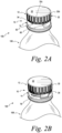
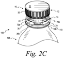
- FIGS. 2A-C illustrate a package 100 including a polymeric twist and flip closure 10 and a container 108 according to one embodiment of the present invention.
- the twist and flip closures are configured to be placed on a container or bottle that contain product.
- the product is typically a liquid product, but also may be a solid product or a combination of a liquid and solid product.
- the polymeric closure 10 of FIGS. 2A-C is generally cylindrically shaped.
- the closure is configured to remain with the container so as to reduce environmental waste, while still providing desirable tamper-evident features.
- the closure is configured to lock after opening so as to enjoy an uninhibited drinking experience.
- the polymeric closure 10 includes a first closure portion or lid 12 and a second closure portion or base 14.
- the closure 10 is a one-piece closure.
- the first closure portion 12 and the second closure portion 14 are adapted to be twisted and then flipped with respect to each other via a tab as will be discussed in detail below. It is contemplated that the closure may be a two-piece closure in another embodiment.
- the first closure portion 12 includes a polymeric top wall portion 22 and a polymeric annular skirt portion 32.
- the second closure portion 14 includes a polymeric tamper-evident band 34.
- the polymeric tamper-evident band 34 depends from and is partially detachably connected to the polymeric annular skirt portion 32 by a first frangible connection 50 ( FIG. 2A ).
- the first closure portion 12 further includes a polymeric continuous plug seal 24 and an outer seal 26.
- the polymeric continuous plug seal 24 and the outer seal 26 depend from the polymeric top wall portion 22 and provide a sealing mechanism.
- the continuous plug seal 24 of FIG. 4 is spaced from an interior surface 32a of the polymeric annular skirt portion 32.
- the outer seal 26 provides an outer seal with respect to an outer finish surface of the container 108.
- the closure may include other sealing mechanisms.
- the closure may include a polymeric lining material that provides a seal to the closure.
- the closure would be formed from separate components, but would function as the closure except with a different sealing mechanism.
- the closure may include only a polymeric outer seal or a continuous plug seal. It is contemplated that the closure may include other sealing mechanisms.
- the polymeric annular skirt portion 32 includes an internal thread formation 40 for mating engagement with an external thread formation of a container.
- the internal thread formation 40 includes a first closure lead 42 and a second closure lead 44.
- the first and second closure leads 42, 44 are referred collectively as a double lead closure thread.
- Each of the first and second closure leads 42, 44 is continuous.
- the first positions of the first and second closure leads 42, 44 may be located roughly 180 degrees apart from each other and, thus, begin on generally opposing sides of the closure 10.
- first and second closure leads may be discontinuous. It is also contemplated that the internal thread formation of the closure may differ from a helical thread formation. It is also contemplated that other internal thread formations may be used in the closure. For example, the internal thread formation may include a triple-threaded structure having first, second and third closure leads.
- an outer surface 32b of the polymeric annular skirt portion 32 may also include a plurality of ridges 32c thereon.
- the plurality of ridges 32c assists a user in gripping when moving the closure 10 between closed and open positions.
- FIG. 2A depicts the closure 10 and the container 108 in an unopened position.
- FIG. 2B depicts the closure 10 and the container 108 in a partially open position.
- FIG. 2C depicts the closure 10 and the container 108 in an open, but not flipped, position. It is noted that FIG. 2C is a top perspective view of the front, while FIGS. 2A and 2B are slightly offset as compared to the view of FIG. 2C .
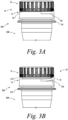
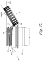
- FIGS. 3A-3C the closure 10 is shown with a container 208 from a side perspective view that forms a package 200.
- the closure 10 of FIG. 3A includes the first and second frangible connections 50 and 60.
- FIG. 3A depicts the closure 10 and the container 208 in an unopened position.
- FIG. 3B depicts the closure 10 and the container 208 in an open, but not flipped, position.
- FIG. 3C depicts the closure 10 and the container 208 in the flipped and locked position.
- FIG. 5 depicts the entire circumference of the closure 10 in a flatten side view in an unopened position.
- the first frangible connection 50 extends around the circumference of the closure 10.
- the first frangible connection generally extends from about 280 to about 330 degrees around the circumference of the closure 10. More specifically, the first frangible connection extends from about 300 to about 325 degrees or, more specifically, from about 310 to about 320 degrees around the circumference of the closure 10.
- the first frangible connection 50 has a first end 50a and a second end 50b.
- the first and second ends 50a, 50b are spaced apart. This is shown in FIG. 5 as a gap 52.
- the gap 52 is generally from about 30 to about 80 degrees and, more specifically, from about 40 to about 60 degrees around the circumference of the closure.
- the second frangible connection 60 has a first section 62 and a second section 64. As shown in FIG. 5 , the second frangible connection 60 extends generally from about 120 to about 180 degrees around the circumference of the closure 10. More specifically, the second frangible connection extends from about 130 to about 170 degrees around the circumference of the closure 10.
- the first section 62 has a plurality of segments 62a, 62b.
- the second frangible connection 60 has a configuration that includes the first section 62 and the second section 64.
- the first section 62 has two segments 62a, 62b and the second section 64 has three segments 64a-c.
- the first section 62 and the second section 64 are connected as shown in FIG. 5 .
- the two segments 62a, 62b are generally horizontal.
- the segments are 64a, 64c are generally vertical, while the segment 64b is generally horizontal.
- the segments 64a-c are connected with each other and form an area 66.
- the segments 64a-c form a general U-shape.
- the second section of the second frangible connection may be of shapes other than U-shaped.
- the second section of the second frangible connection may be an elongated oval section or a W-shape.
- the second frangible connection 60 is spaced from the first frangible connection 50. At least a portion of the second frangible connection is located further from the top wall portion than a portion of the first frangible connection. In FIG. 5 , the entire second frangible connection 60 is located further from the top wall portion 22 than the first frangible connection 50. It is contemplated that the second frangible connection may be formed differently than depicted in FIG. 5 .
- the first and second frangible connections 50, 60 may be formed by molded-in-bridges in one embodiment.
- the molded-in-bridges are formed using a feature in the mold.
- the first and second frangible connections are in the form of scoring or scored lines, notches, leaders, nicks or other lines of weaknesses.
- first and second frangible connections are formed by a slitting technology that is independent from the formation of the remainder of the closure.
- the first and second frangible connections are formed using scoring or scored lines, notches, leaders, nicks or other lines of weaknesses.
- the area 66 is formed between the first section 62 and the second section 64 of the second frangible connection 60 as shown in FIG. 5 .
- the area 66 is adapted to form a tab 70 after the closure has been fully twisted (i.e., fully unthreaded) as shown, for example, in FIG. 2C .
- the tab 70 is located between the first and second ends 50a, 50b as shown in FIG. 5 .
- the area that forms a tab is generally aligned with a gap formed between first and second ends of a first frangible connection.
- the area 66 is substantially aligned with the gap 52 formed between the first and second ends 50a, 50b of the first frangible connection 50. It is contemplated that the area to form the tab should be located in such a manner that the tab acts as a hinge when the closure is flipped and then acts as a lock when the closure has been flipped.
- Areas 68a, 68b are formed between the first frangible connection 50 and the second frangible connection 60 as shown in FIG. 5 .
- the areas 68a, 68b form hinged arms 72a, 72b after the first and second frangible connections are broken.
- the hinged arms 72a, 72b (see, e.g., FIG. 2C ) assist in: (1) keeping the first closure portion 12 and the second closure portion 14 together; (2) flipping the first closure portion 12 with respect to the second closure portion 14 in conjunction with the tab 70; and (3) locking the first closure portion 12 with the tab 70.
- the hinged arms 72a, 72b are sized and shaped to be twisted and stretched.
- the stretching of the hinged arms 72a, 72b is shown, for example, in FIG. 2C by a gap 76 created from the movement of the tab 70.
- the gap 76 of FIG. 2C is larger than a gap 78 shown in FIG. 2B .
- the growth of this gap assists in providing a spatial relationship for providing clearance to flip the first closure portion 12 with respect to the second closure portion 14.
- the spatial relationship for clearance of the first closure portion 12 with respect to the second closure portion 14 is also dependent on other features such as the length of the annular skirt portion 32, the positioning and type of internal and external threads, and the size and shape of the tab 70.
- the polymeric tamper-evident band 34 of the closure 10 is located at the bottom thereof (i.e., an end opposite of the polymeric top wall portion 22).
- the tamper-evident band 34 depends from and is at least partially detachably connected to the annular skirt portion 32 by the first frangible connection 50.
- the polymeric tamper-evident band 34 is a lower tamper-evident feature.
- the tamper-evident band 34 works in conjunction with the container to indicate to a user that the contents of the container may have been accessed.
- the tamper-evident band 34 is designed to partially separate from the annular skirt portion 32 when a user opens the package by twisting the first closure portion 12 with respect to the second closure portion 14. This twisting unthreads the closure 10 with respect to the container 108.
- the tamper-evident band includes at least one band extension.
- the closure 10 is shown in FIG. 6 depicts the tamper-evident band 34 including a plurality of band extensions 36a-c.
- the plurality of band extensions 36a-c assists in positioning the first closure portion or lid 12 in a locked position after the flipping process.
- FIGS. 2A-2C and 4 depict the closure 10 and the container 108 forming the package 100.
- a portion of the container 108 is shown in FIGS. 2A-C and 4 , and includes a neck portion 102 ( FIG. 4 ) that defines an opening.
- the neck portion 102 of the container 108 includes an external thread formation 104, an A-collar 106 ( FIG. 2C ), a continuous outer ring 110 and a continuous bead 112.
- the A-collar 106 prevents or inhibits a tamper-evident band 34 from being removed after the first and second frangible connections 50, 60 are broken.
- the continuous outer ring 110 assists in positioning the tamper-evident band 34.
- the continuous bead 112 functions in the same manner as continuous bead 212, which is discussed in detail below.
- the external thread formation 104 includes a first finish lead 142 and a second finish lead 144.
- the external thread formation 104 (finish leads 142, 144) engages with the corresponding internal thread formation 40 (closure leads 42, 44) ( FIG. 4 ) to seal the package 100.
- the first finish lead 142, 144 may extend in a helical fashion. Each of the first and second finish leads 142, 144 is discontinuous.
- first positions of the first and second finish leads are located roughly 180 degrees apart from each other and, thus, begin on opposing sides of the neck portion of the container.
- a first closure lead is desirably in contact with the first finish lead and the second closure lead is desirably in contact with the second finish lead.
- the external thread formation of the container may have discontinuous leads.
- the external thread formation of the container may be different. Another non-limiting example is depicted in FIG. 3C with the container 208 having a continuous helical external thread formation 204.
- the container 208 includes a neck portion 202, the helical external thread formation 204, a circumferential bead 212, a continuous outer ring 210 and A-collar (not shown).
- the A-collar prevents or inhibits the tamper-evident band 34 from being removed after the first and second frangible connections 50, 60 are broken.
- the continuous outer ring 210 assists in positioning the tamper-evident band 34.
- the external thread formation 204 and the circumferential bead 212 assist in maximizing the flip angle (angle B) of the tethered closure 10. By maximizing the flip angle of the closure 10, this minimizes the likelihood of undesirable contact with a consumer's face during use.
- the increase in the flip angle (angle B in FIG. 3C ) is assisted by removing a portion of the external thread formation 204.
- the portion of the external thread formation that is removed can vary, but is typically from about 40 to about 150 degrees and generally from about 80 to about 130 degrees. The portion of the external thread formation removed would be that located closest to the continuous outer ring 210.
- the circumferential bead 212 enables a greater and more consistent flip angle since the tab 70 locks against the circumferential bead 212 as opposed to against the bottom of the helical path created by the external thread formation 204 of the container 208.
- the flip angle will be consistent because the circumferential bead 212 extends around the circumference of the closure so that this will not change regardless of the radial location of the closure 10 relative to the container 208 when flipped.
- the circumferential bead 212 extends continuously around the circumference of the closure 10. It is contemplated, however, that the circumferential bead may be formed in a discontinuous manner around the circumference of the closure. In such an embodiment, it would be desirable to have the discontinuous portions be of a smaller size than the tab 70.
- the container 208 includes the circumferential bead 212 is formed with a step 212a.
- the step 212a is a portion of the circumferential bead 212 that extends slightly from the remainder of the closure as shown best in FIG. 7B .
- the step 212a facilitates an audible indication of a full closure flip angle.
- the container 208 is shown without the closure 10.
- the container 208 in FIG. 8 shows a depth D1 of the circumferential bead 212 and a depth D2 of the external thread formation 204.
- the depth D1 of the circumferential bead 212 is smaller than the depth D2 of the external thread formation 204.
- the depth D1 of the circumferential bead 212 is generally from about 0.2 to about 0.6 mm and, more specifically, from about 0.3 to about 0.05 or about 0.6 mm.
- the depth D2 of the external thread formation 204 is generally from about 1.2 to about 2.0 mm and, more specifically, from about 1.4 to about 1.8 mm.
- the ratio of the depth D2 of the external thread formation to the depth D1 of the circumferential bead is generally from about 2 to about 8 and, more specifically, from about 2 to about 6, and even, more specifically, from about 3 to about 5.
- the container can be manufactured more economically. This is typically the case since the material used for forming the circumferential bead is less than the material removed from a typical external thread formation.
- the closures may include an oxygen-scavenger material.
- This oxygen-scavenger material may be distributed within the closure or may be a separate layer.
- the oxygen-scavenger material may be any material that assists in removing oxygen within the container, while having little or no effect on the contents within the container.
- the closures may include an oxygen-barrier material.
- the oxygen-barrier material may be added as a separate layer or may be integrated within the closure itself.
- the oxygen-barrier materials assist in preventing or inhibiting oxygen from entering the container through the closure. These materials may include, but are not limited to, ethylene vinyl alcohol (EVOH). It is contemplated that other oxygen-barrier materials may be used in the closure.
- EVOH ethylene vinyl alcohol
- the top wall portion 22 and the annular skirt portion 32 are made of polymeric material.
- the top wall portion 22 and the annular skirt portion 32 are typically made of an olefin (e.g., polyethylene (PE), polypropylene (PP)), polyethylene terephthalate (PET) or blends thereof.
- PE polyethylene
- PP polypropylene
- PET polyethylene terephthalate
- One example of a polyethylene that may be used is high density polyethylene (HDPE). It is contemplated that the top wall portion and the annular skirt portion may be made of other polymeric materials.
- the tamper-evident band 34 is typically made of the same materials as the top wall portion 22 and the annular skirt portion 32.
- the closures are typically formed by processes such as injection or compression molding, extrusion or the combination thereof.
- the containers 108, 208 are typically made of polymeric material.
- a material to be used in forming a polymeric container is polyethylene terephthalate (PET), polypropylene (PP) or blends using the same. It is contemplated that the container may be formed of other polymeric or copolymer materials. It is also contemplated that the container may be formed of glass.
- the containers 108, 208 are typically have an encapsulated oxygen-barrier layer or oxygen barrier material incorporated therein.
- FIGS. 2A-2C and FIGS. 3A-3C methods of opening the twist and flip closure are shown.
- FIGS. 2A and 3A depict the first and second frangible connections 50, 60 in an unopened position after the closure 10 has been applied onto the container 108 or 208.
- a user than twists the closure 10 generally along the first and second frangible connections 50, 60, which begins breaking the first and second frangible connections 50, 60.
- the user will continue twisting the closure until there are no more thread engagements between the closure and the container and the first and second frangible connections have been fully broken.
- FIGS. 2C and 3B depict the closure 10 and respective containers 108, 208 after the twisting has been completed (i.e., unthreaded completely).
- first closure portion 12 flips the first closure portion 12 with respect to the second closure portion 14.
- the first closure portion 12 and the second closure portion 14 are flipped using the tab 70, which acts as a hinge after the first and second frangible connections 50, 60 have been fully broken.
- the tab 70 is shown in FIGS. 2C and 3C .
- the hinged arms 72a, 72b during the flipping process are twisted and stretched as the tab 70 is moved.
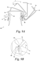
- FIG. 9A shows a side cross-sectional view (without cross-hatching) of the closure 10 and the container 208 in various positions or stages during the flipping process.
- the initial position of the first closure portion or lid 12 is designated as 12a in FIG. 9A .
- the lid moves to a second position (designated as 12b), a third position (designated as 12c), to a fourth position (designated as 12d), to a fifth position (designated as 12e) and to a sixth position (designated as12f).
- the first closure portion or lid 12 is adapted to flip or rotate to an angle B shown in FIG. 3C .
- the first closure portion 12 is adapted to flip or rotate at least 145 degrees from a closed position to an open position until being locked generally along the arrow A of FIG. 9a . It is desirable for the first closure portion or lid 12 to flip or rotate at least about 150 degrees or even more desirably at least 160 degrees from a closed position to an open position until being locked. It is desirable for the first closure portion or lid 12 to flip or rotate at least about 165 degrees or even more desirably at least 170 degrees from a closed position to an open position until being locked.
- the first closure portion or lid 12 generally rotates to an angle B shown in FIG. 3C of about 145 degrees to about 170 degrees and, more specifically, from about 145 degrees to about 165 degrees.
- the first closure portion or lid 12 generally rotates at an angle B shown in FIG. 3C from about 150 degrees to about 170 degrees and, more specifically, from about 150 degrees to about 165 degrees.
- the first closure portion or lid 12 generally rotates at an angle B shown in FIG. 3C from about 155 degrees to about 170 degrees and, more specifically, from about 155 degrees to about 165 degrees.
- FIG. 9B shows an enlarged view of area 9b taken from FIG. 9A.
- FIG. 9B depicts a portion of the first closure portion or lid 12 in the third position 12c and shows the functionality of the band extension 36b with respect to the A-collar 206 of the container 208.
- the tamper-evident feature 34 engages the A-collar 206 to prevent or inhibit the tamper-evident band 34 from being removed after the first and second frangible connections 50, 60 are broken.
- the band extension 36b prevents or inhibits the tab 70 from slipping under the A-collar 206 of the container 208 during movement from the third position (designated as 12c) to the fourth position (designated as 12d) of FIG. 9A . More specifically, during the flipping of the first closure portion 12 during the product opening, the band extension 36b provides a transition lip over the A-collar 206 of the container 208 preventing or inhibiting the tab 70 from slipping under the A-collar 206 and becoming stuck, which prevents or inhibits full rotation of the first closure portion 12. The forces in rotation along arrow B (see FIG. 9B ) allow the tab 70 to slip over the A-collar 206 across the band extension 36b.
- the hinged arms 72a, 72b are twisted and stretched.
- the tab 70 contacts an outer surface of the neck portion 202.
- the tab 70 is generally perpendicular to the outer surface of the neck portion 202, which causes the hinged arms 72a, 72b to be greatly stretched.
- the force required to move the tab to this position is greater than during initial movement of the tab during the flipping process.
- an edge 70a of the tab 70 continues moving upwardly (toward the top of the neck portion 102).
- the tab 70 is sized, and formed to be resilient, but capable of flexing during this movement. At this point, the hinged arms 72a, 72b are not as stretched and are in stable positions.
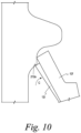
- FIG. 10 an enlarged view of the sixth position 12f of the closure 12 of FIG. 9A is shown.
- the closure 12 In moving from the fifth position 12e of the closure (see FIG. 9A ), the closure 12 contacts the step 212a at a position designated as 12i in FIG. 10 .
- the closure 12 moves between the position 12i and the sixth position 12f generally along arrow C in FIG. 10 , an audible noise occurs to the user that indicates a full closure flip angle.
- the tab 70 in conjunction with the hinged arms 72a, 72b lock the first closure portion 12 with respect to the second closure portion 14 as shown in FIG. 3C .
- the hinged arms 72a, 72b are stable and maintain the tab in a locked position.
- the first closure portion 12 would need some force applied to cause the hinged arms 72, 72b to be returned to this greatly stretched position.
- the closure 10 is adapted to be returned to its initial position by flipping back the first closure portion 12 and then threaded the closure 10 onto the container 208.
- the polymeric closures are desirable in both low-temperature and high-temperature applications.
- the polymeric closures may be used in low-temperature applications such as an ambient or a cold fill. These applications include water, sports drinks, aseptic applications such as dairy products, and pressurized products such as carbonated soft drinks. It is contemplated that other low-temperature applications may be used with the polymeric closures.
- the polymeric closures may be exposed to high-temperature applications such as hot-fill, pasteurization, and retort applications.
- a hot fill application is generally performed at temperatures around 85°C (185°F)
- a hot-fill with pasteurization is generally performed at temperatures around 96°C (205°F).
- Retort applications are typically done at temperatures greater than 121°C (250°F). It is contemplated that the polymeric closures can be used in other high-temperature applications.
Landscapes
- Engineering & Computer Science (AREA)
- Mechanical Engineering (AREA)
- Closures For Containers (AREA)
- Containers Having Bodies Formed In One Piece (AREA)
- Pharmaceuticals Containing Other Organic And Inorganic Compounds (AREA)
- Package Frames And Binding Bands (AREA)
Claims (10)
- Verpackung (100), umfassend:einen Behälter (108, 208) mit einem Halsabschnitt (102, 202), der eine Öffnung definiert, wobei der Behälter (108, 208) eine Außengewindeausbildung (104, 204) auf dem Halsabschnitt (102, 202), einen umlaufenden Wulst (112, 212), einen A-Kragen (106, 206) und einen fortlaufenden Außenring (110, 210) aufweist, wobei der umlaufende Wulst (112, 212) weiter von der Öffnung als die Außengewindeausbildung (104, 204) entfernt ist; undeinen Verschluss (10), der dazu ausgelegt ist, zum Verschließen der Öffnung an dem Halsabschnitt (102, 202) des Behälters (108, 208) angebracht zu werden, wobei der Verschluss (10) einen ersten Verschlussabschnitt (12) und einen zweiten Verschlussabschnitt (14) umfasst, der erste Verschlussabschnitt (12) einen polymeren oberen Wandabschnitt (22), einen polymeren ringförmigen Schürzenabschnitt (32), eine erste zerbrechbare Verbindung (50) und eine zweite zerbrechbare Verbindung (60) umfasst, der polymere ringförmige Schürzenabschnitt (32) von dem polymeren oberen Wandabschnitt (22) abhängt, der ringförmige Schürzenabschnitt (32) eine Innengewindeausbildung (40) für einen zusammenpassenden Eingriff mit der Außengewindeausbildung (104, 204) des Behälters (108, 208) aufweist, der zweite Verschlussabschnitt (14) ein polymeres Originalitätssicherungsband (34) aufweist, das von dem polymeren ringförmigen Schürzenabschnitt (32) abhängt und durch die erste zerbrechbare Verbindung (50) teilweise lösbar mit diesem verbunden ist,wobei der Verschluss (10) dazu angepasst ist, durch Verdrehen geöffnet zu werden, um die erste und die zweite zerbrechbare Verbindung (50, 60) zu brechen und eine Lasche (70) freizulegen, und dann den ersten Verschlussabschnitt (12) über die freigelegte Lasche (70) vom zweiten Verschlussabschnitt (14) abzuklappen,wobei der fortlaufende Außenring (110, 210) bei der Positionierung des Originalitätssicherungsbandes (34) unterstützt, das in den A-Kragen (106, 206) eingreift, um zu verhindern oder zu unterbinden, dass das Originalitätssicherungsband (34) entfernt wird, nachdem die erste und die zweite zerbrechbare Verbindung (50, 60) gebrochen sind,dadurch gekennzeichnet, dass sich der umlaufende Wulst (112, 212) um den Umfang des Verschlusses (10) erstreckt;wobei der Verschluss dazu angepasst ist, während des Umklappens des ersten Verschlussabschnitts (12) vom zweiten Verschlussabschnitt (14) über die Lasche (70) gegen den umlaufenden Wulst (112, 212) verriegelt zu werden,wobei die Lasche (70) als Scharnier wirkt, wenn der Verschluss (10) umgeklappt wird,wobei sich die erste zerbrechbare Verbindung (50) um den Umfang des Verschlusses (10) erstreckt, die erste zerbrechbare Verbindung (50) ein erstes Ende (50a) und ein zweites Ende (50b) aufweist, das erste Ende (50a) und das zweite Ende (50b) voneinander beabstandet sind, die zweite zerbrechbare Verbindung (60) sich im Allgemeinen von etwa 120 bis etwa 180 Grad um den Umfang des Verschlusses (10) erstreckt und von der ersten zerbrechbaren Verbindung (50) beabstandet ist, zumindest ein Abschnitt der zweiten zerbrechbaren Verbindung (60) weiter von dem oberen Wandabschnitt (22) als ein Abschnitt der ersten zerbrechbaren Verbindung (50) angeordnet ist, die zweite zerbrechbare Verbindung (60) einen Bereich (66) definiert, der zur Bildung der Lasche (70) angepasst ist, wobei der Bereich (66), der zur Bildung der Lasche (70) angepasst ist, in einer ungeöffneten Position zwischen dem ersten und zweiten Ende der ersten zerbrechbaren Verbindung (50) liegt,wobei die Außengewindeausbildung (104, 204) und der umlaufende Wulst (112, 212) dazu beiträgt, den Umklappwinkel (B) des Verschlusses (10) zu maximieren, und wobei der umlaufende Wulst (112, 212) eine Stufe (212a, ) aufweist, die durch die Lasche (70) berührt wird, wenn der erste Verschlussabschnitt (12) von dem zweiten Verschlussabschnitt (14) über die freiliegende Lasche (70) umgeklappt wird, wobei die Stufe dazu beiträgt, ein hörbares Geräusch während des Umklappens des ersten Verschlussabschnitts von dem zweiten Verschlussabschnitt als Hinweis auf einen vollständigen Verschlussumklappwinkel zu erzeugen.
- Verpackung (100) nach Anspruch 1, wobei der umlaufende Wulst (112, 212) fortlaufend ist oder wobei der umlaufende Wulst (112, 212) nicht fortlaufend ist.
- Verpackung (100) nach Anspruch 1, wobei eine Tiefe (D1) des umlaufenden Wulstes (112, 212) kleiner als eine Tiefe (D2) der Außengewindeausbildung (104, 204) ist, wobei das Verhältnis einer Tiefe (D2) der Außengewindeausbildung (104, 204) zu einer Tiefe (D1) des umlaufenden Wulstes (112, 212) vorzugsweise von etwa 2 bis etwa 8, noch bevorzugter von etwa 3 bis etwa 5 beträgt.
- Verpackung (100) nach Anspruch 1, wobei eine Tiefe (D1) des umlaufenden Wulstes (112, 212) von etwa 0,2 bis etwa 0,6 mm und eine Tiefe (D2) der Außengewindeausbildung (104, 204) von etwa 1,2 bis etwa 2,0 mm beträgt und/oder wobei der erste Verschlussabschnitt (12) dazu ausgelegt ist, in einen Winkel (B) von etwa 145 Grad bis etwa 170 Grad, vorzugsweise einen Winkel (B) von etwa 155 Grad bis etwa 170 Grad, geklappt zu werden, wenn er aus einer geschlossenen Position in eine geöffnete Position bis zum Verriegeln bewegt wird.
- Verpackung (100) nach Anspruch 1, wobei der erste Verschlussabschnitt (12) dazu ausgelegt ist, in einen Winkel (B) von mindestens 155 Grad, vorzugsweise in einen Winkel (B) von mindestens 160 Grad, noch bevorzugter in einen Winkel (B) von mindestens 165 Grad, geklappt zu werden, wenn er aus einer geschlossenen Position in eine geöffnete Position bis zum Verriegeln bewegt wird.
- Verpackung (100) nach Anspruch 1, wobei der erste Verschlussabschnitt (12) ferner eine polymere fortlaufende Stopfendichtung (24), die von dem polymeren oberen Wandabschnitt (22) abhängt, und eine äußere Dichtung (26), die von dem polymeren oberen Wandabschnitt (22) abhängt, umfasst, oder wobei der Verschluss aus Polyolefin oder einem Gemisch davon hergestellt ist, wobei die fortlaufende Stopfendichtung (24) von einer Innenfläche (32a) des polymeren ringförmigen Schürzenabschnitts (32) beabstandet ist, wobei die äußere Dichtung dazu ausgelegt ist, eine Abdichtung an einer äußeren Endfläche des Behälters (108) bereitzustellen.
- Verpackung (100) nach Anspruch 1, wobei die zweite zerbrechbare Verbindung (60) einen ersten Abschnitt (62) aufweist, der zwei Segmente (62a, 62b) umfasst, die im Allgemeinen horizontal sind, und einen zweiten Abschnitt (64), der drei Segmente (64a-c) umfasst, die miteinander verbunden sind und eine allgemeine U-Form der Lasche (70) bilden, nachdem die erste und die zweite zerbrechbare Verbindung (50, 60) zerbrochen sind.
- Verpackung (100) nach Anspruch 1, wobei ein Bereich zwischen der ersten zerbrechbaren Verbindung (50) und der zweiten zerbrechbaren Verbindung (60) Scharnierbereiche (68a, 68b) bildet, um das Bewegen und Verriegeln der Lasche (70) zu unterstützen, und/oder wobei die gesamte zweite zerbrechbare Verbindung (60) weiter von dem oberen Wandabschnitt (22) als die erste zerbrechbare Verbindung (50) angeordnet ist.
- Verpackung (100) nach Anspruch 1, wobei zwischen der ersten zerbrechbaren Verbindung (50) und der zweiten zerbrechbaren Verbindung (60) gebildete Bereiche (68a, 68b) nach dem Zerbrechen der ersten und der zweiten zerbrechbaren Verbindung (50, 60) Scharnierarme (72a, 72b) bilden.
- Verpackung (100) nach Anspruch 9, wobei die Scharnierarme (72a, 72b) den ersten Verschlussabschnitt (12) und den zweiten Verschlussabschnitt (14) zusammenhalten, wobei die Scharnierarme (72a, 72b) das Umklappen des ersten Verschlussabschnitts (12) in Bezug auf den zweiten Verschlussabschnitt (14) unterstützen.
Applications Claiming Priority (4)
| Application Number | Priority Date | Filing Date | Title |
|---|---|---|---|
| US202062958842P | 2020-01-16 | 2020-01-16 | |
| US202062985608P | 2020-03-05 | 2020-03-05 | |
| US17/116,564 US12122561B2 (en) | 2020-01-16 | 2020-12-09 | Package with tethered closure |
| PCT/US2021/012210 WO2021146080A1 (en) | 2020-01-16 | 2021-01-05 | Package with tethered closure |
Publications (2)
| Publication Number | Publication Date |
|---|---|
| EP4090604A1 EP4090604A1 (de) | 2022-11-23 |
| EP4090604B1 true EP4090604B1 (de) | 2024-08-28 |
Family
ID=76856670
Family Applications (1)
| Application Number | Title | Priority Date | Filing Date |
|---|---|---|---|
| EP21702342.3A Active EP4090604B1 (de) | 2020-01-16 | 2021-01-05 | Verpackung mit verbessertem verschluss |
Country Status (11)
| Country | Link |
|---|---|
| US (1) | US12122561B2 (de) |
| EP (1) | EP4090604B1 (de) |
| JP (1) | JP7713946B2 (de) |
| KR (1) | KR20220128369A (de) |
| CN (1) | CN114981182B (de) |
| AU (1) | AU2021209030A1 (de) |
| CA (1) | CA3165912A1 (de) |
| ES (1) | ES2991520T3 (de) |
| MX (1) | MX2022008168A (de) |
| PH (1) | PH12022551601A1 (de) |
| WO (1) | WO2021146080A1 (de) |
Families Citing this family (14)
| Publication number | Priority date | Publication date | Assignee | Title |
|---|---|---|---|---|
| US12227337B2 (en) * | 2019-03-11 | 2025-02-18 | Alpla Werke Alwin Lehner Gmbh & Co. Kg | Container closure |
| WO2020212426A1 (de) * | 2019-04-15 | 2020-10-22 | Alpla Werke Alwin Lehner Gmbh & Co. Kg | Behälterverschluss |
| WO2021046384A1 (en) | 2019-09-06 | 2021-03-11 | Silgan White Cap LLC | Tethered, hinged closure |
| ES2946492T3 (es) * | 2020-12-11 | 2023-07-19 | Sacmi | Tapón para recipiente |
| EP4277858B1 (de) * | 2021-01-12 | 2026-02-25 | Sacmi Cooperativa Meccanici Imola Societa' Cooperativa | Kappe für behälter |
| HUE062599T2 (hu) * | 2021-03-18 | 2023-11-28 | Sacmi | Kupak tárolóedényhez |
| US12583649B2 (en) * | 2021-05-24 | 2026-03-24 | Silgan White Cap LLC | Modified sidewall of tethered closure |
| DE102021125520A1 (de) * | 2021-10-01 | 2023-04-06 | Bericap Holding Gmbh | Verschlussvorrichtung mit Stützring |
| AU2023219700A1 (en) * | 2022-02-11 | 2024-07-18 | Silgan White Cap LLC | Tethered, hinged closure with modified primary slit |
| IT202200013648A1 (it) | 2022-06-28 | 2023-12-28 | Capsulit Srl | Elemento di chiusura per contenitori del tipo legato al contenitore e contenitore comprendente tale elemento di chiusura |
| IT202200022527A1 (it) | 2022-11-03 | 2024-05-03 | Capsol S P A | Sistema di chiusura |
| GR1010549B (el) * | 2023-02-03 | 2023-09-25 | Σωτηριος Δημητριου Κουρτης | Καπακι μη - αποσπωμενου τυπου |
| USD1056709S1 (en) | 2023-03-01 | 2025-01-07 | H. J. Heinz Company Brands Llc | Closure for a container |
| WO2026008616A1 (de) | 2024-07-01 | 2026-01-08 | Z-Moulds Gmbh | Verschlusskappe |
Citations (1)
| Publication number | Priority date | Publication date | Assignee | Title |
|---|---|---|---|---|
| EP3880574A1 (de) * | 2018-11-16 | 2021-09-22 | BERICAP Holding GmbH | Unverlierbarer verschluss mit stabilisiertem öffnungswinkel |
Family Cites Families (71)
| Publication number | Priority date | Publication date | Assignee | Title |
|---|---|---|---|---|
| FR2329536A1 (fr) | 1973-07-02 | 1977-05-27 | Somepla Sa | Nouvelle capsule a vis inviolable et imperdable |
| FR2499519A1 (fr) | 1981-02-11 | 1982-08-13 | Grussen Jean | Capsule de bouchage a vis avec anneau d'inviolabilite |
| US4805792A (en) | 1984-04-17 | 1989-02-21 | Continental White Cap, Inc. | Litterless tamper indicating closure |
| US5215204A (en) | 1992-03-09 | 1993-06-01 | Creative Packaging Corp. | Tamper evident closure with hinged band |
| US5246125A (en) | 1992-05-04 | 1993-09-21 | Sunbeam Plastics Corporation | Tamper indicating closure with attached tamper indicating band |
| US5725115A (en) | 1995-02-21 | 1998-03-10 | Crown Cork Ag | Closure cap with tether |
| DE19640629A1 (de) | 1996-10-01 | 1998-04-02 | Zeller Plastik Koehn Graebner | Verschlussmembran |
| WO1999023002A2 (en) * | 1997-10-30 | 1999-05-14 | International Plastics And Equipment Corporation | Snap-on screw-off closure |
| FR2785264B1 (fr) * | 1998-10-29 | 2001-01-05 | Crown Cork & Seal Tech Corp | Dispositif de bouchage |
| UA57867C2 (uk) | 1998-12-04 | 2003-07-15 | Л Енд М Сервісис Б.В. | Ковпак закриття для контейнера з фіксованим фланцем |
| US6123212A (en) | 1999-08-27 | 2000-09-26 | Alcoa Closure Systems International | Plastic closure with rotation-inhibiting projections |
| US6170683B1 (en) * | 1999-11-16 | 2001-01-09 | Rexam Medical Packaging Inc. | Two stage dispensing cap for pressurized containers |
| GB2369114B (en) * | 2000-11-21 | 2004-05-05 | Beeson & Sons Ltd | Plug seals for user-friendly cap assemblies |
| US6520370B2 (en) * | 2001-01-11 | 2003-02-18 | Paradigm Packaging, Inc. | Product dispensing closure with lid support |
| EP1273762B1 (de) | 2001-07-02 | 2008-03-26 | Ansaldo Energia S.P.A. | Vorrichtung zur Regelung der ersten Stufe einer Dampfturbine |
| FR2827261B1 (fr) | 2001-07-13 | 2003-09-26 | Tetra Laval Holdings & Finance | Dispositif de bouchage et recipient equipe d'un tel dispositif |
| DE10146817A1 (de) | 2001-09-20 | 2003-04-17 | Alcoa Deutschland Gmbh | Schraubverschluss |
| JP3953318B2 (ja) | 2001-12-28 | 2007-08-08 | 株式会社ニフコ | キャップ |
| ES1052406Y (es) | 2002-06-28 | 2003-05-01 | Suarez Tomas Rodriguez | Contenedor para transporte de ganado. |
| EP1594756B1 (de) | 2002-10-29 | 2007-10-10 | Smartseal AS | Vorrichtung zur maximierung der öffnungskraft eines unterdruckaktivierten ventils für einen getränkebehälter |
| AU2003904044A0 (en) * | 2003-08-04 | 2003-08-14 | Abacus (C.I.) Limited | Closure device and container neck |
| EA007677B1 (ru) | 2003-07-18 | 2006-12-29 | Креанова Аг | Откидное укупорочное средство, литое в закрытом положении |
| ITFI20030282A1 (it) | 2003-11-05 | 2005-05-06 | Viroplastic S R L | Capsula con filettatura interna per bottiglie di bevande |
| WO2006026836A1 (en) | 2004-09-07 | 2006-03-16 | Marcel Van Ryn | Tamper indicative closure |
| JP2008525274A (ja) | 2004-12-23 | 2008-07-17 | アバカス(シー.アイ.)リミテッド アズ トラスティー オブ ザ ベイビュー トラスト | いたずら検出型封止部及びビードオン容器ネック |
| CA2622081C (en) | 2005-09-15 | 2014-07-08 | Creanova Universal Closures Ltd. | Hinged closure |
| USD593856S1 (en) | 2007-01-30 | 2009-06-09 | Kenneth Kubler | Bottle cap retainer |
| FR2913002B1 (fr) | 2007-02-28 | 2009-04-10 | Tetra Laval Holdings & Finance | Bouchon articule en matiere plastique |
| KR100872159B1 (ko) | 2007-07-10 | 2009-01-21 | (주)베스트이지캡 | 마개 분실 및 공회전 방지 버팀부를 구비한 용기 |
| US20110297682A1 (en) * | 2007-06-22 | 2011-12-08 | Si Joong Kwon | Container with anti-loss and anti-idle-rotation cap |
| US20090045158A1 (en) | 2007-08-14 | 2009-02-19 | Alcoa Closure Systems International, Inc. | Threaded closure with internal ribs |
| JP2011500461A (ja) | 2007-10-10 | 2011-01-06 | ベスト イージー キャップ カンパニー リミテッド | 栓紛失及び空回転防止容器 |
| RU2478542C2 (ru) * | 2008-07-08 | 2013-04-10 | Джапан Краун Корк Ко., Лтд. | Выполненная из синтетической смолы крышка контейнера |
| FR2937016B1 (fr) | 2008-10-09 | 2010-11-26 | Tetra Laval Holdings & Finance | Bouchon a ligne d'affaiblissement decoupee et procede de fabrication de ce bouchon |
| DE102009006614A1 (de) | 2009-01-29 | 2010-08-12 | Bayer Cropscience Ag | Schraubverschluss mit Sicherheitsring |
| US8720716B2 (en) | 2009-06-25 | 2014-05-13 | Phillip John Campbell | Closure with spring loaded tether docking |
| KR100942642B1 (ko) | 2009-08-08 | 2010-02-17 | 권시중 | 용기의 공회전방지 마개 |
| US20120251830A1 (en) | 2009-09-29 | 2012-10-04 | Hitachi Chemical Company, Ltd | Resin composition, resin sheet, and cured resin material and method for producing the same |
| AU2010322960A1 (en) | 2009-11-27 | 2012-06-14 | Tetra Laval Holdings & Finance S.A. | Lid having a break line |
| AU2010339453A1 (en) | 2009-12-31 | 2012-07-05 | Closure Systems International, Inc. | Plastic closure with enhanced performance |
| CN102652098B (zh) | 2010-01-25 | 2014-10-29 | 权始重 | 防止瓶盖丢失或空转的容器 |
| JP2013518002A (ja) | 2010-01-28 | 2013-05-20 | グリーンキャップ カンパニー リミテッド | 包装容器栓 |
| JP5600461B2 (ja) | 2010-03-31 | 2014-10-01 | 日本クロージャー株式会社 | 合成樹脂製容器蓋 |
| US8763830B2 (en) | 2010-10-15 | 2014-07-01 | Closure Systems International Inc. | Tamper-evident closure having tamper-indicating pilfer band with projections and package including the tamper-evident closure |
| JP5086465B2 (ja) | 2011-01-14 | 2012-11-28 | 相伍 林 | 容器用キャップ |
| US8567662B2 (en) | 2011-07-15 | 2013-10-29 | Thatbox Design, Llc | Methods and apparatus relating to lock-top box |
| NO20120456A1 (no) | 2012-03-02 | 2013-09-03 | Smartseal As | Stengeanordning for en beholder |
| AU2013267306B2 (en) | 2012-05-31 | 2016-10-27 | Closure Systems International Inc. | Closure with application guide |
| JP5948181B2 (ja) * | 2012-08-03 | 2016-07-06 | 日本クロージャー株式会社 | 合成樹脂製容器蓋 |
| EP2897873B1 (de) * | 2012-09-19 | 2019-09-25 | Vetropack Holding AG | Flaschenmundstück für drehkronkorken und mit absplitterungsschutz |
| JP6315766B2 (ja) | 2013-05-14 | 2018-04-25 | 北海製罐株式会社 | ポリエステル樹脂製ボトル |
| KR101325850B1 (ko) | 2013-06-09 | 2013-11-05 | 권시중 | 포장용기 마개 |
| US9776779B2 (en) | 2014-03-10 | 2017-10-03 | Phillip John Campbell | Closure with spring loaded tether docking |
| US10138035B2 (en) | 2014-06-24 | 2018-11-27 | Stefan LOUKOV | Tamper evident flip-top closure, method and tool for making the same |
| US9828146B2 (en) | 2014-06-24 | 2017-11-28 | Stefan LOUKOV | Tamper evident flip-top closure, method and tool for making the same |
| TWI589498B (zh) | 2015-04-02 | 2017-07-01 | 邁可約瑟夫 麥奎爾 | 容器用之蓋子 |
| CN105015912B (zh) | 2015-08-04 | 2017-12-19 | 泉州华硕实业有限公司 | 一种防伪瓶盖 |
| GB201601789D0 (en) | 2016-02-01 | 2016-03-16 | Obrist Closures Switzerland | Improvements in or relating to tamper-evident closures |
| EP3515834B1 (de) * | 2016-09-23 | 2022-06-22 | Société Anonyme des Eaux Minérales d'Evian et en Abrégé "S.A.E.M.E" | System mit kappe und behälter und verfahren zur herstellung |
| KR101880107B1 (ko) | 2016-12-16 | 2018-07-19 | 성보연 | 분리수거가 용이한 용기 마개 |
| KR102195928B1 (ko) * | 2017-03-07 | 2020-12-28 | 성보연 | 개방상태 유지기능을 갖는 용기마개 |
| CA3023423A1 (en) | 2017-12-19 | 2019-06-19 | Nova Chemicals Corporation | Bottle closure assembly comprising a polyethylene homopolymer composition |
| US20190375555A1 (en) * | 2018-06-12 | 2019-12-12 | Closure Systems International Inc. | Tethered Bridge Closure |
| CA3105125A1 (en) | 2018-07-11 | 2020-01-16 | Closure Systems International Inc. | Twist and flip closure |
| US10654625B2 (en) | 2018-10-12 | 2020-05-19 | Closure Systems International Inc. | Twist and flip lock closure |
| MX2021010185A (es) * | 2019-03-11 | 2021-09-21 | Alpla Werke Alwin Lehner Gmbh & Co Kg | Tapon de cierre para cerrar un recipiente. |
| CN111924311B (zh) * | 2019-05-13 | 2023-02-17 | 赫斯基注塑系统有限公司 | 用于容器的封闭装置 |
| GB201910507D0 (en) * | 2019-07-23 | 2019-09-04 | Obrist Closures Switzerland | Closure |
| DE202020100758U1 (de) | 2019-07-31 | 2020-05-07 | Bericap Gmbh & Co Kg | Unverlierbarer Verschluss mit stabilisiertem Öffnungswinkel |
| CN114401904B (zh) * | 2019-10-11 | 2024-09-24 | 赫斯基注塑系统有限公司 | 用于容器的闭合装置 |
| US11945625B2 (en) * | 2022-06-24 | 2024-04-02 | Closure Systems International Inc. | Package with closure |
-
2020
- 2020-12-09 US US17/116,564 patent/US12122561B2/en active Active
-
2021
- 2021-01-05 CA CA3165912A patent/CA3165912A1/en active Pending
- 2021-01-05 CN CN202180009169.1A patent/CN114981182B/zh active Active
- 2021-01-05 JP JP2022543453A patent/JP7713946B2/ja active Active
- 2021-01-05 PH PH1/2022/551601A patent/PH12022551601A1/en unknown
- 2021-01-05 ES ES21702342T patent/ES2991520T3/es active Active
- 2021-01-05 AU AU2021209030A patent/AU2021209030A1/en active Pending
- 2021-01-05 MX MX2022008168A patent/MX2022008168A/es unknown
- 2021-01-05 EP EP21702342.3A patent/EP4090604B1/de active Active
- 2021-01-05 KR KR1020227026695A patent/KR20220128369A/ko active Pending
- 2021-01-05 WO PCT/US2021/012210 patent/WO2021146080A1/en not_active Ceased
Patent Citations (1)
| Publication number | Priority date | Publication date | Assignee | Title |
|---|---|---|---|---|
| EP3880574A1 (de) * | 2018-11-16 | 2021-09-22 | BERICAP Holding GmbH | Unverlierbarer verschluss mit stabilisiertem öffnungswinkel |
Also Published As
| Publication number | Publication date |
|---|---|
| PH12022551601A1 (en) | 2023-11-29 |
| MX2022008168A (es) | 2022-08-02 |
| CA3165912A1 (en) | 2021-07-22 |
| JP2023519084A (ja) | 2023-05-10 |
| CN114981182A (zh) | 2022-08-30 |
| ES2991520T3 (es) | 2024-12-03 |
| US12122561B2 (en) | 2024-10-22 |
| US20210221572A1 (en) | 2021-07-22 |
| KR20220128369A (ko) | 2022-09-20 |
| AU2021209030A1 (en) | 2022-08-04 |
| WO2021146080A1 (en) | 2021-07-22 |
| CN114981182B (zh) | 2023-12-19 |
| EP4090604A1 (de) | 2022-11-23 |
| JP7713946B2 (ja) | 2025-07-28 |
Similar Documents
| Publication | Publication Date | Title |
|---|---|---|
| EP4090604B1 (de) | Verpackung mit verbessertem verschluss | |
| EP4140914B1 (de) | Dreh- und klappschlossverschluss | |
| US11851247B2 (en) | Twist and flip closure | |
| US10829274B2 (en) | Flip-top closure | |
| US11021302B2 (en) | Closure with rotation-inhibiting projection | |
| EP4217287B1 (de) | Verpackung und verschluss mit originalitätsband | |
| US11945625B2 (en) | Package with closure |
Legal Events
| Date | Code | Title | Description |
|---|---|---|---|
| STAA | Information on the status of an ep patent application or granted ep patent |
Free format text: STATUS: UNKNOWN |
|
| STAA | Information on the status of an ep patent application or granted ep patent |
Free format text: STATUS: THE INTERNATIONAL PUBLICATION HAS BEEN MADE |
|
| PUAI | Public reference made under article 153(3) epc to a published international application that has entered the european phase |
Free format text: ORIGINAL CODE: 0009012 |
|
| STAA | Information on the status of an ep patent application or granted ep patent |
Free format text: STATUS: REQUEST FOR EXAMINATION WAS MADE |
|
| 17P | Request for examination filed |
Effective date: 20220720 |
|
| AK | Designated contracting states |
Kind code of ref document: A1 Designated state(s): AL AT BE BG CH CY CZ DE DK EE ES FI FR GB GR HR HU IE IS IT LI LT LU LV MC MK MT NL NO PL PT RO RS SE SI SK SM TR |
|
| DAV | Request for validation of the european patent (deleted) | ||
| DAX | Request for extension of the european patent (deleted) | ||
| STAA | Information on the status of an ep patent application or granted ep patent |
Free format text: STATUS: EXAMINATION IS IN PROGRESS |
|
| 17Q | First examination report despatched |
Effective date: 20231121 |
|
| GRAP | Despatch of communication of intention to grant a patent |
Free format text: ORIGINAL CODE: EPIDOSNIGR1 |
|
| STAA | Information on the status of an ep patent application or granted ep patent |
Free format text: STATUS: GRANT OF PATENT IS INTENDED |
|
| INTG | Intention to grant announced |
Effective date: 20240419 |
|
| GRAS | Grant fee paid |
Free format text: ORIGINAL CODE: EPIDOSNIGR3 |
|
| GRAA | (expected) grant |
Free format text: ORIGINAL CODE: 0009210 |
|
| STAA | Information on the status of an ep patent application or granted ep patent |
Free format text: STATUS: THE PATENT HAS BEEN GRANTED |
|
| AK | Designated contracting states |
Kind code of ref document: B1 Designated state(s): AL AT BE BG CH CY CZ DE DK EE ES FI FR GB GR HR HU IE IS IT LI LT LU LV MC MK MT NL NO PL PT RO RS SE SI SK SM TR |
|
| REG | Reference to a national code |
Ref country code: CH Ref legal event code: EP |
|
| REG | Reference to a national code |
Ref country code: DE Ref legal event code: R096 Ref document number: 602021017898 Country of ref document: DE |
|
| REG | Reference to a national code |
Ref country code: IE Ref legal event code: FG4D |
|
| P01 | Opt-out of the competence of the unified patent court (upc) registered |
Free format text: CASE NUMBER: APP_53644/2024 Effective date: 20240926 |
|
| REG | Reference to a national code |
Ref country code: ES Ref legal event code: FG2A Ref document number: 2991520 Country of ref document: ES Kind code of ref document: T3 Effective date: 20241203 |
|
| REG | Reference to a national code |
Ref country code: LT Ref legal event code: MG9D |
|
| PG25 | Lapsed in a contracting state [announced via postgrant information from national office to epo] |
Ref country code: NO Free format text: LAPSE BECAUSE OF FAILURE TO SUBMIT A TRANSLATION OF THE DESCRIPTION OR TO PAY THE FEE WITHIN THE PRESCRIBED TIME-LIMIT Effective date: 20241128 |
|
| REG | Reference to a national code |
Ref country code: AT Ref legal event code: MK05 Ref document number: 1717747 Country of ref document: AT Kind code of ref document: T Effective date: 20240828 |
|
| PG25 | Lapsed in a contracting state [announced via postgrant information from national office to epo] |
Ref country code: PT Free format text: LAPSE BECAUSE OF FAILURE TO SUBMIT A TRANSLATION OF THE DESCRIPTION OR TO PAY THE FEE WITHIN THE PRESCRIBED TIME-LIMIT Effective date: 20241230 Ref country code: NL Free format text: LAPSE BECAUSE OF FAILURE TO SUBMIT A TRANSLATION OF THE DESCRIPTION OR TO PAY THE FEE WITHIN THE PRESCRIBED TIME-LIMIT Effective date: 20240828 Ref country code: PL Free format text: LAPSE BECAUSE OF FAILURE TO SUBMIT A TRANSLATION OF THE DESCRIPTION OR TO PAY THE FEE WITHIN THE PRESCRIBED TIME-LIMIT Effective date: 20240828 Ref country code: GR Free format text: LAPSE BECAUSE OF FAILURE TO SUBMIT A TRANSLATION OF THE DESCRIPTION OR TO PAY THE FEE WITHIN THE PRESCRIBED TIME-LIMIT Effective date: 20241129 Ref country code: FI Free format text: LAPSE BECAUSE OF FAILURE TO SUBMIT A TRANSLATION OF THE DESCRIPTION OR TO PAY THE FEE WITHIN THE PRESCRIBED TIME-LIMIT Effective date: 20240828 |
|
| PG25 | Lapsed in a contracting state [announced via postgrant information from national office to epo] |
Ref country code: BG Free format text: LAPSE BECAUSE OF FAILURE TO SUBMIT A TRANSLATION OF THE DESCRIPTION OR TO PAY THE FEE WITHIN THE PRESCRIBED TIME-LIMIT Effective date: 20240828 |
|
| PG25 | Lapsed in a contracting state [announced via postgrant information from national office to epo] |
Ref country code: LV Free format text: LAPSE BECAUSE OF FAILURE TO SUBMIT A TRANSLATION OF THE DESCRIPTION OR TO PAY THE FEE WITHIN THE PRESCRIBED TIME-LIMIT Effective date: 20240828 |
|
| REG | Reference to a national code |
Ref country code: NL Ref legal event code: MP Effective date: 20240828 |
|
| PG25 | Lapsed in a contracting state [announced via postgrant information from national office to epo] |
Ref country code: AT Free format text: LAPSE BECAUSE OF FAILURE TO SUBMIT A TRANSLATION OF THE DESCRIPTION OR TO PAY THE FEE WITHIN THE PRESCRIBED TIME-LIMIT Effective date: 20240828 Ref country code: IS Free format text: LAPSE BECAUSE OF FAILURE TO SUBMIT A TRANSLATION OF THE DESCRIPTION OR TO PAY THE FEE WITHIN THE PRESCRIBED TIME-LIMIT Effective date: 20241228 |
|
| PG25 | Lapsed in a contracting state [announced via postgrant information from national office to epo] |
Ref country code: HR Free format text: LAPSE BECAUSE OF FAILURE TO SUBMIT A TRANSLATION OF THE DESCRIPTION OR TO PAY THE FEE WITHIN THE PRESCRIBED TIME-LIMIT Effective date: 20240828 |
|
| PG25 | Lapsed in a contracting state [announced via postgrant information from national office to epo] |
Ref country code: RS Free format text: LAPSE BECAUSE OF FAILURE TO SUBMIT A TRANSLATION OF THE DESCRIPTION OR TO PAY THE FEE WITHIN THE PRESCRIBED TIME-LIMIT Effective date: 20241128 |
|
| PG25 | Lapsed in a contracting state [announced via postgrant information from national office to epo] |
Ref country code: RS Free format text: LAPSE BECAUSE OF FAILURE TO SUBMIT A TRANSLATION OF THE DESCRIPTION OR TO PAY THE FEE WITHIN THE PRESCRIBED TIME-LIMIT Effective date: 20241128 Ref country code: PT Free format text: LAPSE BECAUSE OF FAILURE TO SUBMIT A TRANSLATION OF THE DESCRIPTION OR TO PAY THE FEE WITHIN THE PRESCRIBED TIME-LIMIT Effective date: 20241230 Ref country code: PL Free format text: LAPSE BECAUSE OF FAILURE TO SUBMIT A TRANSLATION OF THE DESCRIPTION OR TO PAY THE FEE WITHIN THE PRESCRIBED TIME-LIMIT Effective date: 20240828 Ref country code: NO Free format text: LAPSE BECAUSE OF FAILURE TO SUBMIT A TRANSLATION OF THE DESCRIPTION OR TO PAY THE FEE WITHIN THE PRESCRIBED TIME-LIMIT Effective date: 20241128 Ref country code: NL Free format text: LAPSE BECAUSE OF FAILURE TO SUBMIT A TRANSLATION OF THE DESCRIPTION OR TO PAY THE FEE WITHIN THE PRESCRIBED TIME-LIMIT Effective date: 20240828 Ref country code: LV Free format text: LAPSE BECAUSE OF FAILURE TO SUBMIT A TRANSLATION OF THE DESCRIPTION OR TO PAY THE FEE WITHIN THE PRESCRIBED TIME-LIMIT Effective date: 20240828 Ref country code: IS Free format text: LAPSE BECAUSE OF FAILURE TO SUBMIT A TRANSLATION OF THE DESCRIPTION OR TO PAY THE FEE WITHIN THE PRESCRIBED TIME-LIMIT Effective date: 20241228 Ref country code: HR Free format text: LAPSE BECAUSE OF FAILURE TO SUBMIT A TRANSLATION OF THE DESCRIPTION OR TO PAY THE FEE WITHIN THE PRESCRIBED TIME-LIMIT Effective date: 20240828 Ref country code: GR Free format text: LAPSE BECAUSE OF FAILURE TO SUBMIT A TRANSLATION OF THE DESCRIPTION OR TO PAY THE FEE WITHIN THE PRESCRIBED TIME-LIMIT Effective date: 20241129 Ref country code: FI Free format text: LAPSE BECAUSE OF FAILURE TO SUBMIT A TRANSLATION OF THE DESCRIPTION OR TO PAY THE FEE WITHIN THE PRESCRIBED TIME-LIMIT Effective date: 20240828 Ref country code: BG Free format text: LAPSE BECAUSE OF FAILURE TO SUBMIT A TRANSLATION OF THE DESCRIPTION OR TO PAY THE FEE WITHIN THE PRESCRIBED TIME-LIMIT Effective date: 20240828 Ref country code: AT Free format text: LAPSE BECAUSE OF FAILURE TO SUBMIT A TRANSLATION OF THE DESCRIPTION OR TO PAY THE FEE WITHIN THE PRESCRIBED TIME-LIMIT Effective date: 20240828 |
|
| PG25 | Lapsed in a contracting state [announced via postgrant information from national office to epo] |
Ref country code: SM Free format text: LAPSE BECAUSE OF FAILURE TO SUBMIT A TRANSLATION OF THE DESCRIPTION OR TO PAY THE FEE WITHIN THE PRESCRIBED TIME-LIMIT Effective date: 20240828 Ref country code: DK Free format text: LAPSE BECAUSE OF FAILURE TO SUBMIT A TRANSLATION OF THE DESCRIPTION OR TO PAY THE FEE WITHIN THE PRESCRIBED TIME-LIMIT Effective date: 20240828 Ref country code: RO Free format text: LAPSE BECAUSE OF FAILURE TO SUBMIT A TRANSLATION OF THE DESCRIPTION OR TO PAY THE FEE WITHIN THE PRESCRIBED TIME-LIMIT Effective date: 20240828 |
|
| PG25 | Lapsed in a contracting state [announced via postgrant information from national office to epo] |
Ref country code: EE Free format text: LAPSE BECAUSE OF FAILURE TO SUBMIT A TRANSLATION OF THE DESCRIPTION OR TO PAY THE FEE WITHIN THE PRESCRIBED TIME-LIMIT Effective date: 20240828 |
|
| PG25 | Lapsed in a contracting state [announced via postgrant information from national office to epo] |
Ref country code: CZ Free format text: LAPSE BECAUSE OF FAILURE TO SUBMIT A TRANSLATION OF THE DESCRIPTION OR TO PAY THE FEE WITHIN THE PRESCRIBED TIME-LIMIT Effective date: 20240828 |
|
| PG25 | Lapsed in a contracting state [announced via postgrant information from national office to epo] |
Ref country code: SK Free format text: LAPSE BECAUSE OF FAILURE TO SUBMIT A TRANSLATION OF THE DESCRIPTION OR TO PAY THE FEE WITHIN THE PRESCRIBED TIME-LIMIT Effective date: 20240828 |
|
| PGFP | Annual fee paid to national office [announced via postgrant information from national office to epo] |
Ref country code: TR Payment date: 20250102 Year of fee payment: 5 |
|
| REG | Reference to a national code |
Ref country code: DE Ref legal event code: R097 Ref document number: 602021017898 Country of ref document: DE |
|
| PLBE | No opposition filed within time limit |
Free format text: ORIGINAL CODE: 0009261 |
|
| STAA | Information on the status of an ep patent application or granted ep patent |
Free format text: STATUS: NO OPPOSITION FILED WITHIN TIME LIMIT |
|
| 26N | No opposition filed |
Effective date: 20250530 |
|
| PG25 | Lapsed in a contracting state [announced via postgrant information from national office to epo] |
Ref country code: SE Free format text: LAPSE BECAUSE OF FAILURE TO SUBMIT A TRANSLATION OF THE DESCRIPTION OR TO PAY THE FEE WITHIN THE PRESCRIBED TIME-LIMIT Effective date: 20240828 |
|
| PG25 | Lapsed in a contracting state [announced via postgrant information from national office to epo] |
Ref country code: MC Free format text: LAPSE BECAUSE OF FAILURE TO SUBMIT A TRANSLATION OF THE DESCRIPTION OR TO PAY THE FEE WITHIN THE PRESCRIBED TIME-LIMIT Effective date: 20240828 Ref country code: LU Free format text: LAPSE BECAUSE OF NON-PAYMENT OF DUE FEES Effective date: 20250105 |
|
| PG25 | Lapsed in a contracting state [announced via postgrant information from national office to epo] |
Ref country code: BE Free format text: LAPSE BECAUSE OF NON-PAYMENT OF DUE FEES Effective date: 20250131 |
|
| REG | Reference to a national code |
Ref country code: BE Ref legal event code: MM Effective date: 20250131 |
|
| PGFP | Annual fee paid to national office [announced via postgrant information from national office to epo] |
Ref country code: GB Payment date: 20251219 Year of fee payment: 6 |
|
| PGFP | Annual fee paid to national office [announced via postgrant information from national office to epo] |
Ref country code: FR Payment date: 20251217 Year of fee payment: 6 |
|
| PG25 | Lapsed in a contracting state [announced via postgrant information from national office to epo] |
Ref country code: IE Free format text: LAPSE BECAUSE OF NON-PAYMENT OF DUE FEES Effective date: 20250105 |
|
| REG | Reference to a national code |
Ref country code: CH Ref legal event code: U11 Free format text: ST27 STATUS EVENT CODE: U-0-0-U10-U11 (AS PROVIDED BY THE NATIONAL OFFICE) Effective date: 20260201 |
|
| PGFP | Annual fee paid to national office [announced via postgrant information from national office to epo] |
Ref country code: ES Payment date: 20260202 Year of fee payment: 6 |
|
| PGFP | Annual fee paid to national office [announced via postgrant information from national office to epo] |
Ref country code: DE Payment date: 20251217 Year of fee payment: 6 |
|
| PGFP | Annual fee paid to national office [announced via postgrant information from national office to epo] |
Ref country code: IT Payment date: 20260107 Year of fee payment: 6 |
|
| PGFP | Annual fee paid to national office [announced via postgrant information from national office to epo] |
Ref country code: CH Payment date: 20260201 Year of fee payment: 6 |