EP4090622B1 - Agencement de levage sous vide et procédé de fourniture d'un tel agencement - Google Patents
Agencement de levage sous vide et procédé de fourniture d'un tel agencement Download PDFInfo
- Publication number
- EP4090622B1 EP4090622B1 EP21741810.2A EP21741810A EP4090622B1 EP 4090622 B1 EP4090622 B1 EP 4090622B1 EP 21741810 A EP21741810 A EP 21741810A EP 4090622 B1 EP4090622 B1 EP 4090622B1
- Authority
- EP
- European Patent Office
- Prior art keywords
- suction foot
- actuating means
- arrangement
- remote control
- valve arrangement
- Prior art date
- Legal status (The legal status is an assumption and is not a legal conclusion. Google has not performed a legal analysis and makes no representation as to the accuracy of the status listed.)
- Active
Links
Images
Classifications
-
- B—PERFORMING OPERATIONS; TRANSPORTING
- B66—HOISTING; LIFTING; HAULING
- B66C—CRANES; LOAD-ENGAGING ELEMENTS OR DEVICES FOR CRANES, CAPSTANS, WINCHES, OR TACKLES
- B66C1/00—Load-engaging elements or devices attached to lifting or lowering gear of cranes or adapted for connection therewith for transmitting lifting forces to articles or groups of articles
- B66C1/02—Load-engaging elements or devices attached to lifting or lowering gear of cranes or adapted for connection therewith for transmitting lifting forces to articles or groups of articles by suction means
- B66C1/0256—Operating and control devices
-
- B—PERFORMING OPERATIONS; TRANSPORTING
- B65—CONVEYING; PACKING; STORING; HANDLING THIN OR FILAMENTARY MATERIAL
- B65G—TRANSPORT OR STORAGE DEVICES, e.g. CONVEYORS FOR LOADING OR TIPPING, SHOP CONVEYOR SYSTEMS OR PNEUMATIC TUBE CONVEYORS
- B65G47/00—Article or material-handling devices associated with conveyors; Methods employing such devices
- B65G47/74—Feeding, transfer, or discharging devices of particular kinds or types
- B65G47/90—Devices for picking-up and depositing articles or materials
- B65G47/91—Devices for picking-up and depositing articles or materials incorporating pneumatic, e.g. suction, grippers
- B65G47/917—Devices for picking-up and depositing articles or materials incorporating pneumatic, e.g. suction, grippers control arrangements
-
- B—PERFORMING OPERATIONS; TRANSPORTING
- B66—HOISTING; LIFTING; HAULING
- B66C—CRANES; LOAD-ENGAGING ELEMENTS OR DEVICES FOR CRANES, CAPSTANS, WINCHES, OR TACKLES
- B66C1/00—Load-engaging elements or devices attached to lifting or lowering gear of cranes or adapted for connection therewith for transmitting lifting forces to articles or groups of articles
- B66C1/02—Load-engaging elements or devices attached to lifting or lowering gear of cranes or adapted for connection therewith for transmitting lifting forces to articles or groups of articles by suction means
- B66C1/0293—Single lifting units; Only one suction cup
-
- B—PERFORMING OPERATIONS; TRANSPORTING
- B65—CONVEYING; PACKING; STORING; HANDLING THIN OR FILAMENTARY MATERIAL
- B65G—TRANSPORT OR STORAGE DEVICES, e.g. CONVEYORS FOR LOADING OR TIPPING, SHOP CONVEYOR SYSTEMS OR PNEUMATIC TUBE CONVEYORS
- B65G47/00—Article or material-handling devices associated with conveyors; Methods employing such devices
- B65G47/74—Feeding, transfer, or discharging devices of particular kinds or types
- B65G47/90—Devices for picking-up and depositing articles or materials
- B65G47/91—Devices for picking-up and depositing articles or materials incorporating pneumatic, e.g. suction, grippers
Definitions
- the disclosure relates to a vacuum lifting arrangement comprising a vacuum pump, a valve arrangement, a support structure, and a flexible lifting tube comprising a suction foot.
- the vacuum pump is connected to the valve arrangement and to the flexible lifting tube.
- the valve arrangement is arranged to extend and retract the flexible lifting tube.
- the disclosure also relates to a method of providing a vacuum lifting arrangement.
- a vacuum lifting device may comprise a vacuum source connected to a housing on which a suction foot is attached.
- the vacuum source creates a vacuum inside the suction foot when the suction foot is attached to an item, thereby allowing the item to be lifted and moved.
- An operator uses operating means on the housing to raise and lower the suction foot and to release the load from the suction foot.
- a valve arrangement attached to the suction foot controls the vertical position of the suction foot as well as controls the release of a load when attached to the suction foot.
- the valve arrangement increases the height of the suction foot that makes it heavy and difficult to handle. Air passing through the suction foot/valve arrangement also creates a lot of noise which leads to that the operator must wear hearing protection to avoid damage to his/her hearing.
- a vacuum lifting arrangement according to the preamble of claim 1 is known from DE 39 43 285 A1 .
- One object of the present disclosure is to provide an inventive vacuum lifting arrangement and a method for providing such a vacuum lifting arrangement, where the previously mentioned problems are at least partly addressed. This object is achieved by the features of claims 1 and 6.
- the disclosure relates to a vacuum lifting arrangement comprising a vacuum pump, a valve arrangement, a support structure, and a flexible lifting tube comprising a suction foot.
- the vacuum pump is connected to the valve arrangement and to the flexible lifting tube.
- the valve arrangement is arranged to extend and retract the flexible lifting tube.
- the valve arrangement is arranged separate from the suction foot, between the vacuum pump and the suction foot.
- valve arrangement By separating the valve arrangement from the suction foot, both the problem of the added height of the valve arrangement to the suction foot as well as the problem that the valve arrangement causes a lot of noise can be addressed.
- the valve arrangement can be moved to a location within the same room as the vacuum lifting arrangement or to a separate room. Depending on where the vacuum pump is arranged, it may be advantageous to place the valve arrangement close to the vacuum pump or at a distance from the vacuum pump. Ease of servicing the valve arrangement can also be a factor in the placement of the valve arrangement.
- a further advantage with the disclosure is that a vacuum lifting arrangement can be retrofitted with a valve arrangement that is separated from the suction foot.
- the valve arrangement may be arranged to be remotely operated by an operator of the suction foot.
- valve arrangement requires to be operated in order to control the suction foot. Today, this is done by direct operation on the valve arrangement by the operator. This is preferably, but not necessarily, solved by arranging the valve arrangement to be remotely operated by the operator. It may also be possible for the valve arrangement to be manually operated; this would require an additional operator.
- the suction foot may comprise a remote control and the valve arrangement may comprise a remote controlled actuating means arranged to actuate the valve arrangement, wherein the remote controlled actuating means is arranged to be remotely controlled by one of:
- the type of remote control technology chosen for a vacuum lifting arrangement is selected based on the specific application of the vacuum lifting arrangement.
- the remote controlled actuating means may be remotely controlled by a hardwired connection between the remote control and the remote controlled actuating means and a wire of the hardwired connection may be arranged inside the flexible lifting tube or on the outside of the flexible tube.
- the remote controlled actuating means is remotely controlled by a hardwired connection between the remote control and the remote controlled actuating means
- at least one wire has to be attached between the remote controlled actuating means and the remote control.
- the wire can be made to run inside the flexible lifting tube or on the outside of the flexible lifting tube.
- the remote control may be one of a piezoelectric sensor, a pressure sensor, a potentiometer, push buttons, levers or electromechanical control means.
- the remote control on the suction foot can be any one of a suitable remote control, potentially connected to a transmitter if the remote control is wireless.
- the remote control can also be levers or electromechanical control means.
- the suction foot comprises a movable valve plate arranged to close against a seal during operation of the vacuum pump when no load is attached to the suction foot.
- the movable plate is pressed against the seal by the vacuum generated by the vacuum pump during operation when no load is attached to the suction foot.
- the movable valve plate has a weight that ensures that it closes against a seal during operation when no load is attached to the suction foot. This leads to that no flow passes through the suction foot and thus that no noise arises from air flow through the suction foot. This further adds to the reduction of noise from the entire vacuum lifting arrangement.
- the disclosure also relates to a method for providing a vacuum lifting arrangement, wherein the vacuum lifting arrangement comprises a vacuum pump, a valve arrangement, a support structure, and a flexible lifting tube comprising a suction foot.
- the method comprises:
- the method may also comprise:
- the remote controlled actuating means may be remotely controlled by a hardwired connection between the remote control and the remote controlled actuating means, wherein the method comprises:
- the method according to the claimed invention also comprises:
- remotely operated or remotely controlled means being able to or be arranged to be operated or controlled at a distance.
- the remote operation or remote control can be performed by wireless or by wired means.
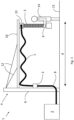
- FIG. 1 schematically shows a vacuum lifting arrangement 1 according to a first example embodiment.
- the vacuum lifting arrangement 1 comprise a vacuum pump 2, a valve arrangement 3, a support structure 4, and a flexible lifting tube 5 comprising a suction foot 6.
- the vacuum pump 2 is connected to the valve arrangement 3 via a first vacuum connection 7.
- the valve arrangement 3 and the flexible lifting tube 5, and thereby the suction foot 6, are connected via a second vacuum connection 8.
- the valve arrangement 3 is arranged to extend and retract the flexible lifting tube 5 upon operation of the valve arrangement 3.
- the valve arrangement 3 is arranged separate from, or at a distance from the suction foot 6, between the vacuum pump 2 and the suction foot 6.
- the valve arrangement 3 and the suction foot 6 are thus physically separated from each other, i.e. the valve arrangement 3 is a separate unit and the suction foot 6 is a separate unit.
- Previous vacuum lifting arrangement 1 comprises suction feet 6 where the valve arrangement 3 is an integral part of the suction feet 6.
- the support structure 4 comprises a vertical support part 9 and a horizontal support part 10 attached to the vertical support part 9 at a distance from a floor 11. Stays or struts 12 may connect the vertical support part 9 and the horizontal support part 10 in order to improve the durability and the lifting capacity of the support structure 4.
- the flexible lifting tube 5 is attached to the support structure 4 via a rotatable connection 13 on the horizontal support part 10 that enables an operator 14 to manoeuvre the suction foot 6 and the flexible lifting tube 5 to a certain degree.
- the construction of the support structure 4 and the attachment of the flexible lifting tube 5 to the horizontal support part 10 are well known in the art.
- the valve arrangement 3 is arranged on the vertical support part of the support structure 4.
- the valve arrangement 3 may also be arranged on a different surface, such as on a wall, on a beam or on a pillar of the room the vacuum lifting arrangement 1 is installed.
- the first vacuum connection 7 and the second vacuum connection 8 may be attached to the vertical support part 9 and/or the horizontal support part 10.
- the suction foot 6 can be made considerably smaller due to the separate placement of the valve arrangement 3.
- the vacuum pump 2 is in figure 1 shown to be placed in the same space as the operator 14. This is not necessary and the vacuum pump 2 may be placed in a different room to reduce the sound coming from the vacuum pump 2.
- the valve arrangement 3 is arranged to be remotely operated by the operator 14 of the suction foot 6. This is achieved by that the suction foot 6 comprises a remote control (not shown) and by that the valve arrangement 3 comprises a valve (not shown) connected to a remote controlled actuating means (not shown) arranged to actuate the valve of the valve arrangement 3.
- the valve and valve actuating means can be of any type suitable for work with a vacuum lifting arrangement 1.
- the remote controlled actuating means is according to one example arranged to be remotely controlled by a hardwired connection between the remote control and the remote controlled actuating means, i.e. a wire connecting the remote control on the suction foot 6 with the remote controlled actuating means.
- the remote controlled actuating means is according to a further example arranged to be remotely controlled by a radio connection between the remote control and the remote controlled actuating means. Suitable radio frequencies for remote control are known in the art.
- the remote controlled actuating means is according to a further example arranged to be remotely controlled by a Bluetooth ® connection between the remote control and the remote controlled actuating means.
- the remote controlled actuating means is according to one example arranged to be remotely controlled by a wireless mobile telecommunications connection between the remote control and the remote controlled actuating means.
- a wireless mobile telecommunications connection between the remote control and the remote controlled actuating means.
- This can for instance be a second generation (2G or 2.5G), third generation (3G), fourth generation (4G) or fifth generation (5G) wireless mobile telecommunications connection.
- Future wireless mobile telecommunications connections could also be conceivable to work with the vacuum lifting arrangement 1 according to the disclosure.
- the remote controlled actuating means is according to one example arranged to be remotely controlled by a Wi-Fi connection between the remote control and the remote controlled actuating means.
- the remote controlled actuating means is according to one example arranged to be remotely controlled by an infrared connection between the remote control and the remote controlled actuating means. This can be useful when line of sight between the remote control and the remote controlled actuating means is available.
- the wire of the hardwired connection can be arranged either inside the flexible lifting tube 5 or on the outside of the flexible lifting tube 5.
- the remote control arranged on the suction foot 6 can be one of a piezoelectric sensor, a pressure sensor, a potentiometer, push buttons, levers or electromechanical control means. Any type of remote control arranged to work with the different connections mentioned above can be integrated into the suction foot 6.
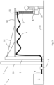
- FIG. 2 schematically shows a vacuum lifting arrangement 1 according to a second example embodiment.
- the difference between the vacuum lifting arrangement 1 of figure 2 and the vacuum lifting arrangement 1 of figure 1 is that in the second example embodiment, the valve arrangement 3 is placed behind a wall 15 together with the vacuum pump 2. This further increases the attenuation of the sound from the valve arrangement 3 and it may be beneficial for servicing the vacuum lifting arrangement 1 to have both the valve arrangement 3 and the vacuum pump 2 placed together. Further, by having the vacuum pump 2 and the valve arrangement 3 placed behind the wall 15, the sound level at the operator 14 can be reduced to a level where hearing protection is no longer needed.
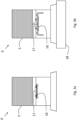
- Figures 3a and 3b schematically show a cross sectional view of a suction foot 6 used with the vacuum lifting arrangement 1 according to the disclosure.
- the suction foot 6 is shown without a load attached to it.
- the suction foot 6 comprises a movable valve plate 16 arranged to close against a seal 17 during operation of the vacuum pump 2 when no load is attached to the suction foot 6.
- the vacuum generated by the vacuum pump 2 causes the valve plate 16 to be pressed towards the seal 17 by the ambient pressure.
- the valve plate 16 is pressed against the seal 17, no more air can pass through the seal 17 and the suction foot 6 is sealed from the ambient air.
- the suction foot 6 is shown with a load 18 attached to it.
- the suction foot 6 With a load 18 attached to the suction foot 6, the suction foot 6 is sealed by the load 18 which means that there is no flow from the vacuum pump 2 passing through the suction foot 6.
- the valve plate 16 drops down from the seal 17.
- the valve plate 16 is arranged on fastening means 19 arranged to limit the movement of the valve plate 16 when no flow from the vacuum pump 6 is present.
- the movable plate 16 can be arranged above the seal 17 such that the weight of the movable plate 16 causes the movable plate 16 to seal against the seal 17 when there is no load 18 attached to the suction foot 6.
- the vacuum created in the suction foot 6 causes the movable plate 16 to release from the seal 17.
- the horizontal support part 10 of the support structure 4 is attached to a vertical support part 9.
- the horizontal support part 10 may alternatively be attached to a wall or a ceiling.
- the horizontal support part 10 can also be attached to a vertical support part 9 attached to a mobile platform so that the entire vacuum lifting arrangement 1 is movable.
Landscapes
- Engineering & Computer Science (AREA)
- Mechanical Engineering (AREA)
- Compressors, Vaccum Pumps And Other Relevant Systems (AREA)
- Hooks, Suction Cups, And Attachment By Adhesive Means (AREA)
- Load-Engaging Elements For Cranes (AREA)
- Invalid Beds And Related Equipment (AREA)
Claims (8)
- Agencement de levage sous vide (1) comprenant une pompe à vide (2), un dispositif de soupape (3), une structure de support (4) et un tube de levage flexible (5) comprenant un pied d'aspiration (6),dans lequel la pompe à vide (2) est reliée au dispositif de soupape (3) et au tube de levage flexible (5), le dispositif de soupape (3) est conçu pour déployer et rétracter le tube de levage flexible (5), le dispositif de soupape (3) est disposé séparément du pied d'aspiration (6), entre la pompe à vide (2) et le pied d'aspiration (6),caractérisé en ce que le pied d'aspiration (6) comprend une plaque de soupape mobile (16) conçue pour se fermer contre un joint d'étanchéité (17) pendant le fonctionnement de la pompe à vide (2) lorsqu'aucune charge n'est appliquée au pied d'aspiration (6).
- Agencement de levage sous vide (1) selon la revendication 1,
dans lequel le dispositif de soupape (3) est conçu pour être actionné à distance par un opérateur (14) du pied d'aspiration (6). - Agencement de levage sous vide (1) selon la revendication 2,dans lequel le pied d'aspiration (6) comprend une télécommande et le dispositif de soupape (3) comprend un moyen d'actionnement télécommandé conçu pour actionner le dispositif de soupape (3),le moyen d'actionnement télécommandé est conçu pour être télécommandé par l'un des éléments suivants :- une connexion câblée entre la télécommande et le moyen d'actionnement télécommandé,- une connexion radio entre la télécommande et le moyen d'actionnement télécommandé,- une connexion Bluetooth® entre la télécommande et le moyen d'actionnement télécommandé,- une connexion de télécommunications mobiles sans fil entre la télécommande et le moyen d'actionnement télécommandé,- une connexion Wi-Fi entre la télécommande et le moyen d'actionnement télécommandé,- une connexion infrarouge entre la télécommande et le moyen d'actionnement télécommandé.
- Agencement de levage sous vide (1) selon la revendication 2,
dans lequel le moyen d'actionnement télécommandé est télécommandé par une connexion câblée entre la télécommande et le moyen d'actionnement télécommandé, et un fil de la connexion câblée est disposé à l'intérieur du tube de levage flexible (5) ou à l'extérieur du tube de levage flexible (5). - Agencement de levage sous vide (1) selon l'une des revendications 2 à 4, dans lequel la télécommande est un capteur piézoélectrique, un capteur de pression, un potentiomètre, des boutons-poussoirs, des leviers ou des moyens de commande électromécaniques.
- Procédé pour fournir un agencement de levage sous vide (1),
dans lequel l'agencement de levage sous vide (1) comprend une pompe à vide (2), un dispositif de soupape (3), une structure de support (4) et un tube de levage flexible (5) comprenant un pied d'aspiration (6), le procédé consistant à :- agencer le dispositif de soupape (3) à connecter à la pompe à vide (2) et au tube de levage flexible (5), le dispositif de soupape (3) étant séparé du pied d'aspiration (6), entre la pompe à vide (2) et le pied d'aspiration (6) ; et- fournir une plaque de soupape mobile (16) à l'intérieur du pied d'aspiration (6), conçue pour se fermer contre un joint d'étanchéité (17) pendant le fonctionnement de la pompe à vide (2) lorsqu'aucune charge n'est appliquée au pied d'aspiration (6). - Procédé selon la revendication 6,le procédé consistant à :- agencer une télécommande sur le pied d'aspiration (6),- agencer un moyen d'actionnement télécommandé sur le dispositif de soupape (3),dans lequel le moyen d'actionnement télécommandé est conçu pour être télécommandé par la télécommande sur le pied d'aspiration (6).
- Procédé selon la revendication 6 ou 7,
dans lequel le moyen d'actionnement télécommandé est télécommandé par une connexion câblée entre la télécommande et le moyen d'actionnement télécommandé, le procédé consistant à :- fournir la connexion câblée à l'intérieur du tube de levage flexible en actionnant la pompe à vide (2) pour aspirer la connexion câblée jusque dans le tube flexible.
Applications Claiming Priority (2)
| Application Number | Priority Date | Filing Date | Title |
|---|---|---|---|
| SE2050020A SE2050020A1 (en) | 2020-01-14 | 2020-01-14 | Vacuum lifting arrangement |
| PCT/SE2021/050015 WO2021145815A1 (fr) | 2020-01-14 | 2021-01-13 | Agencement de levage sous vide et procédé de fourniture d'un tel agencement |
Publications (4)
| Publication Number | Publication Date |
|---|---|
| EP4090622A1 EP4090622A1 (fr) | 2022-11-23 |
| EP4090622A4 EP4090622A4 (fr) | 2024-03-13 |
| EP4090622B1 true EP4090622B1 (fr) | 2024-10-23 |
| EP4090622C0 EP4090622C0 (fr) | 2024-10-23 |
Family
ID=76864761
Family Applications (1)
| Application Number | Title | Priority Date | Filing Date |
|---|---|---|---|
| EP21741810.2A Active EP4090622B1 (fr) | 2020-01-14 | 2021-01-13 | Agencement de levage sous vide et procédé de fourniture d'un tel agencement |
Country Status (6)
| Country | Link |
|---|---|
| US (1) | US11795011B2 (fr) |
| EP (1) | EP4090622B1 (fr) |
| ES (1) | ES2994951T3 (fr) |
| PL (1) | PL4090622T3 (fr) |
| SE (1) | SE2050020A1 (fr) |
| WO (1) | WO2021145815A1 (fr) |
Families Citing this family (5)
| Publication number | Priority date | Publication date | Assignee | Title |
|---|---|---|---|---|
| EP4430627A1 (fr) | 2021-11-11 | 2024-09-18 | Johnson & Johnson Surgical Vision, Inc. | Prédiction de puissance de cristallins artificiels (iol) |
| US12502068B2 (en) | 2021-11-11 | 2025-12-23 | Johnson & Johnson Surgical Vision, Inc. | Prediction of IOL power |
| EP4584198A1 (fr) | 2022-09-05 | 2025-07-16 | Tawi Aktiebolag | Agencement de levage sous vide et tube de levage destiné à être utilisé dans celui-ci |
| DE102023117475B4 (de) * | 2023-07-03 | 2025-05-22 | J.Schmalz Gmbh | Schlauchheber mit Steuerventil |
| EP4588878A1 (fr) | 2024-01-19 | 2025-07-23 | Tawi Aktiebolag | Agencement de tube de levage à vide ayant un tube de levage verrouillable par extension |
Family Cites Families (13)
| Publication number | Priority date | Publication date | Assignee | Title |
|---|---|---|---|---|
| CH526461A (de) * | 1971-02-10 | 1972-08-15 | Gis Ag | Unterdruck-Hebevorrichtung |
| DE3943285A1 (de) * | 1989-01-27 | 1990-08-02 | Aruchemie Ag Wangen | Verfahren zum transportieren von behaeltnissen |
| GB9100056D0 (en) * | 1991-01-03 | 1991-02-20 | Palamatic Handling Syst | Valve arrangement |
| WO1995030615A1 (fr) * | 1994-05-09 | 1995-11-16 | Autocast Inventions Limited | Element formant grille et appareil dans lequel il est integre afin de faciliter la manipulation de produits empilables sur une surface |
| FR2765203B1 (fr) * | 1997-06-25 | 1999-07-30 | Joulin Aero | Perfectionnements aux appareils pneumatiques de manutention |
| DE10151883B4 (de) * | 2001-10-20 | 2007-01-04 | J. Schmalz Gmbh | Pneumatische Unterdruckhandhabungseinrichtung |
| US20060102363A1 (en) * | 2004-11-15 | 2006-05-18 | Michael Tvetene | Sod handler |
| US8511196B2 (en) * | 2009-04-23 | 2013-08-20 | Tandem Technologies, Llc | Traction drive system |
| SE536154C2 (sv) * | 2011-10-25 | 2013-06-04 | Xerex Ab | Insats för bälg med asymmetrisk kompression i vakuumdriven gripanordning |
| US9527697B2 (en) * | 2013-06-05 | 2016-12-27 | Raka Corporation | Articulated jib crane |
| CN205023755U (zh) * | 2015-09-04 | 2016-02-10 | 嘉兴职业技术学院 | 一种带有摇臂功能的气管式真空吸吊机 |
| EP3243608B1 (fr) * | 2016-05-09 | 2022-04-06 | J. Schmalz GmbH | Procede de surveillance des etats de fonctionnement d'un actionneur commande par pression et actionneur commande par pression |
| JP6697496B2 (ja) * | 2018-02-20 | 2020-05-20 | ファナック株式会社 | 吸着パッドおよび吸着パッドの吸着解除方法 |
-
2020
- 2020-01-14 SE SE2050020A patent/SE2050020A1/en not_active Application Discontinuation
-
2021
- 2021-01-13 ES ES21741810T patent/ES2994951T3/es active Active
- 2021-01-13 PL PL21741810.2T patent/PL4090622T3/pl unknown
- 2021-01-13 WO PCT/SE2021/050015 patent/WO2021145815A1/fr not_active Ceased
- 2021-01-13 EP EP21741810.2A patent/EP4090622B1/fr active Active
- 2021-01-13 US US17/792,075 patent/US11795011B2/en active Active
Also Published As
| Publication number | Publication date |
|---|---|
| EP4090622A4 (fr) | 2024-03-13 |
| SE2050020A1 (en) | 2021-09-09 |
| US20230104207A1 (en) | 2023-04-06 |
| EP4090622C0 (fr) | 2024-10-23 |
| PL4090622T3 (pl) | 2025-02-10 |
| WO2021145815A1 (fr) | 2021-07-22 |
| EP4090622A1 (fr) | 2022-11-23 |
| ES2994951T3 (en) | 2025-02-04 |
| US11795011B2 (en) | 2023-10-24 |
Similar Documents
| Publication | Publication Date | Title |
|---|---|---|
| EP4090622B1 (fr) | Agencement de levage sous vide et procédé de fourniture d'un tel agencement | |
| EP1249392A1 (fr) | Coffre de bagages à main actionné par un dispositif à pression réduite | |
| KR900008905B1 (ko) | 유체압 엘리베이터 | |
| JP4871276B2 (ja) | 真空チューブ昇降装置及び該真空チューブ昇降装置による荷物の移動のための方法 | |
| JP2005264938A (ja) | 真空ポンプシステム | |
| US2927661A (en) | Elevator for lifting persons or loads | |
| KR100836351B1 (ko) | 콘크리트 펌프를 위한 분절 마스트 작동장치 | |
| US7946391B2 (en) | Hydraulic elevator without machine room | |
| JP3321102B2 (ja) | 車両用リフト | |
| JPS5820828A (ja) | 潜函における掘削機運転用大気圧カプセルの昇降旋回装置 | |
| KR102392203B1 (ko) | 고압 진공 안전 밸브의 감시 시스템 | |
| US10047770B2 (en) | Patient support apparatus with hydraulic control system | |
| CN116261617B (zh) | 气动伸缩式桅杆 | |
| JP2001027204A (ja) | 油圧装置 | |
| KR102269426B1 (ko) | 차량의 내외부 가속페달 연동 조작지원장치 | |
| US20190315598A1 (en) | Pneumatic vertical transportation device | |
| KR101535302B1 (ko) | 건설기계의 조작패턴 변환장치 | |
| KR200457222Y1 (ko) | 액튜에이터 작동용 내장 유압식 수동 오버라이드장치 | |
| US235121A (en) | Ioisting system | |
| US20120125459A1 (en) | Hydraulic Main Valve and Auxillary Valve | |
| JP2000328608A (ja) | バックホウ | |
| WO2000032508A1 (fr) | Ascenseur | |
| CN223377664U (zh) | 操作手柄与工程机械 | |
| JP2000118916A (ja) | 油圧エレベータの走行装置 | |
| JP2001335292A (ja) | 高所作業車 |
Legal Events
| Date | Code | Title | Description |
|---|---|---|---|
| STAA | Information on the status of an ep patent application or granted ep patent |
Free format text: STATUS: THE INTERNATIONAL PUBLICATION HAS BEEN MADE |
|
| PUAI | Public reference made under article 153(3) epc to a published international application that has entered the european phase |
Free format text: ORIGINAL CODE: 0009012 |
|
| STAA | Information on the status of an ep patent application or granted ep patent |
Free format text: STATUS: REQUEST FOR EXAMINATION WAS MADE |
|
| 17P | Request for examination filed |
Effective date: 20220705 |
|
| AK | Designated contracting states |
Kind code of ref document: A1 Designated state(s): AL AT BE BG CH CY CZ DE DK EE ES FI FR GB GR HR HU IE IS IT LI LT LU LV MC MK MT NL NO PL PT RO RS SE SI SK SM TR |
|
| DAV | Request for validation of the european patent (deleted) | ||
| DAX | Request for extension of the european patent (deleted) | ||
| P01 | Opt-out of the competence of the unified patent court (upc) registered |
Effective date: 20230524 |
|
| A4 | Supplementary search report drawn up and despatched |
Effective date: 20240209 |
|
| RIC1 | Information provided on ipc code assigned before grant |
Ipc: B65G 47/91 20060101ALI20240205BHEP Ipc: B66C 1/02 20060101AFI20240205BHEP |
|
| GRAP | Despatch of communication of intention to grant a patent |
Free format text: ORIGINAL CODE: EPIDOSNIGR1 |
|
| STAA | Information on the status of an ep patent application or granted ep patent |
Free format text: STATUS: GRANT OF PATENT IS INTENDED |
|
| INTG | Intention to grant announced |
Effective date: 20240524 |
|
| GRAS | Grant fee paid |
Free format text: ORIGINAL CODE: EPIDOSNIGR3 |
|
| GRAA | (expected) grant |
Free format text: ORIGINAL CODE: 0009210 |
|
| STAA | Information on the status of an ep patent application or granted ep patent |
Free format text: STATUS: THE PATENT HAS BEEN GRANTED |
|
| AK | Designated contracting states |
Kind code of ref document: B1 Designated state(s): AL AT BE BG CH CY CZ DE DK EE ES FI FR GB GR HR HU IE IS IT LI LT LU LV MC MK MT NL NO PL PT RO RS SE SI SK SM TR |
|
| REG | Reference to a national code |
Ref country code: GB Ref legal event code: FG4D |
|
| REG | Reference to a national code |
Ref country code: CH Ref legal event code: EP |
|
| REG | Reference to a national code |
Ref country code: DE Ref legal event code: R096 Ref document number: 602021020675 Country of ref document: DE |
|
| REG | Reference to a national code |
Ref country code: IE Ref legal event code: FG4D |
|
| P04 | Withdrawal of opt-out of the competence of the unified patent court (upc) registered |
Free format text: CASE NUMBER: APP_61931/2024 Effective date: 20241119 |
|
| U01 | Request for unitary effect filed |
Effective date: 20241118 |
|
| U07 | Unitary effect registered |
Designated state(s): AT BE BG DE DK EE FI FR IT LT LU LV MT NL PT RO SE SI Effective date: 20241122 |
|
| REG | Reference to a national code |
Ref country code: ES Ref legal event code: FG2A Ref document number: 2994951 Country of ref document: ES Kind code of ref document: T3 Effective date: 20250204 |
|
| U20 | Renewal fee for the european patent with unitary effect paid |
Year of fee payment: 5 Effective date: 20250115 |
|
| PG25 | Lapsed in a contracting state [announced via postgrant information from national office to epo] |
Ref country code: IS Free format text: LAPSE BECAUSE OF FAILURE TO SUBMIT A TRANSLATION OF THE DESCRIPTION OR TO PAY THE FEE WITHIN THE PRESCRIBED TIME-LIMIT Effective date: 20250223 Ref country code: HR Free format text: LAPSE BECAUSE OF FAILURE TO SUBMIT A TRANSLATION OF THE DESCRIPTION OR TO PAY THE FEE WITHIN THE PRESCRIBED TIME-LIMIT Effective date: 20241023 |
|
| PG25 | Lapsed in a contracting state [announced via postgrant information from national office to epo] |
Ref country code: NO Free format text: LAPSE BECAUSE OF FAILURE TO SUBMIT A TRANSLATION OF THE DESCRIPTION OR TO PAY THE FEE WITHIN THE PRESCRIBED TIME-LIMIT Effective date: 20250123 |
|
| PG25 | Lapsed in a contracting state [announced via postgrant information from national office to epo] |
Ref country code: GR Free format text: LAPSE BECAUSE OF FAILURE TO SUBMIT A TRANSLATION OF THE DESCRIPTION OR TO PAY THE FEE WITHIN THE PRESCRIBED TIME-LIMIT Effective date: 20250124 |
|
| PG25 | Lapsed in a contracting state [announced via postgrant information from national office to epo] |
Ref country code: RS Free format text: LAPSE BECAUSE OF FAILURE TO SUBMIT A TRANSLATION OF THE DESCRIPTION OR TO PAY THE FEE WITHIN THE PRESCRIBED TIME-LIMIT Effective date: 20250123 |
|
| PG25 | Lapsed in a contracting state [announced via postgrant information from national office to epo] |
Ref country code: SM Free format text: LAPSE BECAUSE OF FAILURE TO SUBMIT A TRANSLATION OF THE DESCRIPTION OR TO PAY THE FEE WITHIN THE PRESCRIBED TIME-LIMIT Effective date: 20241023 |
|
| PG25 | Lapsed in a contracting state [announced via postgrant information from national office to epo] |
Ref country code: SK Free format text: LAPSE BECAUSE OF FAILURE TO SUBMIT A TRANSLATION OF THE DESCRIPTION OR TO PAY THE FEE WITHIN THE PRESCRIBED TIME-LIMIT Effective date: 20241023 |
|
| PLBE | No opposition filed within time limit |
Free format text: ORIGINAL CODE: 0009261 |
|
| STAA | Information on the status of an ep patent application or granted ep patent |
Free format text: STATUS: NO OPPOSITION FILED WITHIN TIME LIMIT |
|
| PG25 | Lapsed in a contracting state [announced via postgrant information from national office to epo] |
Ref country code: MC Free format text: LAPSE BECAUSE OF FAILURE TO SUBMIT A TRANSLATION OF THE DESCRIPTION OR TO PAY THE FEE WITHIN THE PRESCRIBED TIME-LIMIT Effective date: 20241023 |
|
| 26N | No opposition filed |
Effective date: 20250724 |
|
| PG25 | Lapsed in a contracting state [announced via postgrant information from national office to epo] |
Ref country code: IE Free format text: LAPSE BECAUSE OF NON-PAYMENT OF DUE FEES Effective date: 20250113 |
|
| PGFP | Annual fee paid to national office [announced via postgrant information from national office to epo] |
Ref country code: CZ Payment date: 20251218 Year of fee payment: 6 |
|
| PGFP | Annual fee paid to national office [announced via postgrant information from national office to epo] |
Ref country code: PL Payment date: 20251218 Year of fee payment: 6 |
|
| REG | Reference to a national code |
Ref country code: CH Ref legal event code: U11 Free format text: ST27 STATUS EVENT CODE: U-0-0-U10-U11 (AS PROVIDED BY THE NATIONAL OFFICE) Effective date: 20260201 |
|
| U20 | Renewal fee for the european patent with unitary effect paid |
Year of fee payment: 6 Effective date: 20260116 |
|
| PGFP | Annual fee paid to national office [announced via postgrant information from national office to epo] |
Ref country code: GB Payment date: 20260121 Year of fee payment: 6 |
|
| PGFP | Annual fee paid to national office [announced via postgrant information from national office to epo] |
Ref country code: ES Payment date: 20260206 Year of fee payment: 6 |
|
| PGFP | Annual fee paid to national office [announced via postgrant information from national office to epo] |
Ref country code: TR Payment date: 20260107 Year of fee payment: 6 |
|
| PGFP | Annual fee paid to national office [announced via postgrant information from national office to epo] |
Ref country code: CH Payment date: 20260201 Year of fee payment: 6 |