EP4090779B1 - Boulets de broyage forges pour broyeur semi-autogene - Google Patents
Boulets de broyage forges pour broyeur semi-autogene Download PDFInfo
- Publication number
- EP4090779B1 EP4090779B1 EP21701066.9A EP21701066A EP4090779B1 EP 4090779 B1 EP4090779 B1 EP 4090779B1 EP 21701066 A EP21701066 A EP 21701066A EP 4090779 B1 EP4090779 B1 EP 4090779B1
- Authority
- EP
- European Patent Office
- Prior art keywords
- content
- grinding ball
- comprised
- less
- bar
- Prior art date
- Legal status (The legal status is an assumption and is not a legal conclusion. Google has not performed a legal analysis and makes no representation as to the accuracy of the status listed.)
- Active
Links
Images


Classifications
-
- C—CHEMISTRY; METALLURGY
- C22—METALLURGY; FERROUS OR NON-FERROUS ALLOYS; TREATMENT OF ALLOYS OR NON-FERROUS METALS
- C22C—ALLOYS
- C22C38/00—Ferrous alloys, e.g. steel alloys
- C22C38/02—Ferrous alloys, e.g. steel alloys containing silicon
-
- C—CHEMISTRY; METALLURGY
- C21—METALLURGY OF IRON
- C21D—MODIFYING THE PHYSICAL STRUCTURE OF FERROUS METALS; GENERAL DEVICES FOR HEAT TREATMENT OF FERROUS OR NON-FERROUS METALS OR ALLOYS; MAKING METAL MALLEABLE, e.g. BY DECARBURISATION OR TEMPERING
- C21D9/00—Heat treatment, e.g. annealing, hardening, quenching or tempering, adapted for particular articles; Furnaces therefor
- C21D9/36—Heat treatment, e.g. annealing, hardening, quenching or tempering, adapted for particular articles; Furnaces therefor for balls; for rollers
-
- B—PERFORMING OPERATIONS; TRANSPORTING
- B02—CRUSHING, PULVERISING, OR DISINTEGRATING; PREPARATORY TREATMENT OF GRAIN FOR MILLING
- B02C—CRUSHING, PULVERISING, OR DISINTEGRATING IN GENERAL; MILLING GRAIN
- B02C17/00—Disintegrating by tumbling mills, i.e. mills having a container charged with the material to be disintegrated with or without special disintegrating members such as pebbles or balls
- B02C17/18—Details
- B02C17/20—Disintegrating members
-
- C—CHEMISTRY; METALLURGY
- C21—METALLURGY OF IRON
- C21D—MODIFYING THE PHYSICAL STRUCTURE OF FERROUS METALS; GENERAL DEVICES FOR HEAT TREATMENT OF FERROUS OR NON-FERROUS METALS OR ALLOYS; MAKING METAL MALLEABLE, e.g. BY DECARBURISATION OR TEMPERING
- C21D1/00—General methods or devices for heat treatment, e.g. annealing, hardening, quenching or tempering
- C21D1/18—Hardening; Quenching with or without subsequent tempering
-
- C—CHEMISTRY; METALLURGY
- C22—METALLURGY; FERROUS OR NON-FERROUS ALLOYS; TREATMENT OF ALLOYS OR NON-FERROUS METALS
- C22C—ALLOYS
- C22C38/00—Ferrous alloys, e.g. steel alloys
- C22C38/04—Ferrous alloys, e.g. steel alloys containing manganese
-
- C—CHEMISTRY; METALLURGY
- C22—METALLURGY; FERROUS OR NON-FERROUS ALLOYS; TREATMENT OF ALLOYS OR NON-FERROUS METALS
- C22C—ALLOYS
- C22C38/00—Ferrous alloys, e.g. steel alloys
- C22C38/18—Ferrous alloys, e.g. steel alloys containing chromium
-
- C—CHEMISTRY; METALLURGY
- C22—METALLURGY; FERROUS OR NON-FERROUS ALLOYS; TREATMENT OF ALLOYS OR NON-FERROUS METALS
- C22C—ALLOYS
- C22C38/00—Ferrous alloys, e.g. steel alloys
- C22C38/18—Ferrous alloys, e.g. steel alloys containing chromium
- C22C38/22—Ferrous alloys, e.g. steel alloys containing chromium with molybdenum or tungsten
-
- C—CHEMISTRY; METALLURGY
- C22—METALLURGY; FERROUS OR NON-FERROUS ALLOYS; TREATMENT OF ALLOYS OR NON-FERROUS METALS
- C22C—ALLOYS
- C22C38/00—Ferrous alloys, e.g. steel alloys
- C22C38/18—Ferrous alloys, e.g. steel alloys containing chromium
- C22C38/36—Ferrous alloys, e.g. steel alloys containing chromium with more than 1.7% by weight of carbon
-
- C—CHEMISTRY; METALLURGY
- C22—METALLURGY; FERROUS OR NON-FERROUS ALLOYS; TREATMENT OF ALLOYS OR NON-FERROUS METALS
- C22C—ALLOYS
- C22C38/00—Ferrous alloys, e.g. steel alloys
- C22C38/18—Ferrous alloys, e.g. steel alloys containing chromium
- C22C38/38—Ferrous alloys, e.g. steel alloys containing chromium with more than 1.5% by weight of manganese
-
- C—CHEMISTRY; METALLURGY
- C22—METALLURGY; FERROUS OR NON-FERROUS ALLOYS; TREATMENT OF ALLOYS OR NON-FERROUS METALS
- C22C—ALLOYS
- C22C38/00—Ferrous alloys, e.g. steel alloys
- C22C38/18—Ferrous alloys, e.g. steel alloys containing chromium
- C22C38/40—Ferrous alloys, e.g. steel alloys containing chromium with nickel
- C22C38/44—Ferrous alloys, e.g. steel alloys containing chromium with nickel with molybdenum or tungsten
-
- C—CHEMISTRY; METALLURGY
- C22—METALLURGY; FERROUS OR NON-FERROUS ALLOYS; TREATMENT OF ALLOYS OR NON-FERROUS METALS
- C22C—ALLOYS
- C22C38/00—Ferrous alloys, e.g. steel alloys
- C22C38/18—Ferrous alloys, e.g. steel alloys containing chromium
- C22C38/40—Ferrous alloys, e.g. steel alloys containing chromium with nickel
- C22C38/56—Ferrous alloys, e.g. steel alloys containing chromium with nickel with more than 1.7% by weight of carbon
-
- C—CHEMISTRY; METALLURGY
- C22—METALLURGY; FERROUS OR NON-FERROUS ALLOYS; TREATMENT OF ALLOYS OR NON-FERROUS METALS
- C22C—ALLOYS
- C22C38/00—Ferrous alloys, e.g. steel alloys
- C22C38/18—Ferrous alloys, e.g. steel alloys containing chromium
- C22C38/40—Ferrous alloys, e.g. steel alloys containing chromium with nickel
- C22C38/58—Ferrous alloys, e.g. steel alloys containing chromium with nickel with more than 1.5% by weight of manganese
-
- C—CHEMISTRY; METALLURGY
- C21—METALLURGY OF IRON
- C21D—MODIFYING THE PHYSICAL STRUCTURE OF FERROUS METALS; GENERAL DEVICES FOR HEAT TREATMENT OF FERROUS OR NON-FERROUS METALS OR ALLOYS; MAKING METAL MALLEABLE, e.g. BY DECARBURISATION OR TEMPERING
- C21D2211/00—Microstructure comprising significant phases
- C21D2211/001—Austenite
-
- C—CHEMISTRY; METALLURGY
- C21—METALLURGY OF IRON
- C21D—MODIFYING THE PHYSICAL STRUCTURE OF FERROUS METALS; GENERAL DEVICES FOR HEAT TREATMENT OF FERROUS OR NON-FERROUS METALS OR ALLOYS; MAKING METAL MALLEABLE, e.g. BY DECARBURISATION OR TEMPERING
- C21D2211/00—Microstructure comprising significant phases
- C21D2211/002—Bainite
-
- C—CHEMISTRY; METALLURGY
- C21—METALLURGY OF IRON
- C21D—MODIFYING THE PHYSICAL STRUCTURE OF FERROUS METALS; GENERAL DEVICES FOR HEAT TREATMENT OF FERROUS OR NON-FERROUS METALS OR ALLOYS; MAKING METAL MALLEABLE, e.g. BY DECARBURISATION OR TEMPERING
- C21D2211/00—Microstructure comprising significant phases
- C21D2211/004—Dispersions; Precipitations
-
- C—CHEMISTRY; METALLURGY
- C21—METALLURGY OF IRON
- C21D—MODIFYING THE PHYSICAL STRUCTURE OF FERROUS METALS; GENERAL DEVICES FOR HEAT TREATMENT OF FERROUS OR NON-FERROUS METALS OR ALLOYS; MAKING METAL MALLEABLE, e.g. BY DECARBURISATION OR TEMPERING
- C21D2211/00—Microstructure comprising significant phases
- C21D2211/008—Martensite
-
- C—CHEMISTRY; METALLURGY
- C21—METALLURGY OF IRON
- C21D—MODIFYING THE PHYSICAL STRUCTURE OF FERROUS METALS; GENERAL DEVICES FOR HEAT TREATMENT OF FERROUS OR NON-FERROUS METALS OR ALLOYS; MAKING METAL MALLEABLE, e.g. BY DECARBURISATION OR TEMPERING
- C21D2211/00—Microstructure comprising significant phases
- C21D2211/009—Pearlite
Definitions
- the present invention relates to cast iron grinding balls with a high chromium content, intended for semi-autogenous grinding. It also relates to the manufacturing process of said balls.
- the current process is based on a semi-autogenous rotary mill and one or more rotary ball mills. Such a process line can be duplicated depending on the desired flow rate or the types of ores existing in the mine.
- the semi-autogenous grinder is characterized by an original design.
- the diameter is very large, more than five meters in general, with a proportionally short length. It is characterized by a length to diameter ratio generally less than 1, preferably between 0.5 and 1.
- the ore supply made continuously, comes directly from the mine or from a crushing section. A varying amount of water is added to ore blocks of different sizes. The flow rates are very high, often well over 1000 tonnes per hour.
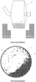
- FIGS. 1A and 1B show a semi-autogenous crusher 1.
- These crushers include shields 2 with protruding parts called lifters 3, which allow very intensive lifting. When the crusher is rotating around its horizontal axis, the pieces of rock are lifted and fall back onto the rock bed in the part lower. In addition, through relative movement between blocks and impacts linked to rotation, the material is significantly reduced in size, which justifies the term “autogenous grinding”.
- the grinding balls used in semi-autogenous mills must have good impact resistance as well as good wear resistance. Indeed, the balls used in the semi-autogenous mill are subject to significant wear by abrasion and numerous impacts. This is due to the combined action of very hard minerals in the form of large blocks and often presenting sharp edges and to destruction by rupture and spalling, in relation to the impact conditions inside this equipment. Worn or broken balls of smaller size are no longer effective in their role of crushing the critical size blocks which accumulate in the crusher. These small balls also exit the crusher through open orifices existing in the discharge grid of the semi-autogenous crusher.
- low-alloy carbon steel balls contain by weight 0.4 to 0.9% carbon, less than 1% manganese, chromium and silicon as well as elements in smaller quantities such as molybdenum, vanadium, titanium, niobium as well as impurities more harmful such as sulfur and phosphorus for example. These balls are shaped by forging a bar resulting from casting.
- chrome cast iron balls with a chromium content greater than or equal to 5% by weight, which are directly shaped by casting into a sand or metal mold.
- These alloys have the characteristic of containing chromium carbides, called primary, which appear during solidification during casting. These are M 7 C 3 type carbides.
- austenite cells free of carbides appear first.
- lattice carbides form at the eutectic point around these austenite cells.
- THE Figures 2A and 2B typically represent the distribution of carbides in a cast iron shaped by casting into a mold. We observe at the Figure 2A the network distribution of carbides 5 which formed between the austenite dendrites during solidification.
- the concentration section generally by flotation for sulphide ores such as copper or lead and zinc.
- sulphide ores such as copper or lead and zinc.
- the presence of chromium makes it possible to obtain a better quality pulp with, as a corollary, a reduction in the quantity of reagent required.
- the chromium content must, however, be perfectly dosed to avoid additional costs linked to the addition of chromium.
- the carbide and therefore carbon content must also be perfectly controlled in cast iron to avoid weakening of the material due to excess carbides.
- grinding balls forged in white cast iron with a high chromium content obtained from a bar manufactured by continuous casting.
- the grinding balls have a carbon content of between 1.5 and 3% by weight and a chromium content of between 8 and 25%.
- the grinding balls have a carbon content of between 1.7 and 2.15% by weight and a chromium content of between 5.3 and 8%.
- the present invention proposes a grinding ball having the advantages of low-alloy steels as well as the advantages of chrome cast irons, that is to say having both good impact resistance and good wear resistance. while having an optimized chromium content for the concentration section. To do this, according to the invention, the composition and the manufacturing process are optimized. The present invention proposes this type of ball in particular for use in the context of a semi-autogenous grinding process.
- the carbon content is maintained in the range 1.1-1.4% by weight to obtain the sufficient but not too large quantity of carbides in order to avoid weakening the ball.
- the chromium content is maintained in the 10-14% range to obtain a matrix sufficiently rich in chromium for better recovery after grinding while avoiding additional costs linked to the addition of chromium.
- the carbon content and the chromium content are correlated according to the following inequalities: 2.55 ⁇ Cr ⁇ 5.42 * VS ⁇ 7.67 And 41.76 ⁇ Cr + 28.66 * VS ⁇ 53.69 .
- the carbides are finely distributed within the microstructure of the ball. Preferably, they have an equivalent diameter of less than 100 ⁇ m, more preferably less than 50 ⁇ m and even more preferably less than 20 ⁇ m.
- the microstructure includes a matrix in which the chromium carbides are distributed.
- the microstructure comprises martensite with a percentage greater than 50%, residual austenite with a percentage between 7 and 25%, a total fraction of pearlite and bainite between 2 and 10%, the balance being made up of chromium carbides with a percentage less than or equal to 22%.
- the present invention relates to the process for manufacturing grinding balls and to grinding balls more specifically intended for application in a semi-autogenous mill. Typically, these are balls having a diameter between 90 mm and 150 mm.
- the chromium content and the carbon content are jointly and respectively maintained in the range 10-14% and 1.1-1.4%.
- carbon content and chromium content are closely related.
- the dotted lines, called conodes are lines representing alloys having the same matrix composition, that is to say, among other things, the same chromium content in the matrix. Moving from one conode to another following the solid line arrow results in an increase in the chromium content in the matrix. On the other hand, when moving along a conode, the composition of the matrix remains unchanged but the carbide content evolves and increases as we move in the direction of the arrow in dotted lines.
- the carbon and chromium contents are correlated according to the two inequalities: 2.55 ⁇ Cr-5.42*C ⁇ 7.67 and 41.76 ⁇ Cr+28.66*C ⁇ 53.69.
- the ball according to the invention has a predominantly martensitic microstructure, i.e. with a percentage of martensite greater than 50%, with a fine and homogeneous distribution of chromium carbides, called primary carbides, of type M 7 C 3 within the matrix.
- the average of the equivalent diameters is carried out on the basis of measurements taken on at least three images.
- the measurements are, for example, taken on images having a size of 660 ⁇ m x 495 ⁇ m.
- the size of the carbides is substantially homogeneous between the surface and the core of the ball with the manufacturing process described below.
- the continuous casting step is illustrated using the figure 5 , more specifically for horizontal continuous casting. This technique promotes fine-grain solidification by rapid cooling in a shell 9 cooled by water circulation.
- the installation includes a tank of liquid metal, called a casting ladle 8, serving as a buffer between the melting equipment which is an induction furnace 6a or an arc furnace 7, and the horizontal continuous casting.
- Solidification (the liquid part is referenced 12a) is initiated in the shell 9 made of copper alloy combining good thermal conductivity and good resistance to wear by friction, possibly followed by a graphite part enclosed in a copper envelope cooled with water and possibly followed by secondary cooling by water jets.
- the internal morphology of this copper or composite shell takes into account the specific contraction linked to the composition of the alloy which will pass from the liquid state to the solid state.
- the bar 12 or billet begins to solidify in this part of the equipment and then continues to solidify towards the center in the ambient air with movement exerted by an extraction system 10. Sometimes, certain short movements against the direction of extraction are possible to improve the quality of the surface of the billet.
- the bar 12 is then subjected to a magnetic stirring system 11 before the cutting equipment 13 which cuts the bar 12 to the chosen length. It will be noted that several magnetic stirring systems can, if necessary, be used on the continuous casting line.
- a first parameter is the casting temperature which must be as close as possible to the solidification temperature but compatible with industrial production.
- a overheating of 5 to 40°C above the solidification temperature will be the rule, however preferring an overheating of 10 to 15°C. This technique ensures good internal health of the billet by reducing shrinkage in the liquid metal.
- the water jets will be controlled to accelerate solidification while avoiding the formation of cracks on the surface.
- the extraction speed and the extraction step out of the shell must be adapted to the cast alloy.
- Programming the extraction speed can be complex with stops and jerks, even acceleration and braking.
- the extraction pitch for a 90 mm round billet will be between 4 and 12 mm and preferably around 7 to 8 mm.
- the extraction speed will be between 50 and 250 steps per minute and preferably around 150 steps per minute.
- magnetic stirrers can be placed in different locations to ensure the internal health of the bar. Indeed, the solidification is of the dendritic type and develops from the surface initially in contact with the copper shell. Then, the dendrites continue to grow towards the center, those corresponding to the bottom of the billet will grow more quickly given gravity; temperature gradients can also be created in the not yet solidified volume of the solidifying billet, which sometimes increases the risk of a central defect.
- a first electromagnetic stirrer can be positioned around the shell allowing a relatively low but homogeneous casting temperature.
- a second stirrer can be positioned at the end of the pour when the solidified thickness is approximately 20 mm.
- the electromagnetic stirrer could be placed at a distance corresponding to the end of solidification of said billet, i.e. approximately 7 m from the shell.
- the structure includes a fine distribution of chromium carbides, called primary carbides, of the M 7 C 3 type, which appear during eutectic solidification.
- primary carbides of the M 7 C 3 type
- Two optical microscopies and their schematic representations are given respectively to figures 3A And 3B (after forging).
- the carbides 5 do not appear in the form of a network but rather with a discrete distribution within the matrix.
- These primary carbides distributed in a point or in other words discrete manner as opposed to a network distribution, provide improved abrasion resistance without deteriorating the impact resistance properties.
- the carbides can have a certain orientation which is given by the subsequent deformation sequences.
- the size of the solidification grain is reduced thanks to the rapid and directed solidification of the continuous casting step according to the invention as well as by the use of the magnetic stirrer(s).
- This grain fineness also contributes, but to a lesser extent, to improving impact resistance.
- the interpolation method is used. For a known length, we count the number of grains crossed in the direction figure 4A . A reference length is chosen arbitrarily, i.e. 200 ⁇ m for example. The numbers on the right side give the number of intersections. This method is repeated in the other direction Y. In the example illustrated, an average value of 35 ⁇ m is obtained in X and 100 ⁇ m in Y, i.e. a general average of 67 ⁇ m.
- the size of the solidification grain is less than 90 ⁇ m, preferably less than 80 ⁇ m and particularly preferably between 30 and 70 ⁇ m especially in the first 15 millimeters below the surface, preferably 20 mm, or even 25 mm below the surface.
- the grain size obtained by foundry in a sand mold is 100 to 400 ⁇ m and 100 to 200 ⁇ m in a metal mold.
- the shaping step which can be carried out by rolling and/or forging. It is illustrated using the figures 6 to 8 . It can be produced by rolling in a train of fluted cylinders gradually forming the ball. More often, it is carried out by forging in a press 16 of a piece 18 cut from the bar 12 as illustrated in figures 7 and 8 . It is also possible to carry out a first rolling to reduce the diameter of the bar as illustrated in Figure 6 and then put the pieces from the bar into ball shape in the forging press. It is also possible to carry out a rolling sequence following forging in the press to perfect the sphericity of the ball coming from the press.
- the bar 12 is reheated in a pushing furnace 14 or through a series of induction furnaces 6b in the austenitic domain before being rolled in the rolling stands 15, to reduce the thickness of the bar and close the possible porosities. Then, the rolled bar 12 is reheated again in these same types of ovens 14.6b in the austenitic domain before being introduced into the forging press 16 ( Figure 7 ). Typically, reheating is carried out at a temperature between 950 and 1250°C. The bar 12 is then cut by the knife 17 into a piece 18 which is introduced into the press 16 comprising, in the example illustrated, a fixed part 16a and a mobile part 16b.
- the piece 18 is deformed into a blank having the shape of the ball 19 by the movable part 16b moved towards the fixed part 16a.
- the sphericity of the blank can then be improved by passing it between two cylinders having a shape close to an Archimedes screw.
- the blank in ball form is then subjected to heat treatment in one or more cycles to obtain the final product.
- Austenitization is carried out in a temperature range between 880 and 1075°C for a time of between 30 minutes and 3 hours.
- this cycle can be carried out in several stages with a first stage of maintaining a temperature between 620 and 730°C for a time of between 15 minutes and two hours followed by the second maintaining between 880 and 1075°C for a time of between 15 minutes and two hours. between 30 minutes and 3 hours.
- the blank is quenched to a temperature below 220°C to form the martensite.
- Quenching can be done in oil, water, air blast, polymer, etc.
- This austenitization and quenching cycle can be followed by a stress-relieving temper at a temperature of between 150 and 400°C for a time of between 30 minutes and 6 hours.
- the purpose of this relaxation income is to slightly reduce the internal tensions generated by the transformation of austenite into martensite.
- a microstructure is obtained with a matrix comprising martensite in a percentage greater than 50%, preferably between 60 and 80%, residual austenite with a percentage between 7 and 25 % and preferably between 10 and 20%, and a fraction of perlite and bainite comprised in total between 2 and 10%.
- the microstructure comprises the primary carbides distributed in the matrix and possibly some secondary carbides of the M 23 C 6 type, formed during the heat treatment cycles. The microstructure thus comprises for a total percentage of 100%, the aforementioned structures with a balance consisting of chromium carbides with a percentage of up to 22%.
- the fraction of residual austenite is measured by X-ray diffraction according to the ASTM E975-13 standard and the fractions of the other phases are measured by image analysis.
- the final properties are a hardness of 54 to 65 Rc and more generally close to 60 Rc, the Rockwell C hardness being measured according to the ISO6508-1:2016 standard.
- the grinding balls according to the invention thus have excellent resistance to wear conferred in a known manner by the high hardness of the alloy obtained thanks to the presence of martensite and chromium carbides.
- this excellent wear resistance is combined with very good impact resistance properties thanks to the fine distribution of primary carbides as well as the reduced size of the solidification grains.
- the impact resistance properties were tested and compared with those of high chromium cast iron grinding balls shaped by casting according to the prior art.
- the test is based on a technical article from the US Bureau of Mines ( R. Collinsensderfer and JH Tylczak, Minerals & Metallurgical processing, May 1989, pp 60-66 ).
- the test consists of dropping, for each of the two types of balls, 46 balls with a diameter of 125 mm from a height of 10 m.
- the test is carried out in cycles with each of the balls released successively and then re-entered into the loop to be released again.
- the balls are regularly weighed. If the weight loss is greater than 50%, the test is stopped.
- the basic specification is a minimum of 60,000 impacts.
- the grinding balls according to the invention thus have excellent wear resistance with impact resistance properties at least equal to those of conventional forged carbon steels.
Landscapes
- Chemical & Material Sciences (AREA)
- Engineering & Computer Science (AREA)
- Materials Engineering (AREA)
- Mechanical Engineering (AREA)
- Metallurgy (AREA)
- Organic Chemistry (AREA)
- Physics & Mathematics (AREA)
- Thermal Sciences (AREA)
- Crystallography & Structural Chemistry (AREA)
- Food Science & Technology (AREA)
- Crushing And Grinding (AREA)
- Heat Treatment Of Steel (AREA)
- Forging (AREA)
- Grinding And Polishing Of Tertiary Curved Surfaces And Surfaces With Complex Shapes (AREA)
- Grinding Of Cylindrical And Plane Surfaces (AREA)
Description
- La présente invention se rapporte à des boulets de broyage en fonte à haute teneur en chrome, destinés au broyage semi-autogène. Elle se rapporte également au procédé de fabrication desdits boulets.
- Le broyage dans l'industrie minière est destiné à libérer les particules valorisables de minéraux métalliques hors de la gangue constituée de minéraux stériles mais souvent très abrasifs. Les usines sont constituées de stations de concassage, de broyage puis de sections de concentration généralement par flottation pour les minerais sulfurés tels que le cuivre ou le plomb et le zinc, souvent associés.
- Dans la section de broyage de ces usines, le procédé actuel est basé sur un broyeur rotatif semi-autogène et un ou plusieurs broyeurs rotatifs à boulets. Une telle ligne de procédé peut être dupliquée suivant le débit souhaité ou les types de minerais existant dans la mine.
- Le broyeur semi-autogène se caractérise par une conception originale. Le diamètre est très important, plus de cinq mètres en général, avec une longueur proportionnellement courte. On le caractérise par un rapport longueur sur diamètre généralement inférieur à 1, de préférence compris entre 0,5 et 1. L'alimentation en minerais, faite en continu, provient directement de la mine ou d'une section de concassage. Une quantité variable d'eau est ajoutée aux blocs de minerais de différentes dimensions. Les débits sont très importants, souvent très supérieurs à 1000 tonnes par heure.
- Ces broyeurs sont protégés par des blindages permettant de soulever la matière à broyer. Les
figures 1A et 1B montrent un broyeur semi-autogène 1. Ces broyeurs comportent des blindages 2 avec des parties protubérantes appelées releveurs 3, qui permettent un relevage très intensif. Lorsque le broyeur est en rotation autour de son axe horizontal, les morceaux de roches sont soulevés et retombent sur le lit de roches dans la partie inférieure. De plus, par un mouvement relatif entre blocs et les impacts liés à la rotation, la matière se réduit en dimension de manière importante, ce qui justifie le vocable « broyage autogène ». - Pour certains minerais très durs, la taille des roches ne se réduit plus lorsqu'elles atteignent une certaine dimension critique et s'accumulent dans le broyeur en diminuant son efficacité. Pour limiter cet effet, une petite quantité de gros boulets est ajoutée, occupant généralement entre 8 et 12% du volume disponible dans le broyeur. Ces boulets ont des dimensions supérieures à 100 mm, souvent 125 mm et parfois 160 mm et pèsent jusqu'à 16kg chacun. Entraînés par les releveurs, ils vont s'écraser dans le meilleur des cas, après une chute de 5 à 7 m, sur les roches et aider au concassage des blocs durs et difficiles à broyer. Cette méthodologie correspond à l'appellation de broyage semi-autogène. Le broyeur semi-autogène est décrit en détail aux pages internet suivantes :
- https://www.911metallurgist.com/blog/sag-mill-ball-size-evaluator-evaluation-factors
- http://ffden-2.phys.uaf.edu/211_fall2002.web.dir/keith_palchikoff/grinding_mill_2.html
- Les boulets de broyage utilisés dans les broyeurs semi-autogènes doivent présenter une bonne résistance à l'impact ainsi qu'une bonne résistance à l'usure. En effet, les boulets utilisés dans le broyeur semi-autogène sont soumis à une usure importante par abrasion et à de nombreux impacts. Ceci est dû à l'action combinée de minéraux très durs sous forme de gros blocs et présentant souvent des arêtes coupantes et à une destruction par rupture et écaillage, en relation avec les conditions d'impacts à l'intérieur de cet équipement. Les boulets usés ou cassés de dimension plus réduites ne sont plus efficaces dans leur rôle de concassage des blocs de taille critique qui s'accumulent dans le broyeur. Ces petits boulets sortent d'ailleurs du broyeur par des orifices ouverts existant dans la grille de décharge du broyeur semi-autogène.
- Pour combiner au mieux les propriétés de résistance à l'usure et de résistance à l'impact, on utilise généralement deux types de boulets.
- Il y a, d'une part, les boulets en acier au carbone peu allié. Ces aciers comportent en poids de 0.4 à 0.9% de carbone, moins de 1% de manganèse, de chrome et de silicium ainsi que des éléments en plus faibles quantités tels que le molybdène, le vanadium, le titane, le niobium ainsi que des impuretés plus néfastes comme le soufre et le phosphore par exemple. Ces boulets sont mis en forme par forgeage d'une barre issue de la coulée.
- Il y a, d'autre part, les boulets en fonte au chrome, avec une teneur en chrome supérieure ou égale à 5% en poids, qui sont directement mis en forme par coulée dans un moule en sable ou métallique. Ces alliages ont pour caractéristique de comporter des carbures de chrome, dits primaires, qui apparaissent lors de la solidification à la coulée. Il s'agit de carbures de type M7C3. Lors de la solidification, des cellules d'austénite vierges de carbures apparaissent en premier. Ensuite, des carbures en réseau se forment au point eutectique autour de ces cellules d'austénite. Les
figures 2A et 2B représentent typiquement la répartition des carbures dans une fonte mise en forme par coulée dans un moule. On observe à lafigure 2A la répartition en réseau des carbures 5 qui s'est formée entre les dendrites d'austénite lors de la solidification. Lafigure 2B représente schématiquement ces mêmes carbures en réseau. On observe ainsi un réseau de carbures 5 distribués au sein d'une matrice 4 dépourvue du réseau quasi continu de carbures primaires. Ces carbures permettent d'améliorer les propriétés d'usure par rapport aux aciers susmentionnés mais par contre leur répartition inhomogène et grossière détériore les propriétés de résistance à l'impact comparé à ces mêmes aciers. - La mise en forme par forgeage sur les alliages en fonte au chrome a par ailleurs toujours été proscrite car ces carbures grossiers initient la formation de fissures lors du forgeage. Les aciers peu alliés, dépourvus par définition de carbures de chrome, ne sont pas confrontés à ce problème, ce qui a permis d'élaborer des procédés de mise en forme par forgeage sur ces nuances.
- On a ainsi, selon l'art antérieur, d'une part, des aciers peu alliés qui ont une bonne résistance à l'impact et une résistance à l'usure moyenne et, d'autre part, des fontes à haut chrome qui ont une bonne résistance à l'usure mais une résistance à l'impact moyenne.
- Comme susmentionné ci-avant, à la suite de la section de broyage, il y a la section de concentration généralement par flottation pour les minerais sulfurés tels que le cuivre ou le plomb et le zinc. Il s'avère que l'enrichissement en chrome dans les boulets réalisés en fonte permet d'optimiser les étapes de flottation qui se déroulent lors de la récupération dans cette section. La présence de chrome permet d'obtenir une pulpe de meilleure qualité avec, pour corollaire, une réduction de la quantité de réactif nécessaire. La teneur en chrome doit cependant être parfaitement dosée pour éviter un surcoût lié à l'ajout de chrome. En parallèle, la teneur en carbures et donc en carbone doit également être parfaitement maîtrisée dans les fontes pour éviter une fragilisation du matériau par excès de carbures.
- Des documents
US 4 221 612 ,US 3 961 994 etCN 103 710 646 , on connaît des boulets de broyage forgés en fonte blanche au chrome avec différentes teneurs en carbone et en chrome. - Ainsi, du document
US 4 221 612 , on connaît des boulets de broyage forgés en fonte blanche au chrome obtenus partant d'une barre fabriquée par moulage en coquille ou par coulée continue. Les boulets de broyage ont en poids une teneur en carbone comprise entre 1 et 3% et une teneur en chrome comprise entre 2 et 8%. - Du document
US 3 961 994 , on connaît des boulets de broyage forgés en fonte blanche à haute teneur en chrome obtenus partant d'une barre fabriquée par coulée continue. Les boulets de broyage ont en poids une teneur en carbone comprise entre 1.5 et 3% et une teneur en chrome comprise entre 8 et 25%. - Du document
CN 103 710 646 , on connaît des boulets de broyage obtenus par moulage. Les boulets de broyage ont en poids une teneur en carbone comprise entre 1.7 et 2.15% et une teneur en chrome comprise entre 5.3 et 8%. - La présente invention propose un boulet de broyage présentant les avantages des aciers peu alliés ainsi que les avantages des fontes au chrome, c'est-à-dire présentant aussi bien une bonne résistance à l'impact qu'une bonne résistance à l'usure tout en ayant une teneur en chrome optimisée pour la section de concentration. Pour se faire, selon l'invention, la composition et le procédé de fabrication sont optimisés. La présente invention propose ce type de boulet en particulier pour une utilisation dans le cadre d'un procédé de broyage semi-autogène.
- La présente invention est définie dans les revendications annexées, et se rapporte à un boulet de broyage comprenant en poids:
- du carbone avec une teneur comprise entre 1.1 et 1.4%,
- du chrome avec une teneur comprise entre 10 et 14%,
- du manganèse avec une teneur comprise entre 0.8 et 1.5%,
- du silicium avec une teneur comprise entre 0.6 et 1%,
- du molybdène avec une teneur inférieure à 1 %,
- du nickel avec une teneur inférieure à 1%,
- des impuretés éventuelles avec une teneur totale inférieure à 0.5%,
- la balance pour obtenir 100% étant du fer,
- La teneur en carbone est maintenue dans la gamme 1.1-1.4% en poids pour obtenir la quantité suffisante mais pas trop importante de carbures afin d'éviter de fragiliser le boulet. Conjointement, la teneur en chrome est maintenue dans la gamme 10-14% pour obtenir une matrice suffisamment riche en chrome pour une meilleure récupération après le broyage tout en évitant un surcoût lié à l'ajout de chrome. De préférence, la teneur en carbone et la teneur en chrome sont corrélées selon les inéquations suivantes :

- En outre, les carbures sont finement répartis au sein de la microstructure du boulet. Préférentiellement, ils ont un diamètre équivalent inférieur à 100 µm, plus préférentiellement inférieur à 50 µm et encore plus préférentiellement inférieur à 20 µm.
- La microstructure comprend une matrice dans laquelle sont répartis les carbures de chrome. Dans l'invention, la microstructure comprend de la martensite avec un pourcentage supérieur à 50%, de l'austénite résiduelle avec un pourcentage compris entre 7 et 25%, une fraction totale de perlite et de bainite comprise entre 2 et 10%, la balance étant constituée des carbures de chrome avec un pourcentage inférieur ou égal à 22%.
- La présente invention se rapporte également au procédé de fabrication de ce boulet de broyage comportant les étapes suivantes :
- Elaboration par coulée continue d'une barre ayant la composition chimique précitée pour obtenir la répartition discrète de carbures de chrome,
- Mise en forme par déformation en une ou plusieurs séquences de la barre pour obtenir une ébauche de la forme du boulet de broyage,
- Traitement thermique en un ou plusieurs cycles de l'ébauche pour obtenir le boulet de broyage avec une microstructure majoritairement martensitique.
-
- La
figure 1A représente une vue schématique d'un broyeur semi-autogène. - La
figure 1B illustre le mécanisme de broyage au sein du broyeur semi-autogène. - La
figure 2A est une métallographie optique d'un boulet en fonte à haut chrome mis à forme par coulée dans un moule selon l'art antérieur. Lafigure 2B est une représentation schématique de la répartition des carbures de lafigure 2A . - La
figure 3A représente deux métallographies optiques d'un boulet en fonte à haut chrome mis à forme par forgeage après la coulée continue selon l'invention. Lafigure 3B est une représentation schématique de la répartition des carbures de lafigure 3A . - Les
figures 4A et 4B illustrent la méthode de mesure du nombre de grains mesurés respectivement selon l'axe X et l'axe Y permettant d'évaluer la taille moyenne des grains. - La
figure 5 est une représentation schématique de l'étape de coulée continue mise en oeuvre dans le procédé selon l'invention. - La
figure 6 illustre schématiquement à la suite de lafigure 5 l'étape optionnelle de laminage de la barre issue de la coulée continue. - La
figure 7 illustre schématiquement à la suite de lafigure 5 ou de lafigure 6 l'étape de forgeage de la barre issue de la coulée continue ou du laminage. - La
figure 8 illustre plus en détail l'étape de forgeage. - La
figure 9 illustre l'effet conjoint du carbone et du chrome sur la composition de la matrice et sur la teneur en carbures. -
- 1. Broyeur semi-autogène
- 2. Blindage
- 3. Releveur
- 4. Matrice
- 5. Carbure
- 6. Four à induction
- a. de coulée
- b. de réchauffage
- 7. Four à arc
- 8. Poche de coulée
- 9. Coquille
- 10. Système d'extraction
- 11. Système de brassage magnétique
- 12. Barre
- a. Partie liquide
- 13. Equipement de découpe
- 14. Four poussant
- 15. Laminoir
- 16. Presse de forgeage
- a. Partie fixe
- b. Partie mobile
- 17. Couteau
- 18. Lopin
- 19. Boulet de broyage
- La présente invention se rapporte au procédé de fabrication des boulets de broyage et aux boulets de broyage plus spécifiquement destinés à une application dans un broyeur semi-autogène. Typiquement, il s'agit de boulets ayant un diamètre compris entre 90 mm et 150 mm.
- Le boulet de broyage est réalisé dans une fonte à haut chrome ayant la composition suivante en poids (exclue de l'invention):
- du carbone avec une teneur comprise entre 1 et 2%,
- du chrome avec une teneur comprise entre 7 à 16%,
- du manganèse avec une teneur comprise entre 0.5 et 3%,
- du silicium avec une teneur comprise entre 0.2 à 1.5%,
- du molybdène avec une teneur inférieure à 1.5%,
- du nickel avec une teneur inférieure à 1.5%,
- des impuretés/contaminations éventuelles telles que le vanadium, le niobium et le titane avec une teneur totale inférieure à 0.5%,
- la balance pour obtenir 100% étant du fer.
- Tel que revendiqué, il a la composition suivante en poids :
- du carbone avec une teneur comprise entre 1.1 et 1.4%,
- du chrome avec une teneur comprise entre 10 et 14%,
- du manganèse avec une teneur comprise entre 0.8 et 1.5%,
- du silicium avec une teneur comprise entre 0.6 et 1%,
- du molybdène avec une teneur inférieure à 1%,
- du nickel avec une teneur inférieure à 1%,
- des impuretés éventuelles telles que le vanadium, le niobium et le titane avec une teneur totale inférieure à 0.5%,
- la balance pour obtenir 100% étant du fer.
- Plus préférentiellement, il a la composition suivante en poids :
- carbone : 1.2%,
- chrome : 12%,
- manganèse : 1.1%,
- silicium : 0.8%,
- molybdène : < 1.5%,
- nickel : < 1.5%,
- impuretés éventuelles avec une teneur totale inférieure à 0.5%,
- la balance pour obtenir 100% étant du fer.
- Selon l'invention, la teneur en chrome et la teneur en carbone sont conjointement et respectivement maintenues dans la gamme 10-14% et 1.1-1.4%. En effet, comme schématisé à la
figure 9 , la teneur en carbone et la teneur en chrome sont étroitement liées. Les lignes pointillées, dites conodes, sont des lignes représentant des alliages ayant la même composition de la matrice, c'est-à-dire, entre autres, la même teneur en chrome dans la matrice. Passer d'une conode à une autre en suivant la flèche en trait continu se traduit par une augmentation de la teneur en chrome dans la matrice. Par contre, en se déplaçant le long d'une conode, la composition de la matrice reste inchangée mais la teneur en carbures évolue et augmente à mesure que l'on se déplace en direction de la flèche en traits pointillés. En effet, presque perpendiculairement aux conodes, il y a des lignes d'équi-teneur en carbures également représentées à lafigure 9 . En suivant une ligne d'équi-teneur en carbures, la teneur en carbures de chrome est inchangée mais au fur et à mesure que l'on se déplace parallèlement à la flèche en trait continu, la matrice s'enrichit en chrome. Les lignes d'équi-teneur en carbures et les conodes ne sont pas parallèles aux axes C et Cr. Ça signifie que modifier uniquement la teneur en C ou uniquement la teneur en Cr va modifier la teneur en carbures et également la teneur en chrome dans la matrice. On voit ainsi sur lafigure 9 qu'à teneur égale en carbone dans la composition globale du matériau pour l'exemple `Ex', une augmentation de la teneur en chrome dans la composition globale s'accompagne d'une augmentation de la teneur en chrome dans la matrice et d'une augmentation de la teneur en carbures dans la matrice. Il y a donc lieu de trouver un compromis entre les teneurs en carbone et en chrome pour obtenir la quantité suffisante mais pas trop importante de carbures et de chrome dans la matrice. Ce compromis est trouvé avec les gammes susmentionnées de 10-14% et 1.1-1.4% en poids pour respectivement le chrome et le carbone. De préférence, les teneurs en carbone et en chrome sont corrélées suivant les deux inéquations: 2.55 ≤ Cr-5.42*C ≤ 7.67 et 41.76 ≤ Cr+28.66*C ≤ 53.69. - En termes de microstructures, le boulet selon l'invention présente une microstructure majoritairement martensitique, c.à.d. avec un pourcentage de martensite supérieur à 50%, avec une fine et homogène répartition de carbures de chrome, dits carbures primaires, de type M7C3 au sein de la matrice. Préférentiellement, les carbures primaires ont un diamètre équivalent de taille inférieure à 100 µm, plus préférentiellement inférieure à 50 µm et encore plus préférentiellement inférieure à 20 µm. Les carbures ne sont pas parfaitement circulaires. Pour calculer le diamètre équivalent, l'aire A des carbures est mesurée par analyse d'images et un diamètre équivalent Deq pour un carbure circulaire de même aire est déterminé sur base de la formule Deq=2*(A/π)1/2. La moyenne des diamètres équivalents est réalisée sur base de mesures prises sur au minimum trois images. Typiquement, pour la gamme de tailles de carbures selon l'invention, les mesures sont, par exemple, prises sur des images ayant une taille de 660 µm x 495 µm. La taille des carbures est sensiblement homogène entre la surface et le coeur du boulet avec le procédé de fabrication décrit ci-après.
- Le procédé de fabrication du boulet de broyage selon l'invention comporte les étapes suivantes :
- Une étape de coulée continue d'une barre, qu'on qualifiera aussi de billette, de la composition précitée permettant d'obtenir cette fine répartition des carbures primaires.
- Une étape de mise en forme de la barre par déformation en une ou plusieurs séquences, pour obtenir une ébauche de la forme du boulet de broyage.
- Une étape de traitement thermique de l'ébauche, en un ou plusieurs cycles, pour obtenir le boulet de broyage avec la microstructure majoritairement martensitique.
- L'étape de coulée continue est illustrée à l'aide de la
figure 5 , plus spécifiquement pour une coulée continue horizontale. Cette technique favorise la solidification à grains fins par un refroidissement rapide dans une coquille 9 refroidie par une circulation d'eau. - L'installation comprend un réservoir de métal liquide, dit poche de coulée 8, servant de tampon entre l'équipement de fusion qui est un four à induction 6a ou un four à arc 7, et la coulée continue horizontale. La solidification (la partie liquide est référencée 12a) est initiée dans la coquille 9 en alliage de cuivre alliant une bonne conductibilité thermique et une bonne résistance à l'usure par frottement, suivie éventuellement d'une partie en graphite englobée dans une enveloppe de cuivre refroidie à l'eau et éventuellement suivie par un refroidissement secondaire par jets d'eau. La morphologie interne de cette coquille en cuivre ou composite tient compte de la contraction spécifique liée à la composition de l'alliage qui va passer de l'état liquide à l'état solide.
- La barre 12 ou billette, généralement de forme ronde, commence à se solidifier dans cette partie de l'équipement et continue ensuite à se solidifier vers le centre dans l'air ambiant avec un mouvement exercé par un système d'extraction 10. Parfois, certains mouvements courts à contre sens de l'extraction sont possibles pour améliorer la qualité de la surface de la billette. La barre 12 est ensuite soumise à un système de brassage magnétique 11 avant l'équipement de découpe 13 qui sectionne la barre 12 à la longueur choisie. On précisera que plusieurs systèmes de brassage magnétiques peuvent le cas échéant être utilisés sur la ligne de coulée continue.
- En outre, différents moyens peuvent être mis en oeuvre en fonction de l'alliage afin d'assurer une absence de porosité liée à la solidification (retassure ou soufflure de gaz).
- Un premier paramètre, bien connu de l'homme de l'art, est la température de coulée qui doit être la plus proche possible de la température de solidification mais compatible avec une production industrielle. Une surchauffe de 5 à 40°C au-dessus de la température de solidification sera la règle, en préférant cependant une surchauffe de 10 à 15°C. Cette technique permet d'assurer une bonne santé interne de la billette en réduisant le retrait dans le métal liquide. Les jets d'eau seront pilotés pour accélérer la solidification tout en évitant la formation de fissures en surface.
- En outre, la vitesse d'extraction et le pas d'extraction hors de la coquille devront être adaptés à l'alliage coulé. La programmation de la vitesse d'extraction peut être complexe avec des arrêts et des à-coups, voire des accélérations et des freinages. A titre d'exemple, le pas d'extraction pour une billette ronde de 90 mm sera compris entre 4 et 12 mm et préférablement vers 7 à 8 mm. La vitesse d'extraction sera comprise entre 50 et 250 pas par minute et préférablement vers 150 pas par minute.
- En outre, des brasseurs magnétiques peuvent être placés à différents endroits pour assurer la santé interne de la barre. En effet, la solidification est du type dendritique et se développe à partir de la surface initialement en contact avec la coquille de cuivre. Ensuite, les dendrites continuent à croître vers le centre, celles correspondant au bas de la billette croîtront plus rapidement compte tenu de la gravité ; des gradients de températures peuvent aussi se créer dans le volume non encore solidifié de la billette en solidification, ce qui augmente parfois le risque de défaut central. Un premier brasseur électromagnétique peut être positionné autour de la coquille permettant une température de coulée relativement basse mais homogène. Un deuxième brasseur peut être positionné en fin de coulée quand l'épaisseur solidifié sera de 20 mm environ. Il permettra, outre une homogénéisation de température du métal liquide, l'élimination de dendrites trop longues qui pourraient empêcher d'obtenir la structure interne désirée. A titre d'exemple, pour une billette de 90 mm de diamètre, on pourra placer le brasseur électromagnétique à une distance correspondant à la fin de solidification de ladite billette soit à 7 m environ de la coquille.
- A l'issue de l'étape de coulée continue selon l'invention, la structure comporte une fine répartition de carbures de chrome, dits carbures primaires, de type M7C3, qui apparaissent lors de la solidification eutectique. Deux microscopies optiques et leurs représentations schématiques sont données respectivement aux
figures 3A et3B (après forgeage). Contrairement aux structures de solidification selon l'art antérieur pour une fonte à haut chrome coulée à dimension dans un moule (figures 2A et 2B ), les carbures 5 ne se présentent pas sous forme de réseau mais plutôt avec une répartition discrète au sein de la matrice. Ces carbures primaires, répartis de manière ponctuelle ou en d'autres mots discrète par opposition à une répartition en réseau, confèrent une résistance à l'abrasion améliorée sans détériorer les propriétés de résistance à l'impact. On notera que les carbures peuvent présenter une certaine orientation qui est donnée par les séquences de déformation ultérieures. - Par ailleurs, la taille du grain de solidification est réduite grâce à la solidification rapide et dirigée de l'étape de coulée continue selon l'invention ainsi que par l'utilisation du ou des brasseurs magnétiques. Cette finesse de grains contribue également, mais dans une moindre mesure, à l'amélioration de la résistance à l'impact.
- Pour l'évaluation de la taille des grains, on utilise la méthode de l'interpolation. Pour une longueur connue, on compte le nombre de grains traversés dans le sens X comme décrit sur la
figure 4A . Une longueur de référence est choisie arbitrairement, soit 200 µm par exemple. Les chiffres sur le côté droit donnent le nombre d'intersections. Cette méthode est répétée dans l'autre direction Y. Dans l'exemple illustré, une valeur moyenne de 35 µm est obtenue en X et de 100 µm en Y, soit une moyenne générale de 67 µm. - Selon l'invention, pour une barre ayant un diamètre ou une épaisseur supérieure à 85 mm, la taille du grain de solidification est inférieure à 90 µm, de préférence inférieure à 80 µm et de manière particulièrement préférée comprise entre 30 et 70 µm surtout dans les 15 premiers millimètres sous la surface, de préférence les 20 mm, voire 25 mm sous la surface. En comparaison, la taille de grain obtenue par fonderie en moule de sable est de 100 à 400 µm et de 100 à 200 µm en moule métallique.
- Après la coulée continue, vient l'étape de mise en forme qui peut être réalisée par laminage et/ou forgeage. Elle est illustrée à l'aide des
figures 6 à 8 . Elle peut être réalisée par laminage dans un train de cylindres cannelés formant progressivement le boulet. Plus souvent, elle est réalisée par forgeage dans une presse 16 d'un lopin 18 découpé dans la barre 12 tel qu'illustré auxfigures 7 et 8 . Il est également envisageable de réaliser un premier laminage pour réduire le diamètre de la barre tel qu'illustré à lafigure 6 et ensuite de mettre en forme de boulet dans la presse de forgeage les lopins issus de la barre. Il est également envisageable de réaliser à la suite du forgeage dans la presse une séquence de laminage pour parfaire la sphéricité du boulet issu de la presse. - Durant la séquence optionnelle de laminage à la
figure 6 , la barre 12 est réchauffée dans un four poussant 14 ou au travers d'une série de fours à induction 6b dans le domaine austénitique avant d'être laminée dans les cages de laminage 15, pour réduire l'épaisseur de la barre et refermer les éventuelles porosités. Ensuite, la barre laminée 12 est à nouveau réchauffée dans ces mêmes types de fours 14,6b dans le domaine austénitique avant d'être introduite dans la presse de forgeage 16 (figure 7 ). Typiquement le réchauffage est réalisé à une température comprise entre 950 et 1250°C. La barre 12 est ensuite coupée par le couteau 17 en un lopin 18 qui est introduit dans la presse 16 comprenant dans l'exemple illustré une partie fixe 16a et une partie mobile 16b. Le lopin 18 est déformé en une ébauche ayant la forme du boulet 19 par la partie mobile 16b déplacée vers la partie fixe 16a. Optionnellement, comme mentionné précédemment, la sphéricité de l'ébauche peut ensuite être améliorée en la faisant passer entre deux cylindres ayant une forme proche d'une vis d'Archimède. - L'ébauche sous forme de boulet est ensuite soumise à un traitement thermique en un ou plusieurs cycles pour obtenir le produit final. Il y a un premier cycle d'austénitisation et de trempe destiné à former la microstructure majoritairement martensitique. L'austénitisation est réalisée dans une gamme de température comprise entre 880 et 1075°C pendant un temps compris entre 30 minutes et 3 heures. Eventuellement, ce cycle peut être réalisé en plusieurs paliers avec un premier palier de maintien à une température comprise entre 620 et 730°C pendant un temps compris entre 15 minutes et deux heures suivi du second maintien entre 880 et 1075°C pendant un temps compris entre 30 minutes et 3 heures. Ensuite, l'ébauche est soumise à une trempe jusqu'à une température inférieure à 220°C pour former la martensite. La trempe peut être réalisée dans de l'huile, de l'eau, de l'air soufflé, dans un polymère, etc. Ce cycle d'austénitisation et de trempe peut être suivi d'un revenu de détente à une température comprise entre 150 et 400°C pendant un temps compris entre 30 minutes et 6 heures. Ce revenu de détente a pour objet de réduire légèrement les tensions internes générées par la transformation de l'austénite en martensite.
- On précisera que le procédé décrit ci-dessus peut être réalisé en continu de manière à éviter ou du moins limiter les phases de réchauffage entre la coulée et la mise en forme par exemple ou encore entre la mise en forme et le traitement thermique.
- A l'issue du procédé de fabrication, on obtient une microstructure avec une matrice comprenant de la martensite dans un pourcentage supérieur à 50%, de préférence compris entre 60 et 80%, de l'austénite résiduelle avec un pourcentage compris entre 7 et 25% et de préférence entre 10 et 20%, et une fraction de perlite et de bainite comprise au total entre 2 et 10%. Hormis les structures précitées, la microstructure comporte les carbures primaires répartis dans la matrice et éventuellement quelques carbures secondaires de type M23C6, formés lors des cycles de traitement thermique. La microstructure comporte ainsi pour un pourcentage total de 100%, les structures précitées avec une balance constituée par les carbures de chrome avec un pourcentage pouvant atteindre 22%. La fraction d'austénite résiduelle est mesurée par diffraction RX selon la norme ASTM E975-13 et les fractions des autres phases sont mesurées par analyse d'images. Les propriétés finales sont une dureté de 54 à 65 Rc et plus généralement proche de 60 Rc, la dureté Rockwell C étant mesurée selon la norme ISO6508-1:2016.
- Les boulets de broyage selon l'invention ont ainsi une excellente résistance à l'usure conférée de manière connue par la dureté élevée de l'alliage obtenue grâce à la présence de martensite et des carbures de chrome. Par contre, de manière surprenante, cette excellente résistance à l'usure est conjuguée à de très bonnes propriétés de résistance à l'impact grâce à la fine distribution de carbures primaires ainsi qu'à la taille réduite des grains de solidification.
- Les propriétés de résistance à l'impact ont été testées et comparées avec celles de boulets de broyage en fonte à haute chrome mis en forme par coulée selon l'art antérieur. Le test est basé sur un article technique du US Bureau of Mines (R. Blickensderfer and J.H. Tylczak, Minerals & Metallurgical processing, May 1989, pp 60-66). Le test consiste à laisser tomber pour chacun des deux types de boulets, 46 boulets d'un diamètre de 125 mm depuis une hauteur de 10 m. Le test est réalisé par cycle avec chacun des boulets lâché successivement et puis réintégré dans la boucle pour être lâché à nouveau. Les boulets sont régulièrement pesés. Si la perte de poids est supérieure à 50%, le test est stoppé. Pour un acier au carbone mis en forme par forgeage, la spécification de base est de minimum 60000 impacts. Pour les boulets de broyage en fonte à haute chrome mis en forme par coulée, le test a été arrêté après 47000 impacts, ce qui est un résultat médiocre. Pour les boulets de broyage de même composition mis en forme par forgeage selon l'invention, le cap des 200000 impacts a été dépassé sans que le critère de perte de poids de 50% n'ait été atteint.
- Les boulets de broyage selon l'invention présentent ainsi une excellente résistance à l'usure avec des propriétés de résistance à l'impact au moins égales à celles des aciers au carbone forgés conventionnels.
Claims (16)
- Boulet de broyage (19) comprenant en poids:- du carbone avec une teneur comprise entre 1.1 et 1.4%,- du chrome avec une teneur comprise entre 10 et 14%,- du manganèse avec une teneur comprise entre 0.8 et 1.5%,- du silicium avec une teneur comprise entre 0.6 et 1%,- du molybdène avec une teneur inférieure à 1%,- du nickel avec une teneur inférieure à 1%,- des impuretés éventuelles avec une teneur totale inférieure à 0.5%,- la balance pour obtenir 100% étant du fer,ledit boulet de broyage (19) comprenant une répartition discrète de carbures de chrome (5) et ayant une microstructure comprenant de la martensite dans un pourcentage supérieur à 50%, de l'austénite résiduelle avec un pourcentage compris entre 7 et 25%, une fraction totale de perlite et de bainite comprise entre 2 et 10% et des carbures de chrome avec un pourcentage inférieur ou égal à 22%.
- Boulet de broyage (19) selon la revendication 1, comprenant en poids :- du carbone avec une teneur de 1.2%,- du chrome avec une teneur de 12%,- du manganèse avec une teneur de 1.1%,- du silicium avec une teneur de 0.8%,- du molybdène avec une teneur inférieure à 1.5%,- du nickel avec une teneur inférieure à 1.5%,- des impuretés éventuelles avec une teneur totale inférieure à 0.5%,- la balance pour obtenir 100% étant du fer.
- Boulet de broyage (19) selon l'une des revendications précédentes, caractérisé en ce que la teneur en carbone et la teneur en chrome suivent les relations qui sont 2.55 ≤ Cr-5.42*C ≤ 7.67 et 41.76 ≤ Cr+28.66*C ≤ 53.69.
- Boulet de broyage (19) selon l'une des revendications précédentes, caractérisé en ce que les carbures de chrome (5) ont un diamètre équivalent de taille inférieure à 100 µm, de préférence inférieure à 50 µm, plus préférentiellement inférieure à 20 µm avec le diamètre équivalent Deq déterminé sur base de la formule Deq=2*(A/π)1/2 avec A qui est l'aire des carbures mesurée par analyse d'images.
- Boulet de broyage (19) selon l'une des revendications précédentes, caractérisé en ce qu'il a une microstructure comprenant de la martensite dans un pourcentage compris entre 60 et 80%, de l'austénite résiduelle avec un pourcentage compris entre 10 et 20%, et une fraction totale de perlite et de bainite comprise entre 2 et 10%.
- Boulet de broyage (19) selon l'une des revendications précédentes, caractérisé en ce qu'il a une dureté Rockwell C comprise entre 54 à 64, la dureté Rockwell C étant mesurée selon la norme ISO6508-1:2016.
- Boulet de broyage (19) selon l'une des revendications précédentes, caractérisé en ce qu'il a un diamètre compris entre 90 mm et 150 mm.
- Procédé de fabrication du boulet de broyage (19) selon l'une des revendications 1 à 7 comportant les étapes suivantes :- Elaboration par coulée continue d'une barre (12) ayant une composition chimique selon l'une des revendications 1 à 2, l'élaboration par coulée continue permettant d'obtenir la répartition discrète de carbures de chrome (5),- Mise en forme par déformation en une ou plusieurs séquences de la barre (12) pour obtenir une ébauche de la forme du boulet de broyage (19),- Traitement thermique en un ou plusieurs cycles de l'ébauche pour obtenir le boulet de broyage (19) avec une microstructure majoritairement martensitique, l'étape de traitement thermique comportant un cycle d'austénitisation à une température comprise entre 880 et 1075°C pendant un temps compris entre 30 minutes et 3 heures suivi d'une trempe jusqu'à une température inférieure à 220°C pour transformer l'austénite au moins partiellement en martensite.
- Procédé de fabrication du boulet de broyage (19) selon la revendication précédente, caractérisé en ce que, pour une barre (12) ayant un diamètre ou une épaisseur supérieure à 85 mm, la taille du grain de solidification à l'issue de l'étape d'élaboration de la barre (12) par coulée continue est inférieure à 80 µm dans les 15 premiers millimètres sous la surface de la barre (12), la taille des grains étant évaluée avec une méthode d'interpolation : pour une longueur de référence choisie arbitrairement, le nombre de grains traversés dans une direction X et dans une direction Y est compté, une valeur moyenne de la taille de grain est obtenue pour les directions X et Y et la moyenne desdites valeurs moyennes dans les directions X et Y est égale à la taille de grain.
- Procédé de fabrication du boulet de broyage (19) selon la revendication précédente, caractérisé en ce que la taille du grain de solidification est comprise entre 20 et 75 µm dans les 15 premiers millimètres sous la surface de la barre (12).
- Procédé de fabrication du boulet de broyage (19) selon la revendication précédente, caractérisé en ce que la taille du grain de solidification est comprise entre 30 et 70 µm dans les 15 premiers millimètres sous la surface de la barre (12).
- Procédé de fabrication du boulet de broyage (19) selon l'une des revendications 8 à 11, caractérisé en ce que la coulée continue est réalisée à une température de 5 à 40°C, de préférence 10 à 15°C, au-dessus de la température de solidification.
- Procédé de fabrication du boulet de broyage (19) selon l'une des revendications 8 à 12, caractérisé en ce que la solidification de la barre (12) est initiée dans une coquille (9) au moins partiellement métallique et refroidie.
- Procédé de fabrication du boulet de broyage (19) selon l'une des revendications 8 à 13, caractérisé en ce que la solidification de la barre (12) est initiée en présence d'un ou plusieurs brasseurs magnétiques (11).
- Procédé de fabrication du boulet de broyage (19) selon l'une des revendications 8 à 14, caractérisé en ce que l'étape de mise en forme est réalisée par laminage et/ou forgeage.
- Procédé de broyage de roches dans un broyeur semi-autogène (1) comportant l'utilisation d'un boulet de broyage (19) selon l'une des revendications 1 à 7.
Applications Claiming Priority (2)
| Application Number | Priority Date | Filing Date | Title |
|---|---|---|---|
| BE20205031A BE1027395B1 (fr) | 2020-01-16 | 2020-01-16 | Boulets de broyage forges pour broyeur semi-autogene |
| PCT/EP2021/050656 WO2021144347A1 (fr) | 2020-01-16 | 2021-01-14 | Boulets de broyage forges pour broyeur semi-autogene |
Publications (2)
| Publication Number | Publication Date |
|---|---|
| EP4090779A1 EP4090779A1 (fr) | 2022-11-23 |
| EP4090779B1 true EP4090779B1 (fr) | 2024-02-28 |
Family
ID=69232706
Family Applications (1)
| Application Number | Title | Priority Date | Filing Date |
|---|---|---|---|
| EP21701066.9A Active EP4090779B1 (fr) | 2020-01-16 | 2021-01-14 | Boulets de broyage forges pour broyeur semi-autogene |
Country Status (11)
| Country | Link |
|---|---|
| US (1) | US20230071728A1 (fr) |
| EP (1) | EP4090779B1 (fr) |
| CN (1) | CN114929906B (fr) |
| AU (1) | AU2021207260B2 (fr) |
| BE (1) | BE1027395B1 (fr) |
| BR (1) | BR112022013975A2 (fr) |
| CA (1) | CA3167890A1 (fr) |
| ES (1) | ES2979363T3 (fr) |
| PL (1) | PL4090779T3 (fr) |
| WO (1) | WO2021144347A1 (fr) |
| ZA (1) | ZA202207221B (fr) |
Families Citing this family (3)
| Publication number | Priority date | Publication date | Assignee | Title |
|---|---|---|---|---|
| CN116179926B (zh) * | 2022-09-07 | 2026-03-20 | 包头钢铁(集团)有限责任公司 | 一种矿用稀土耐磨gn-14a热轧圆钢的生产方法 |
| CN116657032B (zh) * | 2023-07-14 | 2026-01-27 | 江西铜业集团(德兴)铸造有限公司 | 一种低表面缺陷的高铬耐磨球及其制备方法 |
| CN118527215B (zh) * | 2024-05-31 | 2025-10-24 | 福州大学 | 一种半自磨机智能化加球系统及方法 |
Family Cites Families (14)
| Publication number | Priority date | Publication date | Assignee | Title |
|---|---|---|---|---|
| LU63431A1 (fr) * | 1971-06-29 | 1973-01-22 | ||
| US4043842A (en) * | 1972-07-12 | 1977-08-23 | Joiret Victor L J | Grinding members |
| FR2228115B1 (fr) * | 1973-05-04 | 1975-11-21 | Thome Cromback Acieries | |
| FR2405749A1 (fr) * | 1977-10-14 | 1979-05-11 | Thome Cromback Acieries | Nouveaux corps broyants forges, notamment boulets de broyage, et leur procede de fabrication |
| US5183518A (en) * | 1989-05-01 | 1993-02-02 | Townley Foundry & Machine Co., Inc. | Cryogenically super-hardened high-chromium white cast iron and method thereof |
| JPH08120333A (ja) * | 1994-10-20 | 1996-05-14 | Nippon Koshuha Kogyo Kk | 工具鋼及びその製造方法 |
| WO2000043555A1 (fr) * | 1999-01-19 | 2000-07-27 | Magotteaux International S.A. | Procede de production d'aciers coules a forte teneur en carbone destines a des pieces d'usure |
| US6843824B2 (en) * | 2001-11-06 | 2005-01-18 | Cerbide | Method of making a ceramic body of densified tungsten carbide |
| FR2847271B1 (fr) * | 2002-11-19 | 2004-12-24 | Usinor | Procede pour fabriquer une tole en acier resistant a l'abrasion et tole obtenue |
| SE529370C2 (sv) * | 2006-01-09 | 2007-07-17 | Sandvik Intellectual Property | Vattenbaserad hårdmetallslurry, gelad hårdmetallkropp och sätt att framställa en gelad kropp och en sintrad hårdmetallkropp |
| CN102876961A (zh) * | 2012-08-31 | 2013-01-16 | 宁国市金六星研磨材料科技有限公司 | 一种新型超低锰、高铬耐磨耐腐蚀铸造磨球 |
| CN103710646A (zh) * | 2013-12-18 | 2014-04-09 | 宁国市中意耐磨材料有限公司 | 一种超硬低铬含量研磨体以及制造方法 |
| CN104294186A (zh) * | 2014-10-18 | 2015-01-21 | 无棣向上机械设计服务有限公司 | 一种纳米氮化硼增强耐磨球及其制备工艺 |
| GB2532761A (en) * | 2014-11-27 | 2016-06-01 | Skf Ab | Bearing steel |
-
2020
- 2020-01-16 BE BE20205031A patent/BE1027395B1/fr active IP Right Grant
-
2021
- 2021-01-14 BR BR112022013975A patent/BR112022013975A2/pt active Search and Examination
- 2021-01-14 WO PCT/EP2021/050656 patent/WO2021144347A1/fr not_active Ceased
- 2021-01-14 CN CN202180007683.1A patent/CN114929906B/zh active Active
- 2021-01-14 PL PL21701066.9T patent/PL4090779T3/pl unknown
- 2021-01-14 US US17/789,728 patent/US20230071728A1/en active Pending
- 2021-01-14 EP EP21701066.9A patent/EP4090779B1/fr active Active
- 2021-01-14 AU AU2021207260A patent/AU2021207260B2/en active Active
- 2021-01-14 ES ES21701066T patent/ES2979363T3/es active Active
- 2021-01-14 CA CA3167890A patent/CA3167890A1/fr active Pending
-
2022
- 2022-06-29 ZA ZA2022/07221A patent/ZA202207221B/en unknown
Also Published As
| Publication number | Publication date |
|---|---|
| EP4090779A1 (fr) | 2022-11-23 |
| BE1027395B1 (fr) | 2021-01-29 |
| CA3167890A1 (fr) | 2021-07-22 |
| US20230071728A1 (en) | 2023-03-09 |
| AU2021207260B2 (en) | 2026-02-12 |
| ZA202207221B (en) | 2023-11-29 |
| CN114929906A (zh) | 2022-08-19 |
| BR112022013975A2 (pt) | 2022-10-11 |
| CN114929906B (zh) | 2024-07-19 |
| PL4090779T3 (pl) | 2024-06-24 |
| WO2021144347A1 (fr) | 2021-07-22 |
| ES2979363T3 (es) | 2024-09-25 |
| AU2021207260A1 (en) | 2022-07-28 |
Similar Documents
| Publication | Publication Date | Title |
|---|---|---|
| ELSawy et al. | Effect of manganese, silicon and chromium additions on microstructure and wear characteristics of grey cast iron for sugar industries applications | |
| BE1027395B1 (fr) | Boulets de broyage forges pour broyeur semi-autogene | |
| CN109641251B (zh) | 轧制用辊外层材料和轧制用复合辊 | |
| JP5949596B2 (ja) | 熱間圧延用ロール外層材、および熱間圧延用複合ロール | |
| Zhu et al. | Effect of electroslag remelting on carbides in 8Cr13MoV martensitic stainless steel | |
| JP6787238B2 (ja) | 機械構造用鋼材の製造方法 | |
| Gu et al. | Ultra strong FCC structured Ni8Cr4Co4Fe6W2 high entropy alloys with high strength and ductility by laser powder bed fusion | |
| Bhatta et al. | Microstructure and mechanical properties of solid state recycled 4Cr5MoSiV (H11) steel prepared by powder metallurgy | |
| JP4548263B2 (ja) | 耐摩耗性に優れた鋳鉄品の製造方法 | |
| Todić et al. | The Influence of the Vanadium Content on the Toughness and Hardness of Wear resistant High-alloyed Cr-Mo Steel. | |
| Opapaiboon et al. | Effect of chromium content on the three-body-type abrasive wear behavior of multi-alloyed white cast iron | |
| JP6515957B2 (ja) | 耐摩耗性に優れた圧延用ロール外層材および圧延用複合ロール | |
| Liang et al. | Effects of oxygen content, Mn/S ratio, Cu content, hot-rolling, and annealing on morphology/distribution of MnS inclusions and microstructure/mechanical properties of free-cutting stainless steel | |
| WO2019045068A1 (fr) | Cylindre composite pour laminage et son procédé de production | |
| KR102145761B1 (ko) | 파쇄기용 고망간 주조합금강 및 그 제조방법 | |
| RU2819724C1 (ru) | Кованые мелющие шары для мельницы полусамоизмельчения | |
| JPH0456106B2 (fr) | ||
| Liu et al. | Tailoring microstructure and wear resistance of Cr-Mo alloy steel: The synergistic effects of squeeze casting and melt degassing treatment | |
| Chooprajong et al. | Three-body-type abrasive wear behavior of 26% Cr cast iron with molybdenum | |
| Ludlow et al. | Precipitation of nitrides and carbides during solidification and cooling in continuous casting | |
| Čamagić et al. | The influence of the vanadium content on the toughness and hardness of high-alloyed Cr-Mo steel | |
| Agunsoye et al. | WEAR BEHAVIOUR OF NF-GREY 8 ALLOYED WITH FEMN NANOPARTICLES | |
| FR2829405A1 (fr) | Corps de broyage en acier ou fonte a teneur en carbone elevee, et son procede de fabrication | |
| Plummer | Assessment of Microstructural Modification Methods for Cast CuSn12Ni | |
| Meran et al. | Usability of Boron as an Alloying Element in Gray Cast Iron Rollers and Its Effect to Abrasive Wear Behaviour |
Legal Events
| Date | Code | Title | Description |
|---|---|---|---|
| STAA | Information on the status of an ep patent application or granted ep patent |
Free format text: STATUS: UNKNOWN |
|
| STAA | Information on the status of an ep patent application or granted ep patent |
Free format text: STATUS: THE INTERNATIONAL PUBLICATION HAS BEEN MADE |
|
| PUAI | Public reference made under article 153(3) epc to a published international application that has entered the european phase |
Free format text: ORIGINAL CODE: 0009012 |
|
| STAA | Information on the status of an ep patent application or granted ep patent |
Free format text: STATUS: REQUEST FOR EXAMINATION WAS MADE |
|
| 17P | Request for examination filed |
Effective date: 20220630 |
|
| AK | Designated contracting states |
Kind code of ref document: A1 Designated state(s): AL AT BE BG CH CY CZ DE DK EE ES FI FR GB GR HR HU IE IS IT LI LT LU LV MC MK MT NL NO PL PT RO RS SE SI SK SM TR |
|
| DAV | Request for validation of the european patent (deleted) | ||
| DAX | Request for extension of the european patent (deleted) | ||
| GRAP | Despatch of communication of intention to grant a patent |
Free format text: ORIGINAL CODE: EPIDOSNIGR1 |
|
| STAA | Information on the status of an ep patent application or granted ep patent |
Free format text: STATUS: GRANT OF PATENT IS INTENDED |
|
| INTG | Intention to grant announced |
Effective date: 20230913 |
|
| GRAS | Grant fee paid |
Free format text: ORIGINAL CODE: EPIDOSNIGR3 |
|
| P01 | Opt-out of the competence of the unified patent court (upc) registered |
Effective date: 20231218 |
|
| GRAA | (expected) grant |
Free format text: ORIGINAL CODE: 0009210 |
|
| STAA | Information on the status of an ep patent application or granted ep patent |
Free format text: STATUS: THE PATENT HAS BEEN GRANTED |
|
| AK | Designated contracting states |
Kind code of ref document: B1 Designated state(s): AL AT BE BG CH CY CZ DE DK EE ES FI FR GB GR HR HU IE IS IT LI LT LU LV MC MK MT NL NO PL PT RO RS SE SI SK SM TR |
|
| REG | Reference to a national code |
Ref country code: GB Ref legal event code: FG4D Free format text: NOT ENGLISH |
|
| REG | Reference to a national code |
Ref country code: CH Ref legal event code: EP |
|
| REG | Reference to a national code |
Ref country code: DE Ref legal event code: R096 Ref document number: 602021009834 Country of ref document: DE |
|
| REG | Reference to a national code |
Ref country code: IE Ref legal event code: FG4D Free format text: LANGUAGE OF EP DOCUMENT: FRENCH |
|
| REG | Reference to a national code |
Ref country code: LT Ref legal event code: MG9D |
|
| PG25 | Lapsed in a contracting state [announced via postgrant information from national office to epo] |
Ref country code: IS Free format text: LAPSE BECAUSE OF FAILURE TO SUBMIT A TRANSLATION OF THE DESCRIPTION OR TO PAY THE FEE WITHIN THE PRESCRIBED TIME-LIMIT Effective date: 20240628 |
|
| REG | Reference to a national code |
Ref country code: NL Ref legal event code: MP Effective date: 20240228 |
|
| PG25 | Lapsed in a contracting state [announced via postgrant information from national office to epo] |
Ref country code: LT Free format text: LAPSE BECAUSE OF FAILURE TO SUBMIT A TRANSLATION OF THE DESCRIPTION OR TO PAY THE FEE WITHIN THE PRESCRIBED TIME-LIMIT Effective date: 20240228 |
|
| PG25 | Lapsed in a contracting state [announced via postgrant information from national office to epo] |
Ref country code: GR Free format text: LAPSE BECAUSE OF FAILURE TO SUBMIT A TRANSLATION OF THE DESCRIPTION OR TO PAY THE FEE WITHIN THE PRESCRIBED TIME-LIMIT Effective date: 20240529 |
|
| PG25 | Lapsed in a contracting state [announced via postgrant information from national office to epo] |
Ref country code: RS Free format text: LAPSE BECAUSE OF FAILURE TO SUBMIT A TRANSLATION OF THE DESCRIPTION OR TO PAY THE FEE WITHIN THE PRESCRIBED TIME-LIMIT Effective date: 20240528 Ref country code: NL Free format text: LAPSE BECAUSE OF FAILURE TO SUBMIT A TRANSLATION OF THE DESCRIPTION OR TO PAY THE FEE WITHIN THE PRESCRIBED TIME-LIMIT Effective date: 20240228 Ref country code: HR Free format text: LAPSE BECAUSE OF FAILURE TO SUBMIT A TRANSLATION OF THE DESCRIPTION OR TO PAY THE FEE WITHIN THE PRESCRIBED TIME-LIMIT Effective date: 20240228 |
|
| PG25 | Lapsed in a contracting state [announced via postgrant information from national office to epo] |
Ref country code: RS Free format text: LAPSE BECAUSE OF FAILURE TO SUBMIT A TRANSLATION OF THE DESCRIPTION OR TO PAY THE FEE WITHIN THE PRESCRIBED TIME-LIMIT Effective date: 20240528 Ref country code: NO Free format text: LAPSE BECAUSE OF FAILURE TO SUBMIT A TRANSLATION OF THE DESCRIPTION OR TO PAY THE FEE WITHIN THE PRESCRIBED TIME-LIMIT Effective date: 20240528 Ref country code: NL Free format text: LAPSE BECAUSE OF FAILURE TO SUBMIT A TRANSLATION OF THE DESCRIPTION OR TO PAY THE FEE WITHIN THE PRESCRIBED TIME-LIMIT Effective date: 20240228 Ref country code: LT Free format text: LAPSE BECAUSE OF FAILURE TO SUBMIT A TRANSLATION OF THE DESCRIPTION OR TO PAY THE FEE WITHIN THE PRESCRIBED TIME-LIMIT Effective date: 20240228 Ref country code: IS Free format text: LAPSE BECAUSE OF FAILURE TO SUBMIT A TRANSLATION OF THE DESCRIPTION OR TO PAY THE FEE WITHIN THE PRESCRIBED TIME-LIMIT Effective date: 20240628 Ref country code: HR Free format text: LAPSE BECAUSE OF FAILURE TO SUBMIT A TRANSLATION OF THE DESCRIPTION OR TO PAY THE FEE WITHIN THE PRESCRIBED TIME-LIMIT Effective date: 20240228 Ref country code: GR Free format text: LAPSE BECAUSE OF FAILURE TO SUBMIT A TRANSLATION OF THE DESCRIPTION OR TO PAY THE FEE WITHIN THE PRESCRIBED TIME-LIMIT Effective date: 20240529 Ref country code: FI Free format text: LAPSE BECAUSE OF FAILURE TO SUBMIT A TRANSLATION OF THE DESCRIPTION OR TO PAY THE FEE WITHIN THE PRESCRIBED TIME-LIMIT Effective date: 20240228 |
|
| PG25 | Lapsed in a contracting state [announced via postgrant information from national office to epo] |
Ref country code: PT Free format text: LAPSE BECAUSE OF FAILURE TO SUBMIT A TRANSLATION OF THE DESCRIPTION OR TO PAY THE FEE WITHIN THE PRESCRIBED TIME-LIMIT Effective date: 20240628 |
|
| REG | Reference to a national code |
Ref country code: AT Ref legal event code: MK05 Ref document number: 1661293 Country of ref document: AT Kind code of ref document: T Effective date: 20240228 |
|
| PG25 | Lapsed in a contracting state [announced via postgrant information from national office to epo] |
Ref country code: SE Free format text: LAPSE BECAUSE OF FAILURE TO SUBMIT A TRANSLATION OF THE DESCRIPTION OR TO PAY THE FEE WITHIN THE PRESCRIBED TIME-LIMIT Effective date: 20240228 Ref country code: PT Free format text: LAPSE BECAUSE OF FAILURE TO SUBMIT A TRANSLATION OF THE DESCRIPTION OR TO PAY THE FEE WITHIN THE PRESCRIBED TIME-LIMIT Effective date: 20240628 Ref country code: LV Free format text: LAPSE BECAUSE OF FAILURE TO SUBMIT A TRANSLATION OF THE DESCRIPTION OR TO PAY THE FEE WITHIN THE PRESCRIBED TIME-LIMIT Effective date: 20240228 |
|
| REG | Reference to a national code |
Ref country code: ES Ref legal event code: FG2A Ref document number: 2979363 Country of ref document: ES Kind code of ref document: T3 Effective date: 20240925 |
|
| PG25 | Lapsed in a contracting state [announced via postgrant information from national office to epo] |
Ref country code: DK Free format text: LAPSE BECAUSE OF FAILURE TO SUBMIT A TRANSLATION OF THE DESCRIPTION OR TO PAY THE FEE WITHIN THE PRESCRIBED TIME-LIMIT Effective date: 20240228 |
|
| PG25 | Lapsed in a contracting state [announced via postgrant information from national office to epo] |
Ref country code: SM Free format text: LAPSE BECAUSE OF FAILURE TO SUBMIT A TRANSLATION OF THE DESCRIPTION OR TO PAY THE FEE WITHIN THE PRESCRIBED TIME-LIMIT Effective date: 20240228 |
|
| PG25 | Lapsed in a contracting state [announced via postgrant information from national office to epo] |
Ref country code: EE Free format text: LAPSE BECAUSE OF FAILURE TO SUBMIT A TRANSLATION OF THE DESCRIPTION OR TO PAY THE FEE WITHIN THE PRESCRIBED TIME-LIMIT Effective date: 20240228 |
|
| PG25 | Lapsed in a contracting state [announced via postgrant information from national office to epo] |
Ref country code: AT Free format text: LAPSE BECAUSE OF FAILURE TO SUBMIT A TRANSLATION OF THE DESCRIPTION OR TO PAY THE FEE WITHIN THE PRESCRIBED TIME-LIMIT Effective date: 20240228 |
|
| PG25 | Lapsed in a contracting state [announced via postgrant information from national office to epo] |
Ref country code: SK Free format text: LAPSE BECAUSE OF FAILURE TO SUBMIT A TRANSLATION OF THE DESCRIPTION OR TO PAY THE FEE WITHIN THE PRESCRIBED TIME-LIMIT Effective date: 20240228 |
|
| PG25 | Lapsed in a contracting state [announced via postgrant information from national office to epo] |
Ref country code: SM Free format text: LAPSE BECAUSE OF FAILURE TO SUBMIT A TRANSLATION OF THE DESCRIPTION OR TO PAY THE FEE WITHIN THE PRESCRIBED TIME-LIMIT Effective date: 20240228 Ref country code: SK Free format text: LAPSE BECAUSE OF FAILURE TO SUBMIT A TRANSLATION OF THE DESCRIPTION OR TO PAY THE FEE WITHIN THE PRESCRIBED TIME-LIMIT Effective date: 20240228 Ref country code: RO Free format text: LAPSE BECAUSE OF FAILURE TO SUBMIT A TRANSLATION OF THE DESCRIPTION OR TO PAY THE FEE WITHIN THE PRESCRIBED TIME-LIMIT Effective date: 20240228 Ref country code: EE Free format text: LAPSE BECAUSE OF FAILURE TO SUBMIT A TRANSLATION OF THE DESCRIPTION OR TO PAY THE FEE WITHIN THE PRESCRIBED TIME-LIMIT Effective date: 20240228 Ref country code: DK Free format text: LAPSE BECAUSE OF FAILURE TO SUBMIT A TRANSLATION OF THE DESCRIPTION OR TO PAY THE FEE WITHIN THE PRESCRIBED TIME-LIMIT Effective date: 20240228 Ref country code: AT Free format text: LAPSE BECAUSE OF FAILURE TO SUBMIT A TRANSLATION OF THE DESCRIPTION OR TO PAY THE FEE WITHIN THE PRESCRIBED TIME-LIMIT Effective date: 20240228 |
|
| REG | Reference to a national code |
Ref country code: DE Ref legal event code: R097 Ref document number: 602021009834 Country of ref document: DE |
|
| PLBE | No opposition filed within time limit |
Free format text: ORIGINAL CODE: 0009261 |
|
| STAA | Information on the status of an ep patent application or granted ep patent |
Free format text: STATUS: NO OPPOSITION FILED WITHIN TIME LIMIT |
|
| 26N | No opposition filed |
Effective date: 20241129 |
|
| PG25 | Lapsed in a contracting state [announced via postgrant information from national office to epo] |
Ref country code: SI Free format text: LAPSE BECAUSE OF FAILURE TO SUBMIT A TRANSLATION OF THE DESCRIPTION OR TO PAY THE FEE WITHIN THE PRESCRIBED TIME-LIMIT Effective date: 20240228 |
|
| REG | Reference to a national code |
Ref country code: DE Ref legal event code: R119 Ref document number: 602021009834 Country of ref document: DE |
|
| REG | Reference to a national code |
Ref country code: CH Ref legal event code: PL |
|
| PG25 | Lapsed in a contracting state [announced via postgrant information from national office to epo] |
Ref country code: MC Free format text: LAPSE BECAUSE OF FAILURE TO SUBMIT A TRANSLATION OF THE DESCRIPTION OR TO PAY THE FEE WITHIN THE PRESCRIBED TIME-LIMIT Effective date: 20240228 Ref country code: LU Free format text: LAPSE BECAUSE OF NON-PAYMENT OF DUE FEES Effective date: 20250114 |
|
| GBPC | Gb: european patent ceased through non-payment of renewal fee |
Effective date: 20250114 |
|
| PG25 | Lapsed in a contracting state [announced via postgrant information from national office to epo] |
Ref country code: DE Free format text: LAPSE BECAUSE OF NON-PAYMENT OF DUE FEES Effective date: 20250801 |
|
| PG25 | Lapsed in a contracting state [announced via postgrant information from national office to epo] |
Ref country code: BE Free format text: LAPSE BECAUSE OF NON-PAYMENT OF DUE FEES Effective date: 20250131 Ref country code: GB Free format text: LAPSE BECAUSE OF NON-PAYMENT OF DUE FEES Effective date: 20250114 |
|
| PG25 | Lapsed in a contracting state [announced via postgrant information from national office to epo] |
Ref country code: FR Free format text: LAPSE BECAUSE OF NON-PAYMENT OF DUE FEES Effective date: 20250131 |
|
| PG25 | Lapsed in a contracting state [announced via postgrant information from national office to epo] |
Ref country code: CH Free format text: LAPSE BECAUSE OF NON-PAYMENT OF DUE FEES Effective date: 20250131 |
|
| REG | Reference to a national code |
Ref country code: BE Ref legal event code: MM Effective date: 20250131 |
|
| PG25 | Lapsed in a contracting state [announced via postgrant information from national office to epo] |
Ref country code: IE Free format text: LAPSE BECAUSE OF NON-PAYMENT OF DUE FEES Effective date: 20250114 |
|
| PGFP | Annual fee paid to national office [announced via postgrant information from national office to epo] |
Ref country code: CZ Payment date: 20251230 Year of fee payment: 6 |
|
| PGFP | Annual fee paid to national office [announced via postgrant information from national office to epo] |
Ref country code: PL Payment date: 20251219 Year of fee payment: 6 |
|
| PGFP | Annual fee paid to national office [announced via postgrant information from national office to epo] |
Ref country code: BG Payment date: 20251229 Year of fee payment: 6 |
|
| PGFP | Annual fee paid to national office [announced via postgrant information from national office to epo] |
Ref country code: ES Payment date: 20260202 Year of fee payment: 6 |
|
| PGFP | Annual fee paid to national office [announced via postgrant information from national office to epo] |
Ref country code: IT Payment date: 20260107 Year of fee payment: 6 |