EP4090845B1 - Dämpfen von schwingungen in der ebene von mehrrotorenstrukturen - Google Patents
Dämpfen von schwingungen in der ebene von mehrrotorenstrukturen Download PDFInfo
- Publication number
- EP4090845B1 EP4090845B1 EP21700819.2A EP21700819A EP4090845B1 EP 4090845 B1 EP4090845 B1 EP 4090845B1 EP 21700819 A EP21700819 A EP 21700819A EP 4090845 B1 EP4090845 B1 EP 4090845B1
- Authority
- EP
- European Patent Office
- Prior art keywords
- rotor
- plane
- rotor assembly
- pitch
- offsets
- Prior art date
- Legal status (The legal status is an assumption and is not a legal conclusion. Google has not performed a legal analysis and makes no representation as to the accuracy of the status listed.)
- Active
Links
Images



Classifications
-
- F—MECHANICAL ENGINEERING; LIGHTING; HEATING; WEAPONS; BLASTING
- F03—MACHINES OR ENGINES FOR LIQUIDS; WIND, SPRING, OR WEIGHT MOTORS; PRODUCING MECHANICAL POWER OR A REACTIVE PROPULSIVE THRUST, NOT OTHERWISE PROVIDED FOR
- F03D—WIND MOTORS
- F03D1/00—Wind motors with rotation axis substantially parallel to the air flow entering the rotor
- F03D1/02—Wind motors with rotation axis substantially parallel to the air flow entering the rotor having a plurality of rotors
-
- F—MECHANICAL ENGINEERING; LIGHTING; HEATING; WEAPONS; BLASTING
- F03—MACHINES OR ENGINES FOR LIQUIDS; WIND, SPRING, OR WEIGHT MOTORS; PRODUCING MECHANICAL POWER OR A REACTIVE PROPULSIVE THRUST, NOT OTHERWISE PROVIDED FOR
- F03D—WIND MOTORS
- F03D7/00—Controlling wind motors
- F03D7/02—Controlling wind motors the wind motors having rotation axis substantially parallel to the air flow entering the rotor
- F03D7/022—Adjusting aerodynamic properties of the blades
- F03D7/0224—Adjusting blade pitch
-
- F—MECHANICAL ENGINEERING; LIGHTING; HEATING; WEAPONS; BLASTING
- F03—MACHINES OR ENGINES FOR LIQUIDS; WIND, SPRING, OR WEIGHT MOTORS; PRODUCING MECHANICAL POWER OR A REACTIVE PROPULSIVE THRUST, NOT OTHERWISE PROVIDED FOR
- F03D—WIND MOTORS
- F03D7/00—Controlling wind motors
- F03D7/02—Controlling wind motors the wind motors having rotation axis substantially parallel to the air flow entering the rotor
- F03D7/0296—Controlling wind motors the wind motors having rotation axis substantially parallel to the air flow entering the rotor to prevent, counteract or reduce noise emissions
-
- F—MECHANICAL ENGINEERING; LIGHTING; HEATING; WEAPONS; BLASTING
- F03—MACHINES OR ENGINES FOR LIQUIDS; WIND, SPRING, OR WEIGHT MOTORS; PRODUCING MECHANICAL POWER OR A REACTIVE PROPULSIVE THRUST, NOT OTHERWISE PROVIDED FOR
- F03D—WIND MOTORS
- F03D7/00—Controlling wind motors
- F03D7/02—Controlling wind motors the wind motors having rotation axis substantially parallel to the air flow entering the rotor
- F03D7/0298—Controlling wind motors the wind motors having rotation axis substantially parallel to the air flow entering the rotor to prevent, counteract or reduce vibrations
-
- F—MECHANICAL ENGINEERING; LIGHTING; HEATING; WEAPONS; BLASTING
- F05—INDEXING SCHEMES RELATING TO ENGINES OR PUMPS IN VARIOUS SUBCLASSES OF CLASSES F01-F04
- F05B—INDEXING SCHEME RELATING TO WIND, SPRING, WEIGHT, INERTIA OR LIKE MOTORS, TO MACHINES OR ENGINES FOR LIQUIDS COVERED BY SUBCLASSES F03B, F03D AND F03G
- F05B2270/00—Control
- F05B2270/80—Devices generating input signals, e.g. transducers, sensors, cameras or strain gauges
- F05B2270/807—Accelerometers
-
- Y—GENERAL TAGGING OF NEW TECHNOLOGICAL DEVELOPMENTS; GENERAL TAGGING OF CROSS-SECTIONAL TECHNOLOGIES SPANNING OVER SEVERAL SECTIONS OF THE IPC; TECHNICAL SUBJECTS COVERED BY FORMER USPC CROSS-REFERENCE ART COLLECTIONS [XRACs] AND DIGESTS
- Y02—TECHNOLOGIES OR APPLICATIONS FOR MITIGATION OR ADAPTATION AGAINST CLIMATE CHANGE
- Y02E—REDUCTION OF GREENHOUSE GAS [GHG] EMISSIONS, RELATED TO ENERGY GENERATION, TRANSMISSION OR DISTRIBUTION
- Y02E10/00—Energy generation through renewable energy sources
- Y02E10/70—Wind energy
- Y02E10/72—Wind turbines with rotation axis in wind direction
Definitions
- Embodiments herein describe in-plane vibration dampening techniques for MR turbines which consider both lateral and vertical displacements of the rotor assemblies due to the lateral displacement of the rotor assemblies.
- the MR turbines can include arms that extend from a common tower or multiple support elements attached to a common base that supports multiple rotors (which each includes a plurality of blades). Because the rotors are disposed laterally away from the tower or the base (rather than being disposed at the top of the tower as is typical with single rotor turbines), side-to-side motion of the tower (e.g., the tower swaying) causes the rotors to have an angled trajectory that includes both lateral and vertical displacement.
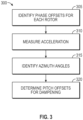
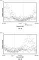
- a controller can use different phase offsets for each rotor when calculating pitch offsets for performing in-plane vibration damping. Using simulations, a controller can perform a phase offset sweep to identify the phase offset value that yields optimized dampening for each rotor.
- the movement of the center of the tower 105 from the axis 130A to the axis 130B causes the displacement 125.
- This displacement 125 results in respective displacements of the rotors 160.
- the side-to-side motion 150 of the tower 105 (which is primarily a lateral or horizontal motion) results in angled motion of the rotors 160 which is illustrated by the trajectories 120. That is, the motion 150 causes the rotor 160B to have a trajectory 120B where the rotor 160B moves up and to the right as the tower 105 sways to the right and moves down and to the left when the tower 105 sways to the left.
- the rotor 160A has a trajectory 120A where the rotor 160A moves down and to the right as the tower 105 sways to the right and moves up and to the left when the tower 105 sways to the left. Accordingly, the trajectories 120A and 120B are different since the rotors 160 are disposed on opposite sides of the tower 105.
- Figure 1 illustrates the trajectories 120 as being primarily linear
- the trajectories 120 will have some curve due to the rotational displacement 125 of the tower 105.
- a significant part of the trajectories 120 is defined by a vertical displacement of the rotors which results in the trajectories 120 being angled relative to the ground surface. This vertical displacement is generally absent from a single rotor turbine where the rotor is disposed on top of the tower.
- the angles of the trajectories 120 can depend on the distance from the tower 105 to the rotors 160 and the height of the tower 105.
- Figure 1 illustrates a first harmonic of the MR turbine 100
- the turbine can vibrate (e.g., sway) at several different harmonics at the same time, e.g., a second harmonic, third harmonic, etc. which is described in more detail in Figure 9 .
- the MR turbine 100 illustrates only two rotors 160, but the MR turbine 100 can include any number of rotors.
- the tower 105 could extend higher so that another set of rotors can be disposed on arms that are above the rotors 160 illustrated in Figure 1 .
- the MR turbine 100 can have rotors disposed on the tower in addition to the rotors 160 disposed on the ends of the arms 110.
- a third rotor could be disposed at the top of the tower 105 (e.g., between the rotors 160A and 160B).
- the dampener 215A generates pitch offsets 220A which are used to control the pitch actuators 205A of the rotor 160A while the dampener 215B generates pitch offsets 220B used to control the pitch actuators 205B of the rotor 160B.
- the dampeners 215 use signals from the sensors 207 to generate the pitch offsets 220.
- the dampener 215 can use a phase offset corresponding to the rotors 160 as well as the azimuth angles of the blades in the rotor planes to determine the pitch offsets 220.
- control system 1100 can be used on multiple rotors (where two instances of the control system 1100 are used for each rotor), in another embodiment, the control system 1100 may be used to perform in-plane vibration damping for multiple harmonics only on a single rotor in a MR turbine.
Landscapes
- Engineering & Computer Science (AREA)
- Life Sciences & Earth Sciences (AREA)
- Sustainable Development (AREA)
- Sustainable Energy (AREA)
- Chemical & Material Sciences (AREA)
- Combustion & Propulsion (AREA)
- Mechanical Engineering (AREA)
- General Engineering & Computer Science (AREA)
- Physics & Mathematics (AREA)
- Fluid Mechanics (AREA)
- Wind Motors (AREA)
Claims (14)
- Windkraftanlage (100) mit mehreren Rotoren (MR), umfassend:eine Turmstruktur (105),zumindest zwei Rotoranordnungen, welche von der Turmstruktur (105) getragen werden, wobei jede von den Rotoranordnungen eine Vielzahl von Blättern (170) umfasst;einen Sensor (207), welcher nahe einer ersten Rotoranordnung der zumindest zwei Rotoranordnungen angeordnet ist, und konfiguriert ist, um ein Signal (615, 705, 805, 810) zu erzeugen, welches einer Bewegung innerhalb der Ebene in einer Rotorebene der ersten Rotoranordnung der zumindest zwei Rotoranordnungen entspricht;einen zweiten Sensor (207), welcher nahe einer zweiten Rotoranordnung der zumindest zwei Rotoranordnungen angeordnet ist, und konfiguriert ist, um ein zweites Signal (615, 705, 805, 810) zu erzeugen, welches einer Bewegung innerhalb der Ebene in einer Rotorebene der zweiten Rotoranordnung entspricht, wobei das Signal (615, 705, 805, 810) und das zweite Signal (615, 705, 805, 810) mit zumindest einem verknüpft sind von: einer Lateralbeschleunigung und einer Vertikalbeschleunigung der ersten und zweiten Rotoranordnung; undeine Steuereinheit (210), die konfiguriert ist, um:das Signal (615, 705, 805, 810), welches der Bewegung innerhalb der Ebene in der Rotorebene der ersten Rotoranordnung entspricht, und das zweite Signal (615, 705, 805, 810), welches der Bewegung innerhalb der Ebene in der Rotorebene der zweiten Rotoranordnung entspricht, zu empfangen,einen ersten Phasenversatz (605, 805), welcher der ersten Rotoranordnung entspricht, und einen zweiten Phasenversatz (605, 805), welcher der zweiten Rotoranordnung entspricht, zu empfangen, wobei der erste und zweite Phasenversatz konstante Werte sind,das Signal (615, 705, 805, 810) und den ersten Phasenversatz (605, 805) als Eingabe für eine Rotationsfunktion (620) zu verwenden, um Blattwinkelversätze (635, 710, 820) zum Steuern von Blattwinkeln der Vielzahl von Blättern (170) der ersten Rotoranordnung zu bestimmen, um eine Kraft innerhalb der Ebene in der Form einer rotierenden oder einer oszillierenden Kraft in der Rotorebene der ersten Rotoranordnung zu erzeugen, sodass eine Phase der Kraft innerhalb der Ebene von einer Bewegungsbahn (120A) der ersten Rotoranordnung abhängt, welche durch die Bewegung innerhalb der Ebene veranlasst wird, wobei die Bewegungsbahn (120A) der ersten Rotoranordnung sowohl eine laterale Verschiebung als auch eine vertikale Verschiebung umfasst, unddas zweite Signal (615, 705, 805, 810) und den zweiten Phasenversatz (605, 805) als Eingabe für eine Rotationsfunktion (620) zu verwenden, um zweite Blattwinkelversätze (635, 710, 820) zum Steuern von Blattwinkeln der Vielzahl von Blättern (170) der zweiten Rotoranordnung zu bestimmen, um eine Kraft innerhalb der Ebene in der Form einer rotierenden oder einer oszillierenden Kraft in der Rotorebene der zweiten Rotoranordnung zu erzeugen, sodass eine Phase der Kraft innerhalb der Ebene von einer Bewegungsbahn (120B) der zweiten Rotoranordnung abhängt, welche durch die Bewegung innerhalb der Ebene veranlasst wird, wobei sich die Bewegungsbahn (120B) der zweiten Rotoranordnung von der Bewegungsbahn (120A) der ersten Rotoranordnung unterscheidet und sowohl eine laterale Verschiebung als auch eine vertikale Verschiebung umfasst.
- MR-Windkraftanlage (100) nach Anspruch 1, wobei die Blattwinkel für die erste Rotoranordnung dazu führen, dass die Kraft innerhalb der Ebene in der Rotorebene der ersten Rotoranordnung einen Phasenversatz in Bezug auf die Kraft innerhalb der Ebene in der zweiten Rotoranordnung aufweist, welche durch die Blattwinkel für die zweite Rotoranordnung veranlasst wird.
- MR-Windkraftanlage (100) nach Anspruch 1, wobei der erste und zweite Phasenversatz (605, 805) unterschiedliche, konstante Werte sind.
- MR-Windkraftanlage (100) nach Anspruch 1, wobei der erste und zweite Phasenversatz (605, 805) der gleiche, konstante Wert sind, und wobei die Steuereinheit (210) die Blattwinkelversätze (635, 710, 820) für die erste Rotoranordnung und die zweiten Blattwinkelversätze (635, 710, 820) für die zweite Rotoranordnung basierend auf einer Lateralbeschleunigung und einer Vertikalbeschleunigung der ersten und zweiten Rotoranordnung bestimmt.
- MR-Windkraftanlage (100) nach einem der vorstehenden Ansprüche, wobei die Steuereinheit (210) konfiguriert ist, um:eine erste Turmfrequenz einer ersten Oberschwingung der Turmstruktur (105) und eine zweite Turmfrequenz einer zweiten Oberschwingung der Turmstruktur (105) zu empfangen,wobei die Blattwinkelversätze (635, 710, 820) der ersten Rotoranordnung abgeleitet werden, um einer durch die ersten und zweiten Turmfrequenzen veranlassten Seitwärtsbewegung entgegenzuwirken, wobei die Seitwärtsbewegung im Wesentlichen senkrecht zu einer Aufwindrichtung verläuft.
- MR-Windkraftanlage (100) nach einem der vorstehenden Ansprüche, wobei die Steuereinheit (210) konfiguriert ist, um Azimutwinkel der Vielzahl von Blättern (170) zu empfangen, welche mit der ersten Rotoranordnung verbunden sind, und die empfangenen Azimutwinkel als Eingabe für die Rotationsfunktion (620) zu verwenden, um die Blattwinkelversätze (635, 710, 820) basierend auf den Azimutwinkeln zu bestimmen.
- MR-Windkraftanlage (100) nach Anspruch 1, wobei die Steuereinheit (210) konfiguriert ist, um Blattwinkelwerte für die Vielzahl von Blättern (170) einer zweiten Rotoranordnung der zumindest zwei Rotoranordnungen zu erzeugen, ohne eine Seitwärtsbewegung der Turmstruktur (105) zu berücksichtigen, welche im Wesentlichen senkrecht zu einer Aufwindrichtung ist, wobei die Kraft innerhalb der Ebene die Seitwärtsbewegung dämpft.
- MR-Windkraftanlage (100) nach einem der vorstehenden Ansprüche, wobei die erste Rotoranordnung auf einem ersten Arm (110A) angeordnet ist, welcher sich aus der Turmstruktur (105) in eine erste Richtung erstreckt, und eine zweite Rotoranordnung der zumindest zwei Rotoranordnungen auf einem zweiten Arm (110B) angeordnet ist, welcher sich aus der Turmstruktur (105) in eine zweite Richtung entgegengesetzt zur ersten Richtung erstreckt.
- MR-Windkraftanlage (100) nach einem der Ansprüche 1-7, wobei die Turmstruktur (105) zwei Trägerelemente umfasst, welche in zwei unterschiedlichen nicht senkrechten Winkeln in Bezug auf eine Bodenoberfläche gebildet sind, wobei die erste Rotoranordnung auf einem ersten von den beiden Trägerelementen angeordnet ist, und eine zweite Rotoranordnung der zumindest zwei Rotoranordnungen auf einem zweiten von den beiden Trägerelementen angeordnet ist.
- Verfahren zum Betreiben einer Windkraftanlage (100), umfassend zumindest zwei Rotoranordnungen, welche von der Turmstruktur (105) getragen werden, wobei jede der Rotoranordnungen eine Vielzahl von Blättern (170) umfasst, wobei das Verfahren umfasst:Empfangen eines Signals (615, 705, 805, 810), welches einer Bewegung innerhalb der Ebene in einer Rotorebene einer ersten Rotoranordnung der zumindest zwei Rotoranordnungen entspricht;Empfangen eines zweiten Signals (615, 705, 805, 810), welches einer Bewegung innerhalb der Ebene in einer Rotorebene einer zweiten Rotoranordnung entspricht, wobei das Signal (615, 705, 805, 810) und das zweite Signal (615, 705, 805, 810) mit zumindest einem verknüpft sind von: einer Lateralbeschleunigung und einer Vertikalbeschleunigung der ersten und zweiten Rotoranordnung;Empfangen eines ersten Phasenversatzes (605, 805), welcher der ersten Rotoranordnung entspricht, und eines zweiten Phasenversatzes (605, 805), welcher der zweiten Rotoranordnung entspricht, wobei der erste und zweite Phasenversatz konstante Werte sind,Verwenden des Signals (615, 705, 805, 810) und des ersten Phasenversatzes (605, 805) als Eingabe für eine Rotationsfunktion (620), zum Bestimmen von Blattwinkelversätzen (635, 710, 820) zum Steuern von Blattwinkeln der Vielzahl von Blättern (170) der ersten Rotoranordnung, um eine Kraft innerhalb der Ebene in der Form einer rotierenden oder einer oszillierenden Kraft in der Rotorebene der ersten Rotoranordnung zu erzeugen, sodass eine Phase der Kraft innerhalb der Ebene von einer Bewegungsbahn (120A) der ersten Rotoranordnung abhängt, welche durch die Bewegung innerhalb der Ebene veranlasst wird, wobei die Bewegungsbahn (120A) der ersten Rotoranordnung sowohl eine laterale Verschiebung als auch eine vertikale Verschiebung umfasst, undVerwenden des zweiten Signals (615, 705, 805, 810) und des zweiten Phasenversatzes (605, 805) als Eingabe für eine Rotationsfunktion (620), zum Bestimmen von zweiten Blattwinkelversätzen (635, 710, 820) zum Steuern von Blattwinkeln der Vielzahl von Blättern (170) der zweiten Rotoranordnung, um eine Kraft innerhalb der Ebene in der Form einer rotierenden oder einer oszillierenden Kraft in der Rotorebene der zweiten Rotoranordnung zu erzeugen, sodass eine Phase der Kraft innerhalb der Ebene von einer Bewegungsbahn (120B) der zweiten Rotoranordnung abhängt, welche durch die Bewegung innerhalb der Ebene veranlasst wird, wobei sich die Bewegungsbahn (120B) der zweiten Rotoranordnung von der Bewegungsbahn (120A) der ersten Rotoranordnung unterscheidet und sowohl eine laterale Verschiebung als auch eine vertikale Verschiebung umfasst.
- Verfahren nach Anspruch 10, wobei die Blattwinkel für die erste Rotoranordnung dazu führen, dass die Kraft innerhalb der Ebene in der Rotorebene der ersten Rotoranordnung einen Phasenversatz in Bezug auf die Kraft innerhalb der Ebene in der zweiten Rotoranordnung aufweist, welche durch die zweiten Blattwinkel für die zweite Rotoranordnung veranlasst wird.
- Verfahren nach Anspruch 10 oder 11, wobei der erste und zweite Phasenversatz (605, 805) unterschiedliche, konstante Werte sind.
- Verfahren nach Anspruch 10 oder 11, wobei der erste und zweite Phasenversatz (605, 805) der gleiche, konstante Wert sind, und wobei die Steuereinheit (210) die Blattwinkelversätze (635, 710, 820) für die erste Rotoranordnung und die zweiten Blattwinkelversätze (635, 710, 820) für die zweite Rotoranordnung basierend auf einer Lateralbeschleunigung und einer Vertikalbeschleunigung der ersten und zweiten Rotoranordnung bestimmt.
- Nichtflüchtiges computerlesbares Speichermedium, das einen darin integrierten computerlesbaren Programmcode aufweist, wobei der computerlesbare Programmcode konfiguriert ist, um das Verfahren nach einem der Ansprüche 10 bis 13 durchzuführen, wenn der Code durch einen Computer ausgeführt wird.
Applications Claiming Priority (2)
| Application Number | Priority Date | Filing Date | Title |
|---|---|---|---|
| DKPA202070026 | 2020-01-13 | ||
| PCT/DK2021/050007 WO2021143990A1 (en) | 2020-01-13 | 2021-01-12 | Damping of in-plane vibrations in multi-rotor structures |
Publications (3)
| Publication Number | Publication Date |
|---|---|
| EP4090845A1 EP4090845A1 (de) | 2022-11-23 |
| EP4090845B1 true EP4090845B1 (de) | 2024-07-03 |
| EP4090845C0 EP4090845C0 (de) | 2024-07-03 |
Family
ID=74191459
Family Applications (1)
| Application Number | Title | Priority Date | Filing Date |
|---|---|---|---|
| EP21700819.2A Active EP4090845B1 (de) | 2020-01-13 | 2021-01-12 | Dämpfen von schwingungen in der ebene von mehrrotorenstrukturen |
Country Status (3)
| Country | Link |
|---|---|
| US (1) | US11841005B2 (de) |
| EP (1) | EP4090845B1 (de) |
| WO (1) | WO2021143990A1 (de) |
Families Citing this family (2)
| Publication number | Priority date | Publication date | Assignee | Title |
|---|---|---|---|---|
| WO2021121501A1 (en) * | 2019-12-20 | 2021-06-24 | Vestas Wind Systems A/S | A method and a device for dampening movement in a multiple rotor wind turbine located at sea |
| WO2021143990A1 (en) | 2020-01-13 | 2021-07-22 | Vestas Wind Systems A/S | Damping of in-plane vibrations in multi-rotor structures |
Family Cites Families (9)
| Publication number | Priority date | Publication date | Assignee | Title |
|---|---|---|---|---|
| WO2016128004A1 (en) | 2015-02-12 | 2016-08-18 | Vestas Wind Systems A/S | Control system for damping structural vibrations of a wind turbine system having multiple rotors |
| ES2865194T3 (es) | 2016-02-24 | 2021-10-15 | Vestas Wind Sys As | Amortiguación de una oscilación de torre de turbina eólica |
| ES2858591T3 (es) * | 2016-02-26 | 2021-09-30 | Vestas Wind Sys As | Sistema de aerogenerador con múltiples rotores |
| CN109563809B (zh) | 2016-05-26 | 2020-10-27 | 维斯塔斯风力系统集团公司 | 在停机期间具有改善的稳定性的风力涡轮机系统 |
| PL3504425T3 (pl) | 2016-10-28 | 2022-12-27 | Siemens Gamesa Renewable Energy A/S | Tłumienie oscylacji wieży turbiny wiatrowej |
| WO2019042515A1 (en) | 2017-09-04 | 2019-03-07 | Vestas Wind Systems A/S | TORSION VIBRATION DAMPING IN A MULTI-ROTOR WIND TURBINE |
| CN112352097B (zh) | 2018-07-06 | 2024-06-14 | 维斯塔斯风力系统集团公司 | 多转子风力涡轮机振荡衰减 |
| EP3591218B1 (de) | 2018-07-06 | 2023-02-22 | Vestas Wind Systems A/S | Schwingungsbeschädigungsschutz für windturbine mit mehreren rotoren |
| WO2021143990A1 (en) | 2020-01-13 | 2021-07-22 | Vestas Wind Systems A/S | Damping of in-plane vibrations in multi-rotor structures |
-
2021
- 2021-01-12 WO PCT/DK2021/050007 patent/WO2021143990A1/en not_active Ceased
- 2021-01-12 EP EP21700819.2A patent/EP4090845B1/de active Active
- 2021-01-12 US US17/758,653 patent/US11841005B2/en active Active
Also Published As
| Publication number | Publication date |
|---|---|
| US20230035973A1 (en) | 2023-02-02 |
| EP4090845A1 (de) | 2022-11-23 |
| WO2021143990A1 (en) | 2021-07-22 |
| EP4090845C0 (de) | 2024-07-03 |
| US11841005B2 (en) | 2023-12-12 |
Similar Documents
| Publication | Publication Date | Title |
|---|---|---|
| US10590912B2 (en) | Counteracting tower oscillations of an idling wind turbine | |
| EP3504425B1 (de) | Dämpfung von windturbinenturmschwingungen | |
| US20120257967A1 (en) | Method and controller for generating a blade pitch angle control signal and wind turbine comprising the controller | |
| KR101741268B1 (ko) | 풍력 터빈 설비의 파도 에너지 추출 | |
| US11572865B2 (en) | Method and system for controlling a wind turbine to reduce nacelle vibration | |
| US11668283B2 (en) | Wind turbine method for detection and control of whirling oscillations | |
| WO2018171852A1 (en) | System and method to manage torsional oscillation of a wind turbine tower | |
| EP3167185A1 (de) | Aktive förderung von windturbinenturmschwankungen | |
| CN108061007A (zh) | 阻尼风力涡轮机的机械振荡 | |
| US11841005B2 (en) | Damping of in-plane vibrations in multi-rotor structures | |
| WO2019042515A1 (en) | TORSION VIBRATION DAMPING IN A MULTI-ROTOR WIND TURBINE | |
| WO2023072355A1 (en) | Whirling mode control of a wind turbine based on tower measurements | |
| JP2019094886A (ja) | 浮体式洋上風力発電装置 | |
| EP4455477A1 (de) | Aktive dämpfung für eine offshore-windturbine im leerlauf | |
| US20230272772A1 (en) | Controlling a floating wind turbine at critical frequencies | |
| CN111219294B (zh) | 风致振动的主动偏航缓解 | |
| WO2023084012A1 (en) | Actively damping vibrations in wind turbines | |
| EP4720507A1 (de) | Windturbinenantriebsstrangsteuerung auf basis der gondelrollgeschwindigkeit | |
| Tong | Control of large offshore wind turbines. |
Legal Events
| Date | Code | Title | Description |
|---|---|---|---|
| STAA | Information on the status of an ep patent application or granted ep patent |
Free format text: STATUS: UNKNOWN |
|
| STAA | Information on the status of an ep patent application or granted ep patent |
Free format text: STATUS: THE INTERNATIONAL PUBLICATION HAS BEEN MADE |
|
| PUAI | Public reference made under article 153(3) epc to a published international application that has entered the european phase |
Free format text: ORIGINAL CODE: 0009012 |
|
| STAA | Information on the status of an ep patent application or granted ep patent |
Free format text: STATUS: REQUEST FOR EXAMINATION WAS MADE |
|
| 17P | Request for examination filed |
Effective date: 20220809 |
|
| AK | Designated contracting states |
Kind code of ref document: A1 Designated state(s): AL AT BE BG CH CY CZ DE DK EE ES FI FR GB GR HR HU IE IS IT LI LT LU LV MC MK MT NL NO PL PT RO RS SE SI SK SM TR |
|
| DAV | Request for validation of the european patent (deleted) | ||
| DAX | Request for extension of the european patent (deleted) | ||
| REG | Reference to a national code |
Ref country code: DE Ref legal event code: R079 Free format text: PREVIOUS MAIN CLASS: F03D0001020000 Ipc: F03D0007020000 Ref document number: 602021015128 Country of ref document: DE |
|
| GRAP | Despatch of communication of intention to grant a patent |
Free format text: ORIGINAL CODE: EPIDOSNIGR1 |
|
| STAA | Information on the status of an ep patent application or granted ep patent |
Free format text: STATUS: GRANT OF PATENT IS INTENDED |
|
| RIC1 | Information provided on ipc code assigned before grant |
Ipc: F03D 1/02 20060101ALI20240213BHEP Ipc: F03D 7/02 20060101AFI20240213BHEP |
|
| INTG | Intention to grant announced |
Effective date: 20240314 |
|
| GRAS | Grant fee paid |
Free format text: ORIGINAL CODE: EPIDOSNIGR3 |
|
| GRAA | (expected) grant |
Free format text: ORIGINAL CODE: 0009210 |
|
| STAA | Information on the status of an ep patent application or granted ep patent |
Free format text: STATUS: THE PATENT HAS BEEN GRANTED |
|
| AK | Designated contracting states |
Kind code of ref document: B1 Designated state(s): AL AT BE BG CH CY CZ DE DK EE ES FI FR GB GR HR HU IE IS IT LI LT LU LV MC MK MT NL NO PL PT RO RS SE SI SK SM TR |
|
| REG | Reference to a national code |
Ref country code: CH Ref legal event code: EP |
|
| REG | Reference to a national code |
Ref country code: DE Ref legal event code: R096 Ref document number: 602021015128 Country of ref document: DE |
|
| U01 | Request for unitary effect filed |
Effective date: 20240703 |
|
| U07 | Unitary effect registered |
Designated state(s): AT BE BG DE DK EE FI FR IT LT LU LV MT NL PT SE SI Effective date: 20240709 |
|
| PG25 | Lapsed in a contracting state [announced via postgrant information from national office to epo] |
Ref country code: NO Free format text: LAPSE BECAUSE OF FAILURE TO SUBMIT A TRANSLATION OF THE DESCRIPTION OR TO PAY THE FEE WITHIN THE PRESCRIBED TIME-LIMIT Effective date: 20241003 |
|
| PG25 | Lapsed in a contracting state [announced via postgrant information from national office to epo] |
Ref country code: GR Free format text: LAPSE BECAUSE OF FAILURE TO SUBMIT A TRANSLATION OF THE DESCRIPTION OR TO PAY THE FEE WITHIN THE PRESCRIBED TIME-LIMIT Effective date: 20241004 Ref country code: PL Free format text: LAPSE BECAUSE OF FAILURE TO SUBMIT A TRANSLATION OF THE DESCRIPTION OR TO PAY THE FEE WITHIN THE PRESCRIBED TIME-LIMIT Effective date: 20240703 |
|
| PG25 | Lapsed in a contracting state [announced via postgrant information from national office to epo] |
Ref country code: IS Free format text: LAPSE BECAUSE OF FAILURE TO SUBMIT A TRANSLATION OF THE DESCRIPTION OR TO PAY THE FEE WITHIN THE PRESCRIBED TIME-LIMIT Effective date: 20241103 |
|
| PG25 | Lapsed in a contracting state [announced via postgrant information from national office to epo] |
Ref country code: HR Free format text: LAPSE BECAUSE OF FAILURE TO SUBMIT A TRANSLATION OF THE DESCRIPTION OR TO PAY THE FEE WITHIN THE PRESCRIBED TIME-LIMIT Effective date: 20240703 Ref country code: CZ Free format text: LAPSE BECAUSE OF FAILURE TO SUBMIT A TRANSLATION OF THE DESCRIPTION OR TO PAY THE FEE WITHIN THE PRESCRIBED TIME-LIMIT Effective date: 20240703 |
|
| PG25 | Lapsed in a contracting state [announced via postgrant information from national office to epo] |
Ref country code: RS Free format text: LAPSE BECAUSE OF FAILURE TO SUBMIT A TRANSLATION OF THE DESCRIPTION OR TO PAY THE FEE WITHIN THE PRESCRIBED TIME-LIMIT Effective date: 20241003 Ref country code: ES Free format text: LAPSE BECAUSE OF FAILURE TO SUBMIT A TRANSLATION OF THE DESCRIPTION OR TO PAY THE FEE WITHIN THE PRESCRIBED TIME-LIMIT Effective date: 20240703 |
|
| PG25 | Lapsed in a contracting state [announced via postgrant information from national office to epo] |
Ref country code: RS Free format text: LAPSE BECAUSE OF FAILURE TO SUBMIT A TRANSLATION OF THE DESCRIPTION OR TO PAY THE FEE WITHIN THE PRESCRIBED TIME-LIMIT Effective date: 20241003 Ref country code: PL Free format text: LAPSE BECAUSE OF FAILURE TO SUBMIT A TRANSLATION OF THE DESCRIPTION OR TO PAY THE FEE WITHIN THE PRESCRIBED TIME-LIMIT Effective date: 20240703 Ref country code: NO Free format text: LAPSE BECAUSE OF FAILURE TO SUBMIT A TRANSLATION OF THE DESCRIPTION OR TO PAY THE FEE WITHIN THE PRESCRIBED TIME-LIMIT Effective date: 20241003 Ref country code: IS Free format text: LAPSE BECAUSE OF FAILURE TO SUBMIT A TRANSLATION OF THE DESCRIPTION OR TO PAY THE FEE WITHIN THE PRESCRIBED TIME-LIMIT Effective date: 20241103 Ref country code: HR Free format text: LAPSE BECAUSE OF FAILURE TO SUBMIT A TRANSLATION OF THE DESCRIPTION OR TO PAY THE FEE WITHIN THE PRESCRIBED TIME-LIMIT Effective date: 20240703 Ref country code: GR Free format text: LAPSE BECAUSE OF FAILURE TO SUBMIT A TRANSLATION OF THE DESCRIPTION OR TO PAY THE FEE WITHIN THE PRESCRIBED TIME-LIMIT Effective date: 20241004 Ref country code: ES Free format text: LAPSE BECAUSE OF FAILURE TO SUBMIT A TRANSLATION OF THE DESCRIPTION OR TO PAY THE FEE WITHIN THE PRESCRIBED TIME-LIMIT Effective date: 20240703 Ref country code: CZ Free format text: LAPSE BECAUSE OF FAILURE TO SUBMIT A TRANSLATION OF THE DESCRIPTION OR TO PAY THE FEE WITHIN THE PRESCRIBED TIME-LIMIT Effective date: 20240703 |
|
| U20 | Renewal fee for the european patent with unitary effect paid |
Year of fee payment: 5 Effective date: 20250127 |
|
| PG25 | Lapsed in a contracting state [announced via postgrant information from national office to epo] |
Ref country code: SM Free format text: LAPSE BECAUSE OF FAILURE TO SUBMIT A TRANSLATION OF THE DESCRIPTION OR TO PAY THE FEE WITHIN THE PRESCRIBED TIME-LIMIT Effective date: 20240703 |
|
| PG25 | Lapsed in a contracting state [announced via postgrant information from national office to epo] |
Ref country code: SK Free format text: LAPSE BECAUSE OF FAILURE TO SUBMIT A TRANSLATION OF THE DESCRIPTION OR TO PAY THE FEE WITHIN THE PRESCRIBED TIME-LIMIT Effective date: 20240703 |
|
| PLBE | No opposition filed within time limit |
Free format text: ORIGINAL CODE: 0009261 |
|
| STAA | Information on the status of an ep patent application or granted ep patent |
Free format text: STATUS: NO OPPOSITION FILED WITHIN TIME LIMIT |
|
| 26N | No opposition filed |
Effective date: 20250404 |
|
| REG | Reference to a national code |
Ref country code: CH Ref legal event code: PL |
|
| PG25 | Lapsed in a contracting state [announced via postgrant information from national office to epo] |
Ref country code: MC Free format text: LAPSE BECAUSE OF FAILURE TO SUBMIT A TRANSLATION OF THE DESCRIPTION OR TO PAY THE FEE WITHIN THE PRESCRIBED TIME-LIMIT Effective date: 20240703 |
|
| GBPC | Gb: european patent ceased through non-payment of renewal fee |
Effective date: 20250112 |
|
| PG25 | Lapsed in a contracting state [announced via postgrant information from national office to epo] |
Ref country code: GB Free format text: LAPSE BECAUSE OF NON-PAYMENT OF DUE FEES Effective date: 20250112 |
|
| PG25 | Lapsed in a contracting state [announced via postgrant information from national office to epo] |
Ref country code: CH Free format text: LAPSE BECAUSE OF NON-PAYMENT OF DUE FEES Effective date: 20250131 |
|
| PG25 | Lapsed in a contracting state [announced via postgrant information from national office to epo] |
Ref country code: IE Free format text: LAPSE BECAUSE OF NON-PAYMENT OF DUE FEES Effective date: 20250112 |
|
| U20 | Renewal fee for the european patent with unitary effect paid |
Year of fee payment: 6 Effective date: 20260126 |
|
| PG25 | Lapsed in a contracting state [announced via postgrant information from national office to epo] |
Ref country code: RO Free format text: LAPSE BECAUSE OF FAILURE TO SUBMIT A TRANSLATION OF THE DESCRIPTION OR TO PAY THE FEE WITHIN THE PRESCRIBED TIME-LIMIT Effective date: 20240703 |