EP4090894B1 - Assemblage de valve pour un conduit d'air - Google Patents
Assemblage de valve pour un conduit d'air Download PDFInfo
- Publication number
- EP4090894B1 EP4090894B1 EP21706702.4A EP21706702A EP4090894B1 EP 4090894 B1 EP4090894 B1 EP 4090894B1 EP 21706702 A EP21706702 A EP 21706702A EP 4090894 B1 EP4090894 B1 EP 4090894B1
- Authority
- EP
- European Patent Office
- Prior art keywords
- valve
- valve assembly
- rotor part
- air duct
- outer rotor
- Prior art date
- Legal status (The legal status is an assumption and is not a legal conclusion. Google has not performed a legal analysis and makes no representation as to the accuracy of the status listed.)
- Active
Links
Images



Classifications
-
- F—MECHANICAL ENGINEERING; LIGHTING; HEATING; WEAPONS; BLASTING
- F24—HEATING; RANGES; VENTILATING
- F24F—AIR-CONDITIONING; AIR-HUMIDIFICATION; VENTILATION; USE OF AIR CURRENTS FOR SCREENING
- F24F13/00—Details common to, or for air-conditioning, air-humidification, ventilation or use of air currents for screening
- F24F13/08—Air-flow control members, e.g. louvres, grilles, flaps or guide plates
- F24F13/10—Air-flow control members, e.g. louvres, grilles, flaps or guide plates movable, e.g. dampers
- F24F13/14—Air-flow control members, e.g. louvres, grilles, flaps or guide plates movable, e.g. dampers built up of tilting members, e.g. louvre
- F24F13/1486—Air-flow control members, e.g. louvres, grilles, flaps or guide plates movable, e.g. dampers built up of tilting members, e.g. louvre characterised by bearings, pivots or hinges
-
- F—MECHANICAL ENGINEERING; LIGHTING; HEATING; WEAPONS; BLASTING
- F24—HEATING; RANGES; VENTILATING
- F24F—AIR-CONDITIONING; AIR-HUMIDIFICATION; VENTILATION; USE OF AIR CURRENTS FOR SCREENING
- F24F13/00—Details common to, or for air-conditioning, air-humidification, ventilation or use of air currents for screening
- F24F13/08—Air-flow control members, e.g. louvres, grilles, flaps or guide plates
- F24F13/10—Air-flow control members, e.g. louvres, grilles, flaps or guide plates movable, e.g. dampers
- F24F13/12—Air-flow control members, e.g. louvres, grilles, flaps or guide plates movable, e.g. dampers built up of sliding members
-
- F—MECHANICAL ENGINEERING; LIGHTING; HEATING; WEAPONS; BLASTING
- F21—LIGHTING
- F21V—FUNCTIONAL FEATURES OR DETAILS OF LIGHTING DEVICES OR SYSTEMS THEREOF; STRUCTURAL COMBINATIONS OF LIGHTING DEVICES WITH OTHER ARTICLES, NOT OTHERWISE PROVIDED FOR
- F21V33/00—Structural combinations of lighting devices with other articles, not otherwise provided for
- F21V33/0088—Ventilating systems
-
- F—MECHANICAL ENGINEERING; LIGHTING; HEATING; WEAPONS; BLASTING
- F24—HEATING; RANGES; VENTILATING
- F24F—AIR-CONDITIONING; AIR-HUMIDIFICATION; VENTILATION; USE OF AIR CURRENTS FOR SCREENING
- F24F13/00—Details common to, or for air-conditioning, air-humidification, ventilation or use of air currents for screening
- F24F13/02—Ducting arrangements
- F24F13/06—Outlets for directing or distributing air into rooms or spaces, e.g. ceiling air diffuser
- F24F13/078—Outlets for directing or distributing air into rooms or spaces, e.g. ceiling air diffuser combined with lighting fixtures
-
- F—MECHANICAL ENGINEERING; LIGHTING; HEATING; WEAPONS; BLASTING
- F24—HEATING; RANGES; VENTILATING
- F24F—AIR-CONDITIONING; AIR-HUMIDIFICATION; VENTILATION; USE OF AIR CURRENTS FOR SCREENING
- F24F13/00—Details common to, or for air-conditioning, air-humidification, ventilation or use of air currents for screening
- F24F13/08—Air-flow control members, e.g. louvres, grilles, flaps or guide plates
- F24F13/10—Air-flow control members, e.g. louvres, grilles, flaps or guide plates movable, e.g. dampers
- F24F13/14—Air-flow control members, e.g. louvres, grilles, flaps or guide plates movable, e.g. dampers built up of tilting members, e.g. louvre
- F24F13/1426—Air-flow control members, e.g. louvres, grilles, flaps or guide plates movable, e.g. dampers built up of tilting members, e.g. louvre characterised by actuating means
- F24F2013/1473—Air-flow control members, e.g. louvres, grilles, flaps or guide plates movable, e.g. dampers built up of tilting members, e.g. louvre characterised by actuating means with cams or levers
-
- F—MECHANICAL ENGINEERING; LIGHTING; HEATING; WEAPONS; BLASTING
- F24—HEATING; RANGES; VENTILATING
- F24F—AIR-CONDITIONING; AIR-HUMIDIFICATION; VENTILATION; USE OF AIR CURRENTS FOR SCREENING
- F24F2221/00—Details or features not otherwise provided for
- F24F2221/02—Details or features not otherwise provided for combined with lighting fixtures
Definitions
- the present invention relates to a valve assembly for use in an air duct for ventilating a building.
- the assembly includes a controllable valve having flow control means for controlling the flow of air through the valve and rotatable adjustment means for adjusting the position of flow control means of the valve.
- the assembly further includes fastening means for rotatably attaching an outer surface of the adjustable valve to the air duct.
- the present invention further relates to a mechanical ventilation system for forced or unforced ventilation of a home, office building and the like, comprising at least one air duct and a ventilation device connected to said air duct in which such a valve assembly is provided.
- buildings have air ducts that provide passageways for the exchange, ventilation, circulation and/or movement of air through the surfaces (e.g. walls and ceilings) of the building.
- Buildings may have ventilation systems, which draw in "fresh” air from outside the building and expel “exhaust” air from inside the building. Fresh air can be drawn into a building or exhaust air can be expelled from a building through one or more air ducts.
- Some buildings contain other systems and/or devices, such as air-conditioning systems, heating systems and bathroom fans, that use air ducts to provide passageways for air to flow through the surfaces of buildings.
- an air duct is associated with devices such as ventilation nozzles and/or ventilation grilles to direct air flows out of the ventilation ducts.
- Some of these devices contain valves for adjusting the flow. This makes it possible to regulate the air flow through the device.
- valves are usually rigidly connected to the surrounding structures. This may have the disadvantage that the installation is more difficult, but especially that the cleaning, repair or replacement of the valve (or elements located behind the valve) is more difficult.
- Existing devices may also have the disadvantage that manipulation of the device may cause undesirable dislocation of the valve or damage by manipulation with a large amount of force.
- Document EP 2 492 606 A1 discloses a valve assembly for use in an air duct for ventilation comprising an adjustable valve with flow control means and rotary adjusting means.
- An object of the invention is to provide a valve assembly of the aforementioned type which does not exhibit at least one of the disadvantages of the state of the art.
- a further object of the invention may be to provide a valve assembly of the aforementioned type in or on a ventilation duct.
- An object of the invention may be to provide a valve assembly of the foregoing type having means of adjustment which enable a user to control a valve of the valve assembly in the ventilation duct by rotation and an aiming and rotating component, provided with or connected to the means of adjustment, which, on the one hand, allows manipulation of the means of adjustment and, on the other hand, can be aimed independently of the position of the means of adjustment.
- a further object of the invention may be to provide a valve assembly which includes fastening means to allow a user to fix the valve assembly in or to a ventilation duct, adjusting means to allow a user to control a valve of the valve assembly in the ventilation duct and locking means to allow a user to lock the position of the valve against unwanted manipulation.
- a further object of the invention may be to prevent damage to the valve assembly in the locked position by manipulation with a large amount of force.
- a further object of the invention may be to provide the valve assembly as easily, non-destructively removable or replaceable.
- the invention in a first aspect of the invention, which may occur in combination with the other aspects and embodiments of the invention described herein, the invention includes a valve assembly for use in an air duct for ventilation of a building.
- the assembly includes a controllable valve with flow control means for controlling the flow of air through the valve and rotatable adjustment means for adjusting the position of flow control means of the valve.
- the assembly further includes fasteners for rotatably attaching an outer surface of the adjustable valve to the air duct in a manner that permits rotation between the adjustable valve and the air duct.
- to mechanically connect the controllable valve - directly or indirectly - to the inner surface of the air duct Preferably by means of a non-permanent connection, i.e. a connection which can be removed or dismantled without damaging the connection components.
- the rotational resistance related to the fasteners is smaller than the rotational resistance related to the adjusting means, relative rotation between the adjusting means and displacement of the flow control means are prevented even when a sufficient amount of force is applied to overcome the resistance related to the fasteners. This maintains the position of flow control means of the valve when manipulating the means of adjustment.
- a first embodiment which may occur in combination with the other aspects and embodiments of the invention described herein, relates to a aforementioned valve assembly, wherein the rotational resistance related to the adjustment means is adjustable between a first predetermined value in the unlocked configuration of the valve assembly and a second predetermined value in the locked configuration of the valve assembly, wherein the first predetermined value is smaller than the second predetermined value.
- a second embodiment which may occur in conjunction with the other aspects and embodiments of the invention described herein, relates to a aforementioned valve assembly, wherein, in the locked configuration of the valve assembly, the valve assembly further includes locking means provided to prevent adjustment of the position of the flow control means of the valve.
- a third embodiment which may occur in combination with the other aspects and embodiments of the invention described herein, relates to a aforementioned valve assembly, in which the locking means are removably provided.
- a fourth embodiment which may occur in conjunction with the other aspects and embodiments of the invention described herein, relates to a aforementioned valve assembly, wherein the fasteners include an annular coil spring arranged to mechanically hold the adjustable valve.
- the valve assembly further comprises a housing with a housing outer surface adapted to be attached to the air duct and an opposite housing inner surface for receiving the fasteners so as to attach the adjustable valve and the housing to each other with a predetermined rotation resistance.
- a sixth embodiment which may occur in combination with the other aspects and embodiments of the invention described herein, relates to a aforementioned valve assembly, wherein the position of the flow control means of the valve is manually adjustable in discrete steps.
- the adjustable valve includes: a stator having an annular stator member adapted to be attached to the air channel; an outer rotor part provided in the space defined by the annular stator member; and an inner rotor member enclosed in the space between the stator and the outer rotor part, and the inner rotor member is connected to the stator and the outer rotor part.
- the valve is adjusted to adjust the axial position of the inner rotor part relative to the outer rotor part such that the cross section of an air passage between the outer rotor part and the inner rotor part is changed by rotating the outer rotor part.
- the rotational resistance related to the connecting means is related to the rotational resistance between the stator and the inner and/or outer rotor part.
- the invention in a second aspect of the invention, which may occur in combination with the other aspects and embodiments of the invention described herein, the invention includes a mechanical ventilation system comprising a ventilation device connected to an air duct in which a valve assembly as described above is provided.
- the air duct may have a predominantly circular cross-section with preferably a diameter of 80, 100, 125 or 160 mm.
- the inner surface of the air duct and the outer housing side may have a similar cross-section, for example a mainly circular cross-section, or different cross-sections, for example a mainly circular cross-section and a mainly polygonal cross-section.
- the invention includes a building comprising a ventilation system as described above.
- top, bottom, over, under and the like in the description and the claims are used for illustrative purposes and not necessarily to describe relative positions. The terms so used are interchangeable under appropriate circumstances and the embodiments of the invention described herein may be used in orientations other than those described or illustrated herein.
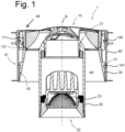
- FIGS 1 and 2 show a valve assembly 1 for use in an air duct, or at an end of the air duct, of a mechanical or natural ventilation system of a dwelling or the like.
- the valve assembly 1 shown includes an annular housing 40 in which a valve 10 of the valve assembly 1 is mechanically retained via an annular coil spring 140.
- the valve assembly 1 further includes a fixture portion 20, 23 which is connected to the valve 10 and extends from a side of the valve 10 arranged to be directed towards a chamber of the dwelling into which the air duct terminates when the housing 40 is inserted into the air duct.
- the housing 40 has an outer housing side 41 that is adapted to be connected to and attached to or near the air duct 2.
- the housing may include one or more attachment elements that are provided in or behind a finish layer of the housing, for example a plaster layer, and one or more sealing elements to connect the portion of the housing extending into the air duct to the air duct 2 and to seal the space between the housing 40 and the air duct 2 in a substantially airtight manner.
- the sealing elements are located near the end of the housing to be turned towards the air duct.
- the fastening elements and the sealing elements may be located at opposite ends of the housing or at the same end of the housing.
- the housing 40 further has an inner housing side 42, opposite the outer housing side 41, which is adapted to be connected to the valve 10.
- the valve 10 includes an adjustable valve with adjustment means and flow control means for controlling the flow or pressure of air flowing through the housing 40 based on the position of the adjustment means.
- valve assembly 1 may include an annular guide element 30 to conduct air between the to the chamber end of the housing 40 and the to the chamber end of the assembly.
- the guide element 30 may be mechanically retained via an annular coil spring 141.
- the annular guide element 30 may extend in the axial direction A from the annular element 136 of the stator 130 to the chamber-facing edge of the housing 40.
- the annular guide element 30 may extend in the axial direction A beyond the space-facing edge of the housing 40.
- the annular guide element 30 extends further in the radial direction such that the visual indications of the annular element 136, preferably the entire annular element 136, are hidden from the view of the user.
- the inner surface of the annular guide element 30 is adapted to provide a good, desired airflow between the space-facing edge of the housing 40 and the space-facing side of the stator.
- the annular coil springs 140, 141 are adapted to be inserted into an annular slot 31, 134 of the valve 10 or the guide element 30 to secure (lock and hold) the respective part to the housing 40. This allows the valve 10 and the guide element 30 to be removed from the housing 40 to allow for easy cleaning of the valve assembly 1 and the air channel 2.
- the coil springs may be, for example, compression springs and/or tilted helical springs.
- the coil spring 140, 141 produces a radial or axial force so that the coil spring 31, 140 remains in contact with the mating surface and can compensate for large adjustment tolerances, alignment, and surface irregularities.
- the rotational resistance between the valve 10, the annular coil spring 140 and the housing 40 will be greater than the rotational resistance of the adjustment means when the valve is connected to the air duct.
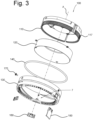
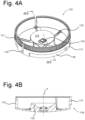
- FIGS 3 , 4A-B , 5A-B and 6A-B show a valve 100 for attaching the luminaire body 20 to the housing 40 and for controlling the flow or pressure of air passing through the housing 40.
- the valve 100 includes a stationary portion 130, also referred to as a stator, adapted to be stationary connected to the housing 40 or the air channel, and a rotatable assembly 110, 120, also referred to as a rotor, rotatably connected to said stator 130.
- the rotatable assembly includes an inner rotor part 120 and an outer rotor part 110.
- the outer rotor part 110 is formed by an annular outer rotor element 111 connected to a central bowl-shaped element 113 via a number of spacers 115, preferably positioned symmetrically around the bowl-shaped element 113, at the upper end of the outer rotor element 111.
- the outer rotor element 111 includes a number of parallel slots 112 extending from the lower end of the annular element 111 arranged to face the stator 130, and said slots 112 are preferably positioned symmetrically around the bowl-shaped element 113.
- the number of projections 125 of the inner rotor part 120 and the number of parallel slots 112 of the outer rotor part 110 are positioned at corresponding angular positions in the angular direction, preferably arranged symmetrically around the respective annular member. As such, when the inner rotor part 120 is inserted into the outer rotor part 110, each protrusion 125 extends through a respective slot 112 to a widened portion of the protrusion 127 provided outside the outer rotor part 110, wherein the width of the widened portion of the protrusion 127 is greater than the width of the respective slot 112.
- the protrusion 125 will prevent movement of the inner and outer rotor elements 111, 121 relative to each other in a plane perpendicular to the axial direction A, e.g., by translation in radial direction or by rotation in angular direction.
- the stator 130 further includes openings 138a, 138b, of a locking mechanism and a ratchet mechanism respectively, which extend axially from the lower end of the stator element 131 to permit insertion of a complementary element by a user when installed and extend radially across the inner surface 132 to permit interaction between the complementary element and the outer surface of the outer rotor element 111.
- the valve assembly By inserting locking means 150 into the opening 138a, the valve assembly is moved from an unlocked configuration to a locked configuration and the rotational resistance related to the adjustment means is adjusted from a first predetermined value to a second, larger predetermined value.
- the second value is predetermined such that the adjustment means, in the locked configuration, experiences more rotational resistance than the rotational resistance between the valve 10, the annular coil spring 140 and the housing 40.
- the stator element 131 further includes a number of recessed holes 139 on its outer surface to receive a respective screw or the like 170 extending into a respective recessed surface 116 of the outer rotor element 111 to mechanically hold the outer rotor part 110, and thereby also the inner rotor part 120, within the annular stator element 131, i.e. in the space defined by the annular stator member 131 and the lower ring 136.
- the screw 170 and recessed surfaces 116 further limit the rotational movement of the outer rotor part 110 in the angular direction.
Landscapes
- Engineering & Computer Science (AREA)
- General Engineering & Computer Science (AREA)
- Chemical & Material Sciences (AREA)
- Combustion & Propulsion (AREA)
- Mechanical Engineering (AREA)
- Air-Flow Control Members (AREA)
- Arrangement Of Elements, Cooling, Sealing, Or The Like Of Lighting Devices (AREA)
- Multiple-Way Valves (AREA)
- Electrically Driven Valve-Operating Means (AREA)
- Duct Arrangements (AREA)
Claims (11)
- Ensemble vanne (1) pour une utilisation dans un conduit d'air pour la ventilation d'un bâtiment, comprenant :une vanne (10 ; 100) réglable comportant un moyen (113, 126) de contrôle d'écoulement pour contrôler l'écoulement d'air à travers la vanne et un moyen (112, 114, 125, 135) de réglage rotatif pour régler la position du moyen (113, 126) de contrôle d'écoulement de la vanne (10 ; 100), et caractérisé en ce que l'ensemble vanne comprendun moyen (140) de fixation pour fixer une surface externe (133) de la vanne (10 ; 100) réglable rotative avec le conduit d'air,l'ensemble vanne étant en outre caractérisé en ce que dans une configuration déverrouillée de l'ensemble vanne, la résistance de rotation associée au moyen de fixation est supérieure à la résistance de rotation associée au moyen de réglage afin de permettre le réglage de la vanne par rotation du moyen de réglage lorsque la vanne est raccordée au conduit d'air ; etdans lequel, dans une configuration verrouillée de l'ensemble vanne, la résistance de rotation associée au moyen de fixation est inférieure à la résistance de rotation associée au moyen de réglage afin de verrouiller le réglage de la vanne lorsque la vanne est raccordée rotative au conduit d'air.
- Ensemble vanne (1) selon la revendication 1, comprenant en outre un corps (20) orientable et rotatif adapté pour être raccordé au moyen de réglage de la vanne réglable de telle manière que la position du moyen de contrôle d'écoulement de la vanne (10 ; 100) peut être réglée manuellement par l'intermédiaire d'une rotation axiale du corps (20) dans la configuration déverrouillée de l'ensemble vanne et que la position du corps (20) de luminaire par rapport à la vanne réglable peut être réglée manuellement dans la configuration verrouillée de l'ensemble vanne.
- Ensemble vanne (1) selon la revendication 2, dans lequel le corps est formé par un corps électrique (20) adapté pour raccorder une source d'alimentation à un dispositif de consommation électrique.
- Ensemble vanne (1) selon l'une quelconque des revendications précédentes, dans lequel la résistance de rotation liée au moyen de réglage est réglable entre une première valeur prédéterminée dans la configuration déverrouillée de l'ensemble vanne et une seconde valeur prédéterminée dans la configuration verrouillée de l'ensemble vanne, la première valeur prédéterminée étant inférieure à la seconde valeur prédéterminée.
- Ensemble vanne (1) selon l'une quelconque des revendications précédentes, dans lequel, dans la configuration verrouillée de l'ensemble vanne, l'ensemble vanne comprend en outre un moyen de verrouillage (150) fourni pour empêcher le réglage de la position du moyen de contrôle d'écoulement de la vanne (10 ; 100).
- Ensemble vanne (1) selon la revendication 5, dans lequel le moyen de verrouillage (150) est amovible.
- Ensemble vanne (1) selon l'une quelconque des revendications précédentes, le moyen de fixation comprenant un ressort hélicoïdal annulaire (140) agencé pour maintenir mécaniquement la vanne réglable (10, 100).
- Ensemble vanne (1) selon l'une quelconque des revendications précédentes, comprenant en outre :
un logement (40) comportant un côté (41) de logement externe adapté pour être fixé au conduit d'air et un côté (42) de logement interne opposé pour recevoir le moyen (140) de fixation afin de fixer la vanne réglable (10, 100) et le logement (40) l'un à l'autre avec une résistance de rotation prédéterminée. - Ensemble vanne (1) selon l'une quelconque des revendications précédentes, selon lequel la position du moyen de contrôle d'écoulement de la vanne (10 ; 100) est réglable manuellement en étapes discrètes.
- Ensemble vanne (1) selon l'une quelconque des revendications précédentes, comprenant la vanne (10 ; 100) réglable :un stator (130) comportant un élément (131) de stator annulaire adapté pour être fixé au conduit d'air ;une partie (110) de rotor externe fournie dans l'espace défini par l'élément (131) de stator annulaire ; etune partie (120) de rotor interne enfermée dans l'espace entre le stator (130) et la partie (110) de rotor externe, et la partie (120) de rotor interne est raccordée au stator (130) et à la partie (110) de rotor externe,dans lequel la vanne (100) est réglée pour changer la position axiale de la partie (120) de rotor interne par rapport à la partie (110) de rotor externe de telle manière que la section transversale d'un passage d'air entre la partie (110) de rotor externe et la partie (120) de rotor interne est changée par rotation de la partie (110) de rotor externe,où la résistance de rotation liée au moyen de fixation est égale à la résistance de rotation entre le stator (130) et la partie (120) de rotor interne et/ou externe.
- Système de ventilation mécanique comprenant un conduit d'air et un dispositif de ventilation raccordé au conduit d'air, dans lequel un ensemble vanne (1) selon l'une quelconque des revendications précédentes est fourni.
Applications Claiming Priority (4)
| Application Number | Priority Date | Filing Date | Title |
|---|---|---|---|
| EP20152161.4A EP3851757B1 (fr) | 2020-01-16 | 2020-01-16 | Soupape réglable pour un conduit d'air dans un système de ventilation |
| NL2024689A NL2024689B1 (en) | 2020-01-16 | 2020-01-17 | Adjustable valve assembly for an air duct in a ventilation system |
| BE20205691A BE1028676B1 (nl) | 2020-01-16 | 2020-10-06 | In of aan een ventilatiekanaal voorzienbare elektrische inrichting |
| PCT/IB2021/050350 WO2021144775A1 (fr) | 2020-01-16 | 2021-01-18 | Ensemble de vanne pour un conduit d'air |
Publications (3)
| Publication Number | Publication Date |
|---|---|
| EP4090894A1 EP4090894A1 (fr) | 2022-11-23 |
| EP4090894C0 EP4090894C0 (fr) | 2023-12-20 |
| EP4090894B1 true EP4090894B1 (fr) | 2023-12-20 |
Family
ID=74669206
Family Applications (2)
| Application Number | Title | Priority Date | Filing Date |
|---|---|---|---|
| EP21706702.4A Active EP4090894B1 (fr) | 2020-01-16 | 2021-01-18 | Assemblage de valve pour un conduit d'air |
| EP21706701.6A Pending EP4090893A1 (fr) | 2020-01-16 | 2021-01-18 | Sortie d'air avec appareil électrique |
Family Applications After (1)
| Application Number | Title | Priority Date | Filing Date |
|---|---|---|---|
| EP21706701.6A Pending EP4090893A1 (fr) | 2020-01-16 | 2021-01-18 | Sortie d'air avec appareil électrique |
Country Status (6)
| Country | Link |
|---|---|
| US (1) | US12313285B2 (fr) |
| EP (2) | EP4090894B1 (fr) |
| BE (1) | BE1027970B1 (fr) |
| CA (1) | CA3169037A1 (fr) |
| NL (2) | NL2027339B1 (fr) |
| WO (2) | WO2021144774A1 (fr) |
Families Citing this family (3)
| Publication number | Priority date | Publication date | Assignee | Title |
|---|---|---|---|---|
| BE1029732B1 (nl) * | 2021-09-07 | 2023-04-03 | Delta Light N V | Verlichtingssamenstel |
| WO2023025969A1 (fr) * | 2021-08-27 | 2023-03-02 | Delta Light N.V. | Ensemble pour système d'appareil d'éclairage |
| US20250290658A1 (en) * | 2024-03-14 | 2025-09-18 | Air Distribution Technologies Ip, Llc | Integrated lighting system for diffuser of an hvac system |
Family Cites Families (18)
| Publication number | Priority date | Publication date | Assignee | Title |
|---|---|---|---|---|
| US3299797A (en) * | 1964-09-02 | 1967-01-24 | John P Dry | Combined air diffuser and lighting fixture |
| DE7523491U (de) | 1975-07-23 | 1977-02-17 | Siemens Ag, 1000 Berlin Und 8000 Muenchen | Abluftleuchte mit verstellbarem tellerventil |
| FR2331755A1 (fr) | 1975-11-17 | 1977-06-10 | Strulik Wilhelm | Luminaire distributeur d'air |
| ES2212719B1 (es) * | 2002-05-22 | 2005-10-01 | Cata Electrodomesticos, S.L | Extractor de aire de apertura automatica. |
| AU2005205768B2 (en) * | 2004-09-06 | 2007-01-18 | Rickard Air Diffusion (Proprietary) Limited | Air diffuser |
| EP2080959A1 (fr) * | 2008-01-15 | 2009-07-22 | Vahik Petrossian | Verrouillage de positionnement d'amortisseur |
| US9335061B2 (en) * | 2008-05-30 | 2016-05-10 | Airius Ip Holdings, Llc | Columnar air moving devices, systems and methods |
| KR100995670B1 (ko) * | 2008-12-11 | 2010-11-19 | 강남필터 주식회사 | 조명장치가 내장된 에어 디퓨져 |
| GB2480300B (en) * | 2010-05-13 | 2015-03-18 | John Morehead | Ventilating cowl |
| CN102588307A (zh) * | 2011-01-06 | 2012-07-18 | 广东松下环境系统有限公司 | 带照明顶棚埋入式换气扇 |
| PL2492606T3 (pl) * | 2011-02-28 | 2017-12-29 | Acticon Ab | Urządzenie do regulacji przepływu powietrza |
| KR101369290B1 (ko) * | 2012-04-17 | 2014-03-04 | 강성실 | 조명이 구비된 환기구 |
| KR20150140066A (ko) * | 2014-06-05 | 2015-12-15 | 강성실 | Led 조명등이 구비된 욕실용 환기장치 |
| NL2013030B1 (en) * | 2014-06-19 | 2016-07-06 | Toptech Int N V | Building with ventilation system and terminal. |
| KR101851061B1 (ko) * | 2016-05-25 | 2018-04-20 | 주식회사 비엘케이 | 조명기구 일체형 디퓨져 |
| CN107830618B (zh) * | 2017-10-26 | 2023-11-21 | 珠海格力电器股份有限公司 | 导风装置及应用其的空调器 |
| GB2582259A (en) * | 2019-03-01 | 2020-09-23 | Sleep Safe Systems Ltd | Ventilation fixture |
| CN111131024A (zh) | 2019-12-09 | 2020-05-08 | 盛科网络(苏州)有限公司 | 聚合链路的处理方法及装置 |
-
2021
- 2021-01-18 WO PCT/IB2021/050349 patent/WO2021144774A1/fr not_active Ceased
- 2021-01-18 NL NL2027339A patent/NL2027339B1/nl active
- 2021-01-18 CA CA3169037A patent/CA3169037A1/fr active Pending
- 2021-01-18 EP EP21706702.4A patent/EP4090894B1/fr active Active
- 2021-01-18 WO PCT/IB2021/050350 patent/WO2021144775A1/fr not_active Ceased
- 2021-01-18 NL NL2027341A patent/NL2027341B1/nl active
- 2021-01-18 EP EP21706701.6A patent/EP4090893A1/fr active Pending
- 2021-01-18 BE BE20215030A patent/BE1027970B1/nl active IP Right Grant
- 2021-01-18 US US17/758,950 patent/US12313285B2/en active Active
Also Published As
| Publication number | Publication date |
|---|---|
| EP4090894A1 (fr) | 2022-11-23 |
| WO2021144774A1 (fr) | 2021-07-22 |
| NL2027339A (nl) | 2021-08-31 |
| US20230341146A1 (en) | 2023-10-26 |
| NL2027341B1 (nl) | 2023-09-11 |
| BE1027970B1 (nl) | 2022-02-16 |
| WO2021144775A1 (fr) | 2021-07-22 |
| CA3169037A1 (fr) | 2021-07-22 |
| US12313285B2 (en) | 2025-05-27 |
| EP4090893A1 (fr) | 2022-11-23 |
| BE1027970A1 (nl) | 2021-08-02 |
| EP4090894C0 (fr) | 2023-12-20 |
| NL2027339B1 (nl) | 2023-09-13 |
| NL2027341A (nl) | 2021-08-31 |
Similar Documents
| Publication | Publication Date | Title |
|---|---|---|
| EP4090894B1 (fr) | Assemblage de valve pour un conduit d'air | |
| US10641506B2 (en) | Columnar air moving devices, systems and methods | |
| EP2492557B1 (fr) | Ensemble d'actionnement de soupape doté d'interconnexion sans outil | |
| US6527194B1 (en) | Flow control damper | |
| KR100957122B1 (ko) | 환기덕트의 디퓨저 | |
| US7108600B1 (en) | Air duct register | |
| BE1028676B1 (nl) | In of aan een ventilatiekanaal voorzienbare elektrische inrichting | |
| JP2009250552A (ja) | 換気グリル | |
| EP3851757B1 (fr) | Soupape réglable pour un conduit d'air dans un système de ventilation | |
| WO2022123517A1 (fr) | Ensemble pour conduit d'air dans un système de ventilation | |
| KR200414327Y1 (ko) | 디퓨저 | |
| WO2022074076A1 (fr) | Ensemble vanne pour conduit d'aération | |
| KR200359094Y1 (ko) | 에어컨 배관용 슬리브의 실내 노출구 커버 및 그 노출구커버를 체결하기 위한 실내 연결관 | |
| KR20170054358A (ko) | 환기시스템의 수동 댐퍼 | |
| KR20210096372A (ko) | 전동형 댐퍼 | |
| AU2011202374A1 (en) | Vent Assembly | |
| KR20160087406A (ko) | 환기시스템의 수동 댐퍼 | |
| KR20030005902A (ko) | 회전이 가능한 분리형 에어컨의 서비스 밸브 | |
| KR20160102376A (ko) | 환기시스템의 수동 댐퍼 |
Legal Events
| Date | Code | Title | Description |
|---|---|---|---|
| STAA | Information on the status of an ep patent application or granted ep patent |
Free format text: STATUS: UNKNOWN |
|
| STAA | Information on the status of an ep patent application or granted ep patent |
Free format text: STATUS: THE INTERNATIONAL PUBLICATION HAS BEEN MADE |
|
| PUAI | Public reference made under article 153(3) epc to a published international application that has entered the european phase |
Free format text: ORIGINAL CODE: 0009012 |
|
| STAA | Information on the status of an ep patent application or granted ep patent |
Free format text: STATUS: REQUEST FOR EXAMINATION WAS MADE |
|
| 17P | Request for examination filed |
Effective date: 20220809 |
|
| AK | Designated contracting states |
Kind code of ref document: A1 Designated state(s): AL AT BE BG CH CY CZ DE DK EE ES FI FR GB GR HR HU IE IS IT LI LT LU LV MC MK MT NL NO PL PT RO RS SE SI SK SM TR |
|
| DAV | Request for validation of the european patent (deleted) | ||
| DAX | Request for extension of the european patent (deleted) | ||
| GRAP | Despatch of communication of intention to grant a patent |
Free format text: ORIGINAL CODE: EPIDOSNIGR1 |
|
| STAA | Information on the status of an ep patent application or granted ep patent |
Free format text: STATUS: GRANT OF PATENT IS INTENDED |
|
| INTG | Intention to grant announced |
Effective date: 20230714 |
|
| GRAS | Grant fee paid |
Free format text: ORIGINAL CODE: EPIDOSNIGR3 |
|
| GRAA | (expected) grant |
Free format text: ORIGINAL CODE: 0009210 |
|
| STAA | Information on the status of an ep patent application or granted ep patent |
Free format text: STATUS: THE PATENT HAS BEEN GRANTED |
|
| AK | Designated contracting states |
Kind code of ref document: B1 Designated state(s): AL AT BE BG CH CY CZ DE DK EE ES FI FR GB GR HR HU IE IS IT LI LT LU LV MC MK MT NL NO PL PT RO RS SE SI SK SM TR |
|
| REG | Reference to a national code |
Ref country code: GB Ref legal event code: FG4D |
|
| REG | Reference to a national code |
Ref country code: CH Ref legal event code: EP |
|
| REG | Reference to a national code |
Ref country code: DE Ref legal event code: R096 Ref document number: 602021007892 Country of ref document: DE |
|
| REG | Reference to a national code |
Ref country code: IE Ref legal event code: FG4D |
|
| U01 | Request for unitary effect filed |
Effective date: 20240116 |
|
| U07 | Unitary effect registered |
Designated state(s): AT BE BG DE DK EE FI FR IT LT LU LV MT NL PT SE SI Effective date: 20240125 |
|
| PG25 | Lapsed in a contracting state [announced via postgrant information from national office to epo] |
Ref country code: GR Free format text: LAPSE BECAUSE OF FAILURE TO SUBMIT A TRANSLATION OF THE DESCRIPTION OR TO PAY THE FEE WITHIN THE PRESCRIBED TIME-LIMIT Effective date: 20240321 |
|
| PG25 | Lapsed in a contracting state [announced via postgrant information from national office to epo] |
Ref country code: ES Free format text: LAPSE BECAUSE OF FAILURE TO SUBMIT A TRANSLATION OF THE DESCRIPTION OR TO PAY THE FEE WITHIN THE PRESCRIBED TIME-LIMIT Effective date: 20231220 |
|
| PG25 | Lapsed in a contracting state [announced via postgrant information from national office to epo] |
Ref country code: GR Free format text: LAPSE BECAUSE OF FAILURE TO SUBMIT A TRANSLATION OF THE DESCRIPTION OR TO PAY THE FEE WITHIN THE PRESCRIBED TIME-LIMIT Effective date: 20240321 Ref country code: ES Free format text: LAPSE BECAUSE OF FAILURE TO SUBMIT A TRANSLATION OF THE DESCRIPTION OR TO PAY THE FEE WITHIN THE PRESCRIBED TIME-LIMIT Effective date: 20231220 |
|
| U20 | Renewal fee for the european patent with unitary effect paid |
Year of fee payment: 4 Effective date: 20240325 |
|
| PG25 | Lapsed in a contracting state [announced via postgrant information from national office to epo] |
Ref country code: RS Free format text: LAPSE BECAUSE OF FAILURE TO SUBMIT A TRANSLATION OF THE DESCRIPTION OR TO PAY THE FEE WITHIN THE PRESCRIBED TIME-LIMIT Effective date: 20231220 Ref country code: NO Free format text: LAPSE BECAUSE OF FAILURE TO SUBMIT A TRANSLATION OF THE DESCRIPTION OR TO PAY THE FEE WITHIN THE PRESCRIBED TIME-LIMIT Effective date: 20240320 Ref country code: HR Free format text: LAPSE BECAUSE OF FAILURE TO SUBMIT A TRANSLATION OF THE DESCRIPTION OR TO PAY THE FEE WITHIN THE PRESCRIBED TIME-LIMIT Effective date: 20231220 |
|
| PG25 | Lapsed in a contracting state [announced via postgrant information from national office to epo] |
Ref country code: IS Free format text: LAPSE BECAUSE OF FAILURE TO SUBMIT A TRANSLATION OF THE DESCRIPTION OR TO PAY THE FEE WITHIN THE PRESCRIBED TIME-LIMIT Effective date: 20240420 |
|
| PG25 | Lapsed in a contracting state [announced via postgrant information from national office to epo] |
Ref country code: CZ Free format text: LAPSE BECAUSE OF FAILURE TO SUBMIT A TRANSLATION OF THE DESCRIPTION OR TO PAY THE FEE WITHIN THE PRESCRIBED TIME-LIMIT Effective date: 20231220 |
|
| PG25 | Lapsed in a contracting state [announced via postgrant information from national office to epo] |
Ref country code: SK Free format text: LAPSE BECAUSE OF FAILURE TO SUBMIT A TRANSLATION OF THE DESCRIPTION OR TO PAY THE FEE WITHIN THE PRESCRIBED TIME-LIMIT Effective date: 20231220 |
|
| PG25 | Lapsed in a contracting state [announced via postgrant information from national office to epo] |
Ref country code: SM Free format text: LAPSE BECAUSE OF FAILURE TO SUBMIT A TRANSLATION OF THE DESCRIPTION OR TO PAY THE FEE WITHIN THE PRESCRIBED TIME-LIMIT Effective date: 20231220 Ref country code: SK Free format text: LAPSE BECAUSE OF FAILURE TO SUBMIT A TRANSLATION OF THE DESCRIPTION OR TO PAY THE FEE WITHIN THE PRESCRIBED TIME-LIMIT Effective date: 20231220 Ref country code: RO Free format text: LAPSE BECAUSE OF FAILURE TO SUBMIT A TRANSLATION OF THE DESCRIPTION OR TO PAY THE FEE WITHIN THE PRESCRIBED TIME-LIMIT Effective date: 20231220 Ref country code: IS Free format text: LAPSE BECAUSE OF FAILURE TO SUBMIT A TRANSLATION OF THE DESCRIPTION OR TO PAY THE FEE WITHIN THE PRESCRIBED TIME-LIMIT Effective date: 20240420 Ref country code: CZ Free format text: LAPSE BECAUSE OF FAILURE TO SUBMIT A TRANSLATION OF THE DESCRIPTION OR TO PAY THE FEE WITHIN THE PRESCRIBED TIME-LIMIT Effective date: 20231220 |
|
| PG25 | Lapsed in a contracting state [announced via postgrant information from national office to epo] |
Ref country code: PL Free format text: LAPSE BECAUSE OF FAILURE TO SUBMIT A TRANSLATION OF THE DESCRIPTION OR TO PAY THE FEE WITHIN THE PRESCRIBED TIME-LIMIT Effective date: 20231220 |
|
| PG25 | Lapsed in a contracting state [announced via postgrant information from national office to epo] |
Ref country code: PL Free format text: LAPSE BECAUSE OF FAILURE TO SUBMIT A TRANSLATION OF THE DESCRIPTION OR TO PAY THE FEE WITHIN THE PRESCRIBED TIME-LIMIT Effective date: 20231220 |
|
| REG | Reference to a national code |
Ref country code: CH Ref legal event code: PL |
|
| REG | Reference to a national code |
Ref country code: DE Ref legal event code: R097 Ref document number: 602021007892 Country of ref document: DE |
|
| PG25 | Lapsed in a contracting state [announced via postgrant information from national office to epo] |
Ref country code: MC Free format text: LAPSE BECAUSE OF FAILURE TO SUBMIT A TRANSLATION OF THE DESCRIPTION OR TO PAY THE FEE WITHIN THE PRESCRIBED TIME-LIMIT Effective date: 20231220 |
|
| PG25 | Lapsed in a contracting state [announced via postgrant information from national office to epo] |
Ref country code: CH Free format text: LAPSE BECAUSE OF NON-PAYMENT OF DUE FEES Effective date: 20240131 |
|
| PLBE | No opposition filed within time limit |
Free format text: ORIGINAL CODE: 0009261 |
|
| STAA | Information on the status of an ep patent application or granted ep patent |
Free format text: STATUS: NO OPPOSITION FILED WITHIN TIME LIMIT |
|
| PG25 | Lapsed in a contracting state [announced via postgrant information from national office to epo] |
Ref country code: CH Free format text: LAPSE BECAUSE OF NON-PAYMENT OF DUE FEES Effective date: 20240131 |
|
| 26N | No opposition filed |
Effective date: 20240923 |
|
| PG25 | Lapsed in a contracting state [announced via postgrant information from national office to epo] |
Ref country code: IE Free format text: LAPSE BECAUSE OF NON-PAYMENT OF DUE FEES Effective date: 20240118 |
|
| PG25 | Lapsed in a contracting state [announced via postgrant information from national office to epo] |
Ref country code: IE Free format text: LAPSE BECAUSE OF NON-PAYMENT OF DUE FEES Effective date: 20240118 |
|
| U20 | Renewal fee for the european patent with unitary effect paid |
Year of fee payment: 5 Effective date: 20250128 |
|
| PG25 | Lapsed in a contracting state [announced via postgrant information from national office to epo] |
Ref country code: CY Free format text: LAPSE BECAUSE OF FAILURE TO SUBMIT A TRANSLATION OF THE DESCRIPTION OR TO PAY THE FEE WITHIN THE PRESCRIBED TIME-LIMIT; INVALID AB INITIO Effective date: 20210118 |
|
| PG25 | Lapsed in a contracting state [announced via postgrant information from national office to epo] |
Ref country code: HU Free format text: LAPSE BECAUSE OF FAILURE TO SUBMIT A TRANSLATION OF THE DESCRIPTION OR TO PAY THE FEE WITHIN THE PRESCRIBED TIME-LIMIT; INVALID AB INITIO Effective date: 20210118 |
|
| GBPC | Gb: european patent ceased through non-payment of renewal fee |
Effective date: 20250118 |
|
| PG25 | Lapsed in a contracting state [announced via postgrant information from national office to epo] |
Ref country code: GB Free format text: LAPSE BECAUSE OF NON-PAYMENT OF DUE FEES Effective date: 20250118 |
|
| PG25 | Lapsed in a contracting state [announced via postgrant information from national office to epo] |
Ref country code: TR Free format text: LAPSE BECAUSE OF FAILURE TO SUBMIT A TRANSLATION OF THE DESCRIPTION OR TO PAY THE FEE WITHIN THE PRESCRIBED TIME-LIMIT Effective date: 20231220 |
|
| U20 | Renewal fee for the european patent with unitary effect paid |
Year of fee payment: 6 Effective date: 20260129 |