EP4090903B1 - Ensemble glissière pour arme à feu - Google Patents
Ensemble glissière pour arme à feu Download PDFInfo
- Publication number
- EP4090903B1 EP4090903B1 EP20880387.4A EP20880387A EP4090903B1 EP 4090903 B1 EP4090903 B1 EP 4090903B1 EP 20880387 A EP20880387 A EP 20880387A EP 4090903 B1 EP4090903 B1 EP 4090903B1
- Authority
- EP
- European Patent Office
- Prior art keywords
- slide
- assembly
- extractor
- mounting recess
- stop
- Prior art date
- Legal status (The legal status is an assumption and is not a legal conclusion. Google has not performed a legal analysis and makes no representation as to the accuracy of the status listed.)
- Active
Links
Images






Classifications
-
- F—MECHANICAL ENGINEERING; LIGHTING; HEATING; WEAPONS; BLASTING
- F41—WEAPONS
- F41A—FUNCTIONAL FEATURES OR DETAILS COMMON TO BOTH SMALLARMS AND ORDNANCE, e.g. CANNONS; MOUNTINGS FOR SMALLARMS OR ORDNANCE
- F41A3/00—Breech mechanisms, e.g. locks
- F41A3/12—Bolt action, i.e. the main breech opening movement being parallel to the barrel axis
- F41A3/14—Rigid bolt locks, i.e. having locking elements rigidly mounted on the bolt or bolt handle and on the barrel or breech-housing respectively
- F41A3/16—Rigid bolt locks, i.e. having locking elements rigidly mounted on the bolt or bolt handle and on the barrel or breech-housing respectively the locking elements effecting a rotary movement about the barrel axis, e.g. rotating cylinder bolt locks
- F41A3/26—Rigid bolt locks, i.e. having locking elements rigidly mounted on the bolt or bolt handle and on the barrel or breech-housing respectively the locking elements effecting a rotary movement about the barrel axis, e.g. rotating cylinder bolt locks semi-automatically or automatically operated, e.g. having a slidable bolt-carrier and a rotatable bolt
-
- F—MECHANICAL ENGINEERING; LIGHTING; HEATING; WEAPONS; BLASTING
- F41—WEAPONS
- F41A—FUNCTIONAL FEATURES OR DETAILS COMMON TO BOTH SMALLARMS AND ORDNANCE, e.g. CANNONS; MOUNTINGS FOR SMALLARMS OR ORDNANCE
- F41A15/00—Cartridge extractors, i.e. devices for pulling cartridges or cartridge cases at least partially out of the cartridge chamber; Cartridge ejectors, i.e. devices for throwing the extracted cartridges or cartridge cases free of the gun
- F41A15/12—Cartridge extractors, i.e. devices for pulling cartridges or cartridge cases at least partially out of the cartridge chamber; Cartridge ejectors, i.e. devices for throwing the extracted cartridges or cartridge cases free of the gun for bolt-action guns
- F41A15/14—Cartridge extractors, i.e. devices for pulling cartridges or cartridge cases at least partially out of the cartridge chamber; Cartridge ejectors, i.e. devices for throwing the extracted cartridges or cartridge cases free of the gun for bolt-action guns the ejector being mounted on or within the bolt; Extractors per se
-
- F—MECHANICAL ENGINEERING; LIGHTING; HEATING; WEAPONS; BLASTING
- F41—WEAPONS
- F41A—FUNCTIONAL FEATURES OR DETAILS COMMON TO BOTH SMALLARMS AND ORDNANCE, e.g. CANNONS; MOUNTINGS FOR SMALLARMS OR ORDNANCE
- F41A3/00—Breech mechanisms, e.g. locks
- F41A3/64—Mounting of breech-blocks; Accessories for breech-blocks or breech-block mountings
- F41A3/66—Breech housings or frames; Receivers
-
- F—MECHANICAL ENGINEERING; LIGHTING; HEATING; WEAPONS; BLASTING
- F41—WEAPONS
- F41G—WEAPON SIGHTS; AIMING
- F41G1/00—Sighting devices
- F41G1/30—Reflecting-sights specially adapted for smallarms or ordnance
-
- F—MECHANICAL ENGINEERING; LIGHTING; HEATING; WEAPONS; BLASTING
- F41—WEAPONS
- F41C—SMALLARMS, e.g. PISTOLS, RIFLES; ACCESSORIES THEREFOR
- F41C3/00—Pistols, e.g. revolvers
Definitions
- the exemplary embodiments of the subject disclosure relate generally to firearms and, more specifically, to a slide assembly for a firearm.
- a bright dot sight is particularly advantageous, as it operates to project, within a transparent viewfinder a virtual or holographic reticle or "dot" which, when superimposed on a target, tracks the hit trajectory of a fired bullet, regardless of the orientation of a user's eyes with respect to the handgun.
- the bright dot sight permits the user to focus most of his/her attention on the target, rather than on alignment of rear and forward iron sights for aiming the handgun.
- the bright dot sight also allows the user to more consistently discriminate between threat and nonthreat scenarios, reducing potential for misidentification and needless loss of life.
- the recoil force generated by a handgun can be substantial, particularly with respect to centerfire handgun calibers used for hunting, defense, and in the line of duty.
- forces created by the abrupt rearward movement of the slide upon firing, followed by a subsequent forward movement and closure of the slide under spring force are particularly damaging to mounting systems of early sights.
- Large and sturdy mounting systems were developed previously to address these issues, but they added undesirable bulk and weight that rendered them impractical for tactical and law enforcement use.
- the necessity for large mounting systems decreased only after advances in ruggedization and miniaturization of optic sights enabled them to better withstand the recoil forces of a violently reciprocating handgun slide.
- a handgun slide often requires substantial after-market modifications to accommodate today's advanced sights.
- Such modifications typically include milling a recess into the slide for receiving the sight and one or more threaded retaining holes into the bottom surface of the recess to receive threaded fasteners for affixing the sight to the slide.
- the recess is milled as deep as possible to streamline and lower the sight with respect to the slide to permit a conventional iron sight mounted to the front of the slide to be viewable through a transparent viewfinder of the sight, thereby permitting a user to aim the handgun in the event of sight malfunction.
- US2014230305 A1 , US2019331461 A1 and US2017059277 A1 disclose prior art ways for mounting a sight on a handgun.
- bosses provide additional stability and material for withstanding damaging shearing forces.
- mounting holes of different sights are sized and positioned differently, bosses may be milled into a slide to accommodate only one type/brand of sight having a particular pattern of mounting holes. This necessarily requires gun manufacturers and after-market gunsmiths to design numerous different milling specifications to accommodate numerous different gun/sight combinations. It also limits the ability to interchange sights, for example, when bosses milled into a handgun slide are not compatible with a desired sight.
- intermediate mounting plate positioned between the recess of the slide and the sight.
- Such a mounting plate features appropriately sized and located mounting holes for affixing multiple types/brands of sights.
- intermediate mounting plates allow for modularity, they limit the depth at which sights can be positioned relative to handgun slides. By-adding an additional component, intermediate plates also increase the probability of forming failure points within sight mounting systems.
- a slide assembly for a firearm according to Claim 1 a firearm according to Claim 9, and a method for modifying an original slide assembly of a firearm according to Claim 10.
- Preferred embodiments of the invention are defined in Claims 2 to 8 and Claims 11 to 14. In the following description, embodiments will be described. These embodiments fall within the scope of the present invention only if they are in accordance with Claims 1, 9 and 10.
- Various embodiments of the subject disclosure position (or adjust the position of) various internal components of the slide in order to reduce or eliminate interference between these components and fasteners used to affix a sight to the slide. In this manner, various embodiments of the subject disclosure permit formation of a deep recess within the slide for receiving the sight without need for bosses or other reinforcing structures. Various other embodiments provide the recess with multiple threaded hole patterns for accommodating multiple different types/brands of sights.
- range format is merely for convenience and brevity and should not be construed as an inflexible limitation on the scope of the subject disclosure. Accordingly, the description of a range should be considered to have specifically disclosed all the possible subranges as well as individual numerical values within that range. For example, description of a range such as from 1 to 6 should be considered to have specifically disclosed subranges such as from 1 to 3, from 1 to 4, from 1 to 5, from 2 to 4, from 2 to 6, from 3 to 6 etc., as well as individual numbers within that range, for example, 1, 2, 2.7, 3, 4, 5, 5.3, and 6. This applies regardless of the breadth of the range.
- Slide assembly 100 for a firearm (such as, for example, a handgun), in accordance with an exemplary embodiment of the subject disclosure.
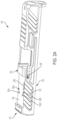
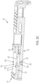
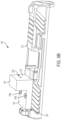
- Slide assembly 100 includes a slide 102, front and rear iron sights 128, 130 for permitting a user to aim the firearm in a conventional fashion, and slide components 250 positioned within slide 102, including firing assembly 205, extractor assembly 112 and firing pin safety 295.
- Slide assembly 100 is configured to be coupled to a firearm frame having other components (not shown) for forming a completed firearm.
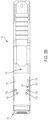
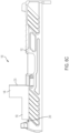
- Slide 102 includes a bottom side 126, a top side 106 provided at a proximal end 110 with a mounting recess 104 having one or more retaining holes 142 (a through d) for receiving an optic sight (as more fully described below) and a housing recess 108 positioned below the bottom surface of mounting recess 104 for receiving slide components 250.
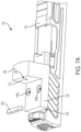
- Slide 102 also includes a blind stopper bore 255 extending into a lateral side 122 from mounting recess 104, a stop removal bore 260 extending from a bottom of blind stopper bore 255 to bottom side 126 of slide 102, and a tooling slot 265 extending from a top of blind stopper bore 255 along the bottom surface of mounting recess 104.
- mounting recess 104 is formed on slide 102 as a substantially rectangular recess, although it may assume other shapes including, for example and without limitation, substantially square, oval, polygonal, and/or circular shapes. In some embodiments, mounting recess 104 may be dispensed with entirely, in which case an optic sight may be mounted directly to a planar portion of top side 106 of slide 102 adjacent its proximal end 110.
- Firing assembly 205 includes a firing pin 210 at a proximal end 220 slidably positioned within spacer sleeves 215a, 215b and biased forwardly toward a distal end 232 of firing assembly 205 by pin spring 225 acting on spacer sleeve 215a.
- Firing assembly 205 also includes spring cups 230a, 230b attached to firing pin 210 to provide a backstop for pin spring 225.
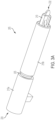
- Extractor assembly 112 includes proximal and distal ends 116, 114, an extractor 132 with a gripping end 235 mounted pivotally about a pivot end 245 within slide 102, a biasing member 136 (e.g., a spring) for urging a plunger 240 against extractor 132, a bearing 134 for providing a backstop for biasing member 136 and for limiting movement of plunger 240 against biasing member and toward proximal end 116 of extractor assembly 112, and a stop 138 for limiting movement of bearing 134 toward proximal end 110 of slide 102.
- a biasing member 136 e.g., a spring
- stop 138 is positioned entirely within stopper bore 255 of slide 102 approximately about a mid-portion 118 of mounting recess 104 such that an entirety of extractor assembly 112 is positioned within housing recess 108 below the front of mounting recess 104 (or further forward, in some embodiments), thereby leaving at least a rear region of housing recess 108 clear of any components of extractor assembly 112.
- stopper bore 255 may be placed in other orientations (e.g., horizontal, at an angle, etc.) or at other positions relative to mounting recess 104.
- stop 138 may be formed with screw threads or other features, and that various embodiments of the subject disclosure are not intended to be limited to specific structures used to form stop 138.
- extractor assembly 112 (without stop 138) is first properly positioned within housing recess 108.
- a user then inserts a tool (not shown) within tooling slot 265 to withdraw biasing member 136 and bearing 134 distally toward extractor 132.
- Stop 138 is then inserted fully within stopper bore 255 downwardly from the bottom of mounting recess 104, after which the tool is removed. Removal of the tool causes biasing member 136 to bias bearing 134 against the side of stop 138 and, in this manner, maintain stop 138 within stopper bore 255 via friction.
- Stop 138 is prevented from escaping upwardly via an installed optic sight (see below) or, alternatively, via a cover plate (not shown), which may be installed within mounting recess 104 of slide 102 in the event an optic sight is not installed.
- the user To remove extractor assembly 112 from slide 102, the user first removes the optic sight (or cover plate), after which he/she employs the tool to withdraw biasing member 136 again while simultaneously inserting a pin (not shown) into stop removal bore 260 from bottom side 126 of slide 102. This causes stop 138 to travel upwardly above the bottom surface of mounting recess 104, where it can be removed by hand. Once stop 138 is removed, the tool may be extracted and the remaining portions of extractor assembly 112 removed from housing recess 108 in a conventional manner.
- tooling slot 265 and stop removal bore 260 are provided to facilitate installation and removal of extractor assembly 112 from slide 102. It should be appreciated, however, that one or both of tooling slot 265 and stop removal bore 260 may be omitted, and that various embodiments of the subject disclosure are not intended to require either one. It should also be appreciated that various embodiments of the subject disclosure are not intended to require any structures for facilitating or assisting with installation and removal of extractor assembly 112 from slide 102.
- Firing assembly 205 and extractor assembly 112 operate together to fire a bullet and extract a spent cartridge casing from a barrel (not shown) of the firearm.
- a live cartridge (with a bullet) is positioned within the barrel such that gripping end 235 of extractor 132 engages a rim of the cartridge casing.
- firing pin 210 of firing assembly 205 is urged rapidly toward distal end 230 of firing assembly 205 to strike the cartridge, thereby causing the bullet of the cartridge to be fired through the barrel of the firearm.
- Optic sight 146 includes a viewfinder 270 operable to project a reflexive or holographic bright dot 280 and a base plate 150 having two mounting holes 275a, 275b sized to receive respective fasteners 144a, 144b for rigidly affixing optic sight 146 to slide 102 via retaining holes 142a, 142b.
- fasteners 144a, 144b and retaining holes 142a, 142b are threaded to permit optic sight 146 to be affixed to slide 102 using screw-like fasteners 144a, 144b.
- fasteners 144a, 144b and retaining holes 142a, 142b may be used, and that various embodiments of the subject disclosure are not intended to be limited to any particular structure or mechanism for affixing optic sight 146 to slide 102. It should also be appreciated that, although optic sight 146 is shown affixed to slide 102 using two fasteners 144a, 144b, any number of fasteners 144 can be employed, depending on the type/brand or design of optic sight 146.
- fasteners 144a, 144b can extend deep within slide 102 without interfering with extractor assembly 112 or other slide components 250. In this manner, fasteners 144a, 144b grip more material of slide 102 to provide a strong and rugged affixing ability without need for bosses and/or other reinforcing structures, though various embodiments of the subject disclosure do not preclude the use of bosses and/or other reinforcing structures. Positioning extractor assembly 112 in this manner also allows mounting recess 104 to be formed deeper into slide 102 to advantageously lower optic sight 146 for better coincidence of iron sights 128, 130 with bright dot 280 of optic sight 146.
- multiple different patterns of retaining holes 142 may be provided on the bottom surface of mounting recess 104 to accommodate multiple different types/brands of optic sights.
- the embodiments depicted in the Figures illustrate two sets of retaining holes 142 (i.e., retaining holes 142a, 142b and retaining holes 142c, 142d) for accommodating two different types/brands of optic sights, including optic sight 146.
- additional patterns of retaining holes 142 may be provided on the bottom surface of mounting recess 104 to expand compatibility of slide assembly 100 with other types/brands of optic sights.
- These additional patterns of retaining holes 142 may be provided during manufacture of slide 102 to create a "universal" optic sight mount, or alternatively may be formed into slide 102 after-market, for example, by a gunsmith.
- mounting recess 104 long enough longitudinally (i.e., between the proximal and distal ends of mounting recess 104) to accommodate optic sights 146 having different longitudinal lengths and mounting holes at different longitudinal positions.
- a gap 290 will form, for example, between the proximal end of mounting recess 104 and the proximal end of a mounted optic sight (see Figures 6b and 6c ).
- This gap 290 is not only unsightly, but it may also reduce support provided to the optic sight which, in turn, may lead to damage of the sight or sheering of fasteners 144a, 144b resulting from extreme forces produced by reciprocation of slide 102.
- various embodiments of the subject disclosure provide one or more keyed spacers 285 that may be positioned to fill gap 290 and provide additional support for the optic sight 146, for example, support for preventing optic sight 146 from twisting or otherwise moving with respect to slide 102 when installed (see Figures 7a and 7b ).
- support is improved by constructing keyed spacers 285 (or a combination of keyed spacers 285) to be slightly larger than gap 290, so that keyed spacers maintain frictional compression with optic sight 146 when installed.
- keyed spacers 285 may be constructed of a rubber-like material (or material having rubber-like qualities) and/or be coated in a rubber-like or similar material, although in other embodiments keyed spacers are constructed from a rigid material, such as, for example, metal or a rigid polymer.
- Mounting recess 104 may also be provided with texture or be coated with a rubberlike material to prevent movement, or twisting of an optic sight.
- keyed spacers 285 may be provided with lateral arms for cradling the left and right sides of optic sight 146. Keyed spacers 285 may also be provided with one or more cams having coupled screws, whereby tightening of the screws urges the cams against, the back of optic sight 146 to further improve the grip between keyed spacers 285 and optic sight 146. Keyed spacers 285 may also be provided with a textured surface to improve grip between keyed spacers 285 and optic sight 146. It should be appreciated that different sizes and numbers of spacers 285 may be provided to accommodate and fill different sized gaps 290. It should also be appreciated that similar spacers 285 may be provided to fill any gaps that may form between the distal end of mounting recess 104 and the distal end of the mounted optic sight, or at any other location within mounting recess 104.
- one or more annual bearings are inserted into each mounting hole 275 of optic sight 146.
- the annual bearings are designed to fit snugly within mounting holes 275 and to slidingly receive fasteners 144 for mounting optic sight 146 to slide 102.
- the annual bearings provide lateral support within mounting holes 275 to reduce movement and twisting of optic sight 146.
- Different annual bearings with different dimensions may be designed to accommodate multiple different types/brands or designs of optic sights.
- a retaining compound such as Loctite ® retaining compound
- the retaining compound cures and forms a bond between fasteners 144 and the inside surfaces of mounting holes 275, thereby improving support and minimizing (or eliminating) the chance of movement or twisting of optic sight 146 when mounted on slide 102.
- FIG. 8 there is seen a flow diagram 800 depicting a process for modifying an original slide assembly of a handgun, such as a Glock ® handgun, to produce slide assembly 100, in accordance with an exemplary embodiment of the subject disclosure.
- the process begins at step 801 and proceeds to step 805.
- an original extractor assembly (not shown) is removed from housing recess 108 of the original slide.
- Extractor assemblies of Glock ® handguns for example, include lengthened bearings that typically extend from the biasing member all the way to the slide's proximal back end, which acts as a support for the extractor assembly.
- step 810 mounting recess 104 is formed into top side 106 of the original slide for receiving an optic sight.
- step 815 stopper bore 255, stop removal bore 260 and tooling slot 265 are formed into the original slide.
- Retaining holes such as, for example, retaining holes 142a, 142b, 142c, 142d, are then formed into the slide at step 820, after which the process proceeds to step 825.
- extractor assembly 112 is inserted into housing recess 108 (see insertion procedure described above) to produce slide assembly 100.
- step 830 ends at step 830.
Landscapes
- Engineering & Computer Science (AREA)
- General Engineering & Computer Science (AREA)
- Physics & Mathematics (AREA)
- Optics & Photonics (AREA)
- Toys (AREA)
Claims (14)
- Ensemble glissière (100) destiné à une arme à feu comprenant :une glissière (102) ayant un côté supérieur (106), une extrémité proximale (110), un évidement de montage (104) autour du côté supérieur de la glissière, et un évidement de logement (108) autour de l'extrémité proximale de la glissière ; etun ensemble extracteur (112) monté à l'intérieur de l'évidement de logement (108), caractérisé en ce que :
l'ensemble extracteur comporte une extrémité distale (114) pour venir en prise avec une cartouche et une extrémité proximale (116) se terminant au niveau d'une position à proximité d'une partie médiane (118) de l'évidement de montage, l'ensemble extracteur comportant :un extracteur (132) ayant une extrémité distale pour venir en prise avec une cartouche et une extrémité proximale se terminant au niveau d'une position à proximité d'une extrémité distale de l'évidement de montage,un piston (240) s'étendant de manière proximale à partir de l'extracteur,un élément de sollicitation (136) sollicitant le piston de manière distale contre l'extracteur,un palier (134) fournissant une butée arrière pour l'élément de sollicitation et limitant le mouvement du piston par rapport à l'élément de sollicitation, etune butée (138) limitant le mouvement du palier. - Ensemble glissière selon la revendication 1, dans lequel l'extrémité proximale de l'ensemble extracteur se termine au niveau d'une position distale de la partie médiane de l'évidement de montage.
- Ensemble glissière selon les revendications 1 à 2, dans lequel la glissière comporte en outre un alésage d'arrêt (255), la butée de l'extracteur étant positionnée à l'intérieur de l'alésage d'arrêt, ou dans lequel la glissière comporte en outre une fente d'outillage (265) sur une surface inférieure de l'évidement de montage, la fente d'outillage fournissant l'accès à l'élément de sollicitation de l'ensemble extracteur.
- Ensemble glissière selon la revendication 3, dans lequel la glissière comporte en outre un alésage de retrait de butée (260) en communication avec l'alésage d'arrêt, l'alésage de retrait de butée étant dimensionné, pour recevoir une goupille pour pousser la butée de l'ensemble extracteur hors de l'alésage d'arrêt de la glissière.
- Ensemble glissière selon les revendications 1 à 4, comprenant en outre un dispositif de visée optique (146) monté à l'intérieur de l'évidement de montage.
- Ensemble glissière selon la revendication 5, dans lequel l'évidement de montage de la glissière comporte en outre au moins un trou de retenue (142a à 142d), l'ensemble glissière comprenant en outre au moins un élément de fixation (144a, 144b) s'étendant à travers le dispositif de visée optique et dans le trou de retenue pour monter le dispositif de visée optique à l'intérieur de l'évidement de montage.
- Ensemble glissière selon les revendications 5 à 6, comprenant en outre au moins un dispositif d'espacement (285) positionné à l'intérieur de l'évidement de montage à proximité du dispositif de visée optique.
- Ensemble glissière selon les revendications 1 à 7, dans lequel l'évidement de montage de la glissière est pourvu de multiples motifs de trous de retenue pour permettre le montage de multiples types de dispositifs de visée optiques.
- Arme à feu comprenant l'ensemble glissière selon les revendications 1 à 8.
- Procédé de modification d'un ensemble glissière d'origine d'une arme à feu, l'ensemble glissière d'origine comportant une glissière (102) et un ensemble extracteur à l'intérieur d'un évidement de logement (108) de la glissière, le procédé comprenant :le retrait de l'ensemble extracteur de la glissière ;la formation d'un évidement de montage (104) à l'intérieur d'un côté supérieur (106) de la glissière ; etl'installation d'un nouvel ensemble extracteur (112) dans l'évidement de logement de la glissière, caractérisé en ce que :
l'ensemble extracteur (112) comporte une extrémité distale (114) pour venir en prise avec une cartouche et une extrémité proximale (116) se terminant au niveau d'une position à proximité d'une partie médiane (118) de l'évidement de montage, l'ensemble extracteur comportant :un extracteur (132) ayant une extrémité distale pour venir en prise avec une cartouche et une extrémité proximale se terminant au niveau d'une position à proximité d'une extrémité distale de l'évidement de montage,un piston (240) s'étendant de manière proximale à partir de l'extracteur,un élément de sollicitation (136) sollicitant le piston de manière distale contre l'extracteur,un palier (134) fournissant une butée arrière pour l'élément de sollicitation et limitant le mouvement du piston par rapport à l'élément de sollicitation, etune butée (138) limitant le mouvement du palier. - Procédé selon la revendication 10, le procédé comprenant en outre :
la formation d'un alésage d'arrêt (255) dans la glissière pour recevoir la butée de l'ensemble extracteur. - Procédé selon la revendication 11, le procédé comprenant en outre :la formation d'une fente d'outillage (265) dans une surface inférieure de l'évidement de montage, la fente d'outillage fournissant l'accès à l'élément de sollicitation de l'ensemble extracteur, oula formation d'un alésage de retrait de butée (260) dans la glissière en communication avec l'alésage d'arrêt, l'alésage de retrait de butée étant dimensionné pour recevoir une goupille pour pousser la butée de l'ensemble extracteur hors de l'alésage d'arrêt de la glissière.
- Procédé selon les revendications 10 à 12, comprenant en outre :
la formation d'au moins un trou de retenue (142a à 142d) dans une surface inférieure de l'évidement de montage de la glissière pour faciliter le montage d'un dispositif de visée optique (146). - Procédé selon la revendication 13, dans lequel l'au moins un trou de retenue est formé de manière proximale par rapport à l'extrémité proximale de l'ensemble extracteur, ou dans lequel l'au moins un trou de retenue comporte de multiples motifs de trous de retenue pour accueillir de multiples types de dispositifs de visée optiques.
Applications Claiming Priority (2)
| Application Number | Priority Date | Filing Date | Title |
|---|---|---|---|
| US16/746,468 US11067348B1 (en) | 2020-01-17 | 2020-01-17 | Slide assembly for a firearm |
| PCT/US2020/061234 WO2021145953A1 (fr) | 2020-01-17 | 2020-11-19 | Ensemble glissière pour arme à feu |
Publications (3)
| Publication Number | Publication Date |
|---|---|
| EP4090903A1 EP4090903A1 (fr) | 2022-11-23 |
| EP4090903B1 true EP4090903B1 (fr) | 2024-04-17 |
| EP4090903C0 EP4090903C0 (fr) | 2024-04-17 |
Family
ID=75728883
Family Applications (1)
| Application Number | Title | Priority Date | Filing Date |
|---|---|---|---|
| EP20880387.4A Active EP4090903B1 (fr) | 2020-01-17 | 2020-11-19 | Ensemble glissière pour arme à feu |
Country Status (5)
| Country | Link |
|---|---|
| US (4) | US11067348B1 (fr) |
| EP (1) | EP4090903B1 (fr) |
| PH (1) | PH12022551771A1 (fr) |
| PL (1) | PL4090903T3 (fr) |
| WO (1) | WO2021145953A1 (fr) |
Families Citing this family (25)
| Publication number | Priority date | Publication date | Assignee | Title |
|---|---|---|---|---|
| USD1042708S1 (en) | 2019-02-13 | 2024-09-17 | Hs Produkt D.O.O. | Firearm slide |
| US11428484B2 (en) * | 2020-01-17 | 2022-08-30 | Blackpowder Products, Inc. | Firearm |
| US11067348B1 (en) * | 2020-01-17 | 2021-07-20 | Shadow Systems, LLC | Slide assembly for a firearm |
| US12510321B2 (en) | 2020-01-24 | 2025-12-30 | Axts, Inc. | Gas port geometry |
| US11480414B2 (en) | 2020-01-24 | 2022-10-25 | Axts Inc | Taper lock interface to barrel-mount firearm accessory |
| US11644280B2 (en) * | 2020-02-18 | 2023-05-09 | Langdon Tactical Technology Inc. | Methods and apparatus for optical adapter for firearm slide |
| HRP20221001T1 (hr) * | 2020-03-04 | 2022-11-11 | Glock Technology Gmbh | Pištolj s jedinicom za izvlačenje |
| USD965726S1 (en) * | 2020-03-19 | 2022-10-04 | Shadow Systems LLC | Slide for a firearm |
| USD965727S1 (en) * | 2020-03-20 | 2022-10-04 | Shadow Systems LLC | Slide for a firearm |
| US11740053B2 (en) * | 2020-08-03 | 2023-08-29 | Sturm, Ruger & Company, Inc. | Integrated optical sighting system for firearm |
| USD1049292S1 (en) | 2021-04-06 | 2024-10-29 | Springfield, Inc. | Pistol |
| USD1069964S1 (en) * | 2021-11-03 | 2025-04-08 | Hs Produkt D.O.O. | Pistol slide |
| US20250369723A1 (en) * | 2022-06-23 | 2025-12-04 | Aimpoint Ab | Sight mounting system, sight, and adapter plate |
| USD1057882S1 (en) | 2022-08-29 | 2025-01-14 | Springfield, Inc. | Combined serrations for a firearm slide |
| US20250003717A1 (en) * | 2023-01-13 | 2025-01-02 | Noveske Rifleworks LLC | Pistol |
| USD1118803S1 (en) * | 2023-02-16 | 2026-03-17 | Fdez Werx, Llc. | Gun slide |
| USD1109836S1 (en) * | 2023-02-20 | 2026-01-20 | Fdez Werx, Llc. | Gun slide |
| USD1107849S1 (en) * | 2023-03-10 | 2025-12-30 | Fdez Werx, Llc. | Gun slide |
| USD1091746S1 (en) * | 2023-03-14 | 2025-09-02 | Fdez Werx, Llc. | Gun slide |
| WO2024224125A1 (fr) * | 2023-04-28 | 2024-10-31 | Hs Produkt D.O.O. | Système universel de montage d'éléments optiques |
| WO2024224379A1 (fr) * | 2023-04-28 | 2024-10-31 | Hs Produkt D.O.O. | Système de montage d'optique pour arme à feu |
| US20250334360A1 (en) * | 2024-04-30 | 2025-10-30 | Geoffrey Louis Ader | Firearm piston and fire control mechanism |
| USD1114135S1 (en) * | 2024-06-11 | 2026-02-17 | Sig Sauer, Inc. | Handgun slide |
| US12529544B1 (en) * | 2024-07-19 | 2026-01-20 | Axts, Inc. | Internal slide structure on optic sight or optic adapter |
| USD1107852S1 (en) * | 2024-12-02 | 2025-12-30 | Fusion Precision Engineering LLC | Slide |
Citations (1)
| Publication number | Priority date | Publication date | Assignee | Title |
|---|---|---|---|---|
| US20140137454A1 (en) * | 2012-11-19 | 2014-05-22 | Apex Tactical Specialties, Inc. | Extractor for a firearm |
Family Cites Families (9)
| Publication number | Priority date | Publication date | Assignee | Title |
|---|---|---|---|---|
| US8832983B1 (en) | 2011-09-16 | 2014-09-16 | Alec Daniel Wolf | Firearm with interchangeable calibers and/or improved sights |
| US9062936B2 (en) * | 2013-02-19 | 2015-06-23 | Trent Zimmer | Mount assembly for interchanging optical sights |
| US8984787B1 (en) * | 2013-10-29 | 2015-03-24 | Smith & Wesson Corp. | Rotating and translating extractor |
| US20170059277A1 (en) * | 2015-08-24 | 2017-03-02 | Christopher M. Justice | Removable handgun slide mount |
| US10352654B2 (en) * | 2017-08-14 | 2019-07-16 | F.N. Herstal, S.A. | Firearm with interchangeable sighting device system |
| AT519742B1 (de) * | 2017-09-22 | 2018-10-15 | Rene Weilharter | Schusswaffe |
| US10948267B2 (en) * | 2018-02-20 | 2021-03-16 | Trent Zimmer | Optical sight mounting system |
| US11131526B2 (en) * | 2019-06-12 | 2021-09-28 | Sig Sauer, Inc. | Handgun slide with embedded sight assembly |
| US11067348B1 (en) | 2020-01-17 | 2021-07-20 | Shadow Systems, LLC | Slide assembly for a firearm |
-
2020
- 2020-01-17 US US16/746,468 patent/US11067348B1/en active Active
- 2020-11-19 WO PCT/US2020/061234 patent/WO2021145953A1/fr not_active Ceased
- 2020-11-19 EP EP20880387.4A patent/EP4090903B1/fr active Active
- 2020-11-19 PH PH1/2022/551771A patent/PH12022551771A1/en unknown
- 2020-11-19 PL PL20880387.4T patent/PL4090903T3/pl unknown
-
2021
- 2021-06-04 US US17/339,313 patent/US11796264B2/en active Active
-
2023
- 2023-09-15 US US18/368,615 patent/US12181240B2/en active Active
-
2024
- 2024-12-09 US US18/973,517 patent/US20250102249A1/en active Pending
Patent Citations (1)
| Publication number | Priority date | Publication date | Assignee | Title |
|---|---|---|---|---|
| US20140137454A1 (en) * | 2012-11-19 | 2014-05-22 | Apex Tactical Specialties, Inc. | Extractor for a firearm |
Also Published As
| Publication number | Publication date |
|---|---|
| EP4090903A1 (fr) | 2022-11-23 |
| US20250102249A1 (en) | 2025-03-27 |
| WO2021145953A1 (fr) | 2021-07-22 |
| US20240003642A1 (en) | 2024-01-04 |
| US11796264B2 (en) | 2023-10-24 |
| US20210293500A1 (en) | 2021-09-23 |
| PL4090903T3 (pl) | 2024-08-05 |
| EP4090903C0 (fr) | 2024-04-17 |
| US11067348B1 (en) | 2021-07-20 |
| WO2021145953A9 (fr) | 2025-02-27 |
| PH12022551771A1 (en) | 2023-11-06 |
| US20210222970A1 (en) | 2021-07-22 |
| US12181240B2 (en) | 2024-12-31 |
Similar Documents
| Publication | Publication Date | Title |
|---|---|---|
| US12181240B2 (en) | Slide assembly for a firearm | |
| KR100543581B1 (ko) | 주화기용 보조조립체의 장착방법 및 장치 | |
| US8997391B2 (en) | Firearm sight | |
| US7287351B1 (en) | Tactical sight for a semi-automatic hand gun | |
| US10488134B2 (en) | Two-stage, drop-in trigger assembly | |
| US8037805B1 (en) | Pistol with off-axis slide | |
| US11852427B2 (en) | Firearm | |
| CA2675219C (fr) | Element de commande, mecanisme de tir et module de tir destines a une arme | |
| US11156421B2 (en) | Firearm and methods for operation and manufacture thereof | |
| US11578932B2 (en) | Firearm, bolt catch, and lower receiver | |
| US6834457B1 (en) | Tactical sight for a semi-automatic hand gun | |
| US11898813B2 (en) | Carbine assembly | |
| US11448481B2 (en) | Rear sight with variable notch settings | |
| US10184742B2 (en) | Fire control mechanism for striker-fired pistols with enhanced safety features | |
| US20250012548A1 (en) | Methods and apparatus for optical adapter for firearm slide | |
| US20130219764A1 (en) | Bolt assembly for a firearm | |
| JP2006502371A (ja) | 容易に交換可能なボルト面を有するピストル | |
| US10955205B2 (en) | Bedding block | |
| US20170146311A1 (en) | Pistol dry fire device | |
| US11262162B1 (en) | Rear sight with interchangeable notch insert | |
| EP1510774A1 (fr) | Dispositif d'alignement pour arme à feu | |
| US7818912B1 (en) | Breech bolt for mounting a sighting device thereto | |
| US20260104224A1 (en) | Handgun with improved slide stop mechanism | |
| CN222048750U (zh) | 一种新型95式刺刀卡笋 | |
| US20060185508A1 (en) | Wire bushing for use with a firearm barrel |
Legal Events
| Date | Code | Title | Description |
|---|---|---|---|
| STAA | Information on the status of an ep patent application or granted ep patent |
Free format text: STATUS: UNKNOWN |
|
| STAA | Information on the status of an ep patent application or granted ep patent |
Free format text: STATUS: THE INTERNATIONAL PUBLICATION HAS BEEN MADE |
|
| PUAI | Public reference made under article 153(3) epc to a published international application that has entered the european phase |
Free format text: ORIGINAL CODE: 0009012 |
|
| STAA | Information on the status of an ep patent application or granted ep patent |
Free format text: STATUS: REQUEST FOR EXAMINATION WAS MADE |
|
| 17P | Request for examination filed |
Effective date: 20220718 |
|
| AK | Designated contracting states |
Kind code of ref document: A1 Designated state(s): AL AT BE BG CH CY CZ DE DK EE ES FI FR GB GR HR HU IE IS IT LI LT LU LV MC MK MT NL NO PL PT RO RS SE SI SK SM TR |
|
| STAA | Information on the status of an ep patent application or granted ep patent |
Free format text: STATUS: EXAMINATION IS IN PROGRESS |
|
| 17Q | First examination report despatched |
Effective date: 20230313 |
|
| DAV | Request for validation of the european patent (deleted) | ||
| DAX | Request for extension of the european patent (deleted) | ||
| GRAP | Despatch of communication of intention to grant a patent |
Free format text: ORIGINAL CODE: EPIDOSNIGR1 |
|
| STAA | Information on the status of an ep patent application or granted ep patent |
Free format text: STATUS: GRANT OF PATENT IS INTENDED |
|
| INTG | Intention to grant announced |
Effective date: 20231110 |
|
| GRAS | Grant fee paid |
Free format text: ORIGINAL CODE: EPIDOSNIGR3 |
|
| GRAA | (expected) grant |
Free format text: ORIGINAL CODE: 0009210 |
|
| STAA | Information on the status of an ep patent application or granted ep patent |
Free format text: STATUS: THE PATENT HAS BEEN GRANTED |
|
| AK | Designated contracting states |
Kind code of ref document: B1 Designated state(s): AL AT BE BG CH CY CZ DE DK EE ES FI FR GB GR HR HU IE IS IT LI LT LU LV MC MK MT NL NO PL PT RO RS SE SI SK SM TR |
|
| RAP3 | Party data changed (applicant data changed or rights of an application transferred) |
Owner name: SHADOW SYSTEMS, LLC |
|
| REG | Reference to a national code |
Ref country code: GB Ref legal event code: FG4D |
|
| REG | Reference to a national code |
Ref country code: CH Ref legal event code: EP |
|
| REG | Reference to a national code |
Ref country code: IE Ref legal event code: FG4D Ref country code: DE Ref legal event code: R096 Ref document number: 602020029338 Country of ref document: DE |
|
| U01 | Request for unitary effect filed |
Effective date: 20240508 |
|
| U07 | Unitary effect registered |
Designated state(s): AT BE BG DE DK EE FI FR IT LT LU LV MT NL PT SE SI Effective date: 20240522 |
|
| PG25 | Lapsed in a contracting state [announced via postgrant information from national office to epo] |
Ref country code: IS Free format text: LAPSE BECAUSE OF FAILURE TO SUBMIT A TRANSLATION OF THE DESCRIPTION OR TO PAY THE FEE WITHIN THE PRESCRIBED TIME-LIMIT Effective date: 20240817 |
|
| PG25 | Lapsed in a contracting state [announced via postgrant information from national office to epo] |
Ref country code: HR Free format text: LAPSE BECAUSE OF FAILURE TO SUBMIT A TRANSLATION OF THE DESCRIPTION OR TO PAY THE FEE WITHIN THE PRESCRIBED TIME-LIMIT Effective date: 20240417 |
|
| PG25 | Lapsed in a contracting state [announced via postgrant information from national office to epo] |
Ref country code: GR Free format text: LAPSE BECAUSE OF FAILURE TO SUBMIT A TRANSLATION OF THE DESCRIPTION OR TO PAY THE FEE WITHIN THE PRESCRIBED TIME-LIMIT Effective date: 20240718 |
|
| PG25 | Lapsed in a contracting state [announced via postgrant information from national office to epo] |
Ref country code: ES Free format text: LAPSE BECAUSE OF FAILURE TO SUBMIT A TRANSLATION OF THE DESCRIPTION OR TO PAY THE FEE WITHIN THE PRESCRIBED TIME-LIMIT Effective date: 20240417 |
|
| PG25 | Lapsed in a contracting state [announced via postgrant information from national office to epo] |
Ref country code: NO Free format text: LAPSE BECAUSE OF FAILURE TO SUBMIT A TRANSLATION OF THE DESCRIPTION OR TO PAY THE FEE WITHIN THE PRESCRIBED TIME-LIMIT Effective date: 20240717 Ref country code: IS Free format text: LAPSE BECAUSE OF FAILURE TO SUBMIT A TRANSLATION OF THE DESCRIPTION OR TO PAY THE FEE WITHIN THE PRESCRIBED TIME-LIMIT Effective date: 20240817 Ref country code: HR Free format text: LAPSE BECAUSE OF FAILURE TO SUBMIT A TRANSLATION OF THE DESCRIPTION OR TO PAY THE FEE WITHIN THE PRESCRIBED TIME-LIMIT Effective date: 20240417 Ref country code: GR Free format text: LAPSE BECAUSE OF FAILURE TO SUBMIT A TRANSLATION OF THE DESCRIPTION OR TO PAY THE FEE WITHIN THE PRESCRIBED TIME-LIMIT Effective date: 20240718 Ref country code: ES Free format text: LAPSE BECAUSE OF FAILURE TO SUBMIT A TRANSLATION OF THE DESCRIPTION OR TO PAY THE FEE WITHIN THE PRESCRIBED TIME-LIMIT Effective date: 20240417 Ref country code: RS Free format text: LAPSE BECAUSE OF FAILURE TO SUBMIT A TRANSLATION OF THE DESCRIPTION OR TO PAY THE FEE WITHIN THE PRESCRIBED TIME-LIMIT Effective date: 20240717 |
|
| U20 | Renewal fee for the european patent with unitary effect paid |
Year of fee payment: 5 Effective date: 20241029 |
|
| REG | Reference to a national code |
Ref country code: DE Ref legal event code: R097 Ref document number: 602020029338 Country of ref document: DE |
|
| PG25 | Lapsed in a contracting state [announced via postgrant information from national office to epo] |
Ref country code: SK Free format text: LAPSE BECAUSE OF FAILURE TO SUBMIT A TRANSLATION OF THE DESCRIPTION OR TO PAY THE FEE WITHIN THE PRESCRIBED TIME-LIMIT Effective date: 20240417 Ref country code: RO Free format text: LAPSE BECAUSE OF FAILURE TO SUBMIT A TRANSLATION OF THE DESCRIPTION OR TO PAY THE FEE WITHIN THE PRESCRIBED TIME-LIMIT Effective date: 20240417 |
|
| PG25 | Lapsed in a contracting state [announced via postgrant information from national office to epo] |
Ref country code: SM Free format text: LAPSE BECAUSE OF FAILURE TO SUBMIT A TRANSLATION OF THE DESCRIPTION OR TO PAY THE FEE WITHIN THE PRESCRIBED TIME-LIMIT Effective date: 20240417 |
|
| PG25 | Lapsed in a contracting state [announced via postgrant information from national office to epo] |
Ref country code: SM Free format text: LAPSE BECAUSE OF FAILURE TO SUBMIT A TRANSLATION OF THE DESCRIPTION OR TO PAY THE FEE WITHIN THE PRESCRIBED TIME-LIMIT Effective date: 20240417 Ref country code: SK Free format text: LAPSE BECAUSE OF FAILURE TO SUBMIT A TRANSLATION OF THE DESCRIPTION OR TO PAY THE FEE WITHIN THE PRESCRIBED TIME-LIMIT Effective date: 20240417 Ref country code: RO Free format text: LAPSE BECAUSE OF FAILURE TO SUBMIT A TRANSLATION OF THE DESCRIPTION OR TO PAY THE FEE WITHIN THE PRESCRIBED TIME-LIMIT Effective date: 20240417 |
|
| PLBE | No opposition filed within time limit |
Free format text: ORIGINAL CODE: 0009261 |
|
| STAA | Information on the status of an ep patent application or granted ep patent |
Free format text: STATUS: NO OPPOSITION FILED WITHIN TIME LIMIT |
|
| U1N | Appointed representative for the unitary patent procedure changed after the registration of the unitary effect |
Representative=s name: BARKER BRETTELL LLP; GB |
|
| 26N | No opposition filed |
Effective date: 20250120 |
|
| REG | Reference to a national code |
Ref country code: CH Ref legal event code: PL |
|
| PG25 | Lapsed in a contracting state [announced via postgrant information from national office to epo] |
Ref country code: MC Free format text: LAPSE BECAUSE OF FAILURE TO SUBMIT A TRANSLATION OF THE DESCRIPTION OR TO PAY THE FEE WITHIN THE PRESCRIBED TIME-LIMIT Effective date: 20240417 |
|
| REG | Reference to a national code |
Ref country code: CH Ref legal event code: PL |
|
| PG25 | Lapsed in a contracting state [announced via postgrant information from national office to epo] |
Ref country code: CH Free format text: LAPSE BECAUSE OF NON-PAYMENT OF DUE FEES Effective date: 20241130 |
|
| U20 | Renewal fee for the european patent with unitary effect paid |
Year of fee payment: 6 Effective date: 20250903 |
|
| PGFP | Annual fee paid to national office [announced via postgrant information from national office to epo] |
Ref country code: GB Payment date: 20250902 Year of fee payment: 6 |
|
| PG25 | Lapsed in a contracting state [announced via postgrant information from national office to epo] |
Ref country code: IE Free format text: LAPSE BECAUSE OF NON-PAYMENT OF DUE FEES Effective date: 20241119 |
|
| PGFP | Annual fee paid to national office [announced via postgrant information from national office to epo] |
Ref country code: TR Payment date: 20251103 Year of fee payment: 6 |
|
| PGFP | Annual fee paid to national office [announced via postgrant information from national office to epo] |
Ref country code: CZ Payment date: 20251104 Year of fee payment: 6 |
|
| PGFP | Annual fee paid to national office [announced via postgrant information from national office to epo] |
Ref country code: PL Payment date: 20251023 Year of fee payment: 6 |
|
| PG25 | Lapsed in a contracting state [announced via postgrant information from national office to epo] |
Ref country code: HU Free format text: LAPSE BECAUSE OF FAILURE TO SUBMIT A TRANSLATION OF THE DESCRIPTION OR TO PAY THE FEE WITHIN THE PRESCRIBED TIME-LIMIT; INVALID AB INITIO Effective date: 20201119 |
|
| PG25 | Lapsed in a contracting state [announced via postgrant information from national office to epo] |
Ref country code: CY Free format text: LAPSE BECAUSE OF FAILURE TO SUBMIT A TRANSLATION OF THE DESCRIPTION OR TO PAY THE FEE WITHIN THE PRESCRIBED TIME-LIMIT; INVALID AB INITIO Effective date: 20201119 |