EP4091408B1 - Revêtement, procédé de fabrication dudit revêtement et utilisation dudit revêtement - Google Patents
Revêtement, procédé de fabrication dudit revêtement et utilisation dudit revêtement Download PDFInfo
- Publication number
- EP4091408B1 EP4091408B1 EP21700347.4A EP21700347A EP4091408B1 EP 4091408 B1 EP4091408 B1 EP 4091408B1 EP 21700347 A EP21700347 A EP 21700347A EP 4091408 B1 EP4091408 B1 EP 4091408B1
- Authority
- EP
- European Patent Office
- Prior art keywords
- busbar
- glazing
- conductors
- resistor
- facing
- Prior art date
- Legal status (The legal status is an assumption and is not a legal conclusion. Google has not performed a legal analysis and makes no representation as to the accuracy of the status listed.)
- Active
Links
Images


Classifications
-
- H—ELECTRICITY
- H05—ELECTRIC TECHNIQUES NOT OTHERWISE PROVIDED FOR
- H05B—ELECTRIC HEATING; ELECTRIC LIGHT SOURCES NOT OTHERWISE PROVIDED FOR; CIRCUIT ARRANGEMENTS FOR ELECTRIC LIGHT SOURCES, IN GENERAL
- H05B3/00—Ohmic-resistance heating
- H05B3/84—Heating arrangements specially adapted for transparent or reflecting areas, e.g. for demisting or de-icing windows, mirrors or vehicle windshields
-
- H—ELECTRICITY
- H05—ELECTRIC TECHNIQUES NOT OTHERWISE PROVIDED FOR
- H05B—ELECTRIC HEATING; ELECTRIC LIGHT SOURCES NOT OTHERWISE PROVIDED FOR; CIRCUIT ARRANGEMENTS FOR ELECTRIC LIGHT SOURCES, IN GENERAL
- H05B2203/00—Aspects relating to Ohmic resistive heating covered by group H05B3/00
- H05B2203/002—Heaters using a particular layout for the resistive material or resistive elements
- H05B2203/005—Heaters using a particular layout for the resistive material or resistive elements using multiple resistive elements or resistive zones isolated from each other
-
- H—ELECTRICITY
- H05—ELECTRIC TECHNIQUES NOT OTHERWISE PROVIDED FOR
- H05B—ELECTRIC HEATING; ELECTRIC LIGHT SOURCES NOT OTHERWISE PROVIDED FOR; CIRCUIT ARRANGEMENTS FOR ELECTRIC LIGHT SOURCES, IN GENERAL
- H05B2203/00—Aspects relating to Ohmic resistive heating covered by group H05B3/00
- H05B2203/002—Heaters using a particular layout for the resistive material or resistive elements
- H05B2203/008—Heaters using a particular layout for the resistive material or resistive elements with layout including a portion free of resistive material, e.g. communication window
-
- H—ELECTRICITY
- H05—ELECTRIC TECHNIQUES NOT OTHERWISE PROVIDED FOR
- H05B—ELECTRIC HEATING; ELECTRIC LIGHT SOURCES NOT OTHERWISE PROVIDED FOR; CIRCUIT ARRANGEMENTS FOR ELECTRIC LIGHT SOURCES, IN GENERAL
- H05B2203/00—Aspects relating to Ohmic resistive heating covered by group H05B3/00
- H05B2203/011—Heaters using laterally extending conductive material as connecting means
Definitions
- the invention concerns a glazing comprising conductors, a method of manufacturing said glazing and use of said glazing.
- Glazings comprising heated electrical conductors are known for demisting and defrosting.
- heated wired glazing is used in motor vehicles for windshields, rear windows, side windows and roof windows.
- JP2017212148A (Ogawa ) discloses two heaters in a vehicle glazing, each connected to its own busbars.
- the first heater is in an information acquisition area.
- the second heater is in an area other than the information acquisition area.
- the information acquisition area is used for an information acquisition device capable of obtaining information from outside the vehicle by receiving light.
- An example is a camera using visible light or infra-red light.
- First and second heaters are prepared on a release film.
- An adhesive layer is deposited thereon forming a transfer sheet. After transferring to either surface of an outer glass plate or inner glass plate of the glazing, the release layer is peeled off and the adhesive layer dissolved.
- EP3486225A1 discloses two regions for heat generation, each comprising a plurality of heating lines extending in the up-down direction and connected to common busbars.
- First heating lines pass over a window portion (information acquisition region) in a central region.
- Second heating lines are arranged in side regions on both sides parallel to the first heating lines. Width of the heating lines is reduced near the window portion for more effective defogging. Width of heating lines is increased in other regions to reduce the amount of heat generation.
- WO2019107460A1 discloses a windshield.
- WO2018055390A1 (Day ) and WO2019131928A1 (Yasuda ) disclose a wire-heated window having a wire-free area located inside a conductive member or "busbar ring”.
- EP3190858A1 discloses a glazing according to the preamble of claim 1.
- An object of the present invention is to provide an alternative glazing which achieves faster defogging or defrosting in a required region.
- a further object of the present invention is to provide a method of manufacturing such a glazing.
- the present invention provides, in a first aspect, a glazing according to claim 1.
- the glazing comprises at least one gap on one side of the third busbar opposite a conductor on the other side.
- the glazing comprises a fourth busbar positioned between the third busbar and the second busbar wherein the second group of conductors extends to the fourth busbar to form the second resistor and a third group of conductors extends from the fourth busbar to the second busbar to form a third resistor.
- more conductors extend from a side of the fourth busbar facing the second busbar than extend from a side of the fourth busbar facing the third busbar.
- an information acquisition area is arranged between the third busbar and the second busbar.
- the information acquisition area is arranged between the third busbar and the fourth busbar.
- fewer conductors extend from a side of the third busbar facing the second busbar than extend from a side of the third busbar facing the first busbar outside the information acquisition area.
- the at least one gap is positioned outside the information acquisition area.
- the conductors are heating wires.
- a group of conductors extends from the first busbar to the second busbar to form a parallel resistor, or a split busbar to form a split busbar parallel resistor and a distance between the first busbar and the split busbar is selected to be different from a distance between the first busbar and the second busbar.
- a power density in a region of the second resistor is greater than a power density of the first resistor or the parallel resistor or the split busbar parallel resistor, or any combination thereof.
- the glazing comprises outer and inner plies of glazing material and a ply of interlayer material therebetween to form a laminated glass wherein first and second resistors are between the ply of interlayer material and the inner ply of glazing material.
- Conductors may be in contact with outer or inner plies of glazing material, or an additional ply of interlayer material.
- the glazing may have any suitable shape, for example trapezoidal, rectangular or triangular.
- Glazing thickness including all glazing material, interlayer material and conductors may be any thickness, for example 2.5 mm to 10.6 mm, preferably 2.6 mm to 3.8 mm, more preferably 2.7 mm to 3.2 mm.
- Glazing material may be any suitable material, for example soda-lime-silica glass or borosilicate glass.
- the outer ply of glazing material may be any thickness, for example, to suit a requirement for durability and impact resistance against flying stones. On the other hand, as thickness increases, weight increases, which is undesirable.
- the outer ply of glazing material thickness may be 1.6 mm to 2.5 mm, more preferably 1.9 mm to 2.1 mm.
- the inner ply of glazing material may be any thickness, for example, to suit a requirement to reduce weight of the glazing.
- the inner ply of glazing material thickness may be less than the outer ply of glazing material thickness, for example 0.6 mm to 2.1 mm, more preferably 0.8 mm to 1.6 mm, most preferably 0.8 to 1.3 mm.
- the glazing may comprise two or more plies of interlayer material.
- the interlayer material may be polyvinyl butyral (PVB) which is advantageous because it exhibits good adhesion after lamination to glass and allows conductors in the form of wires to be embedded during manufacture.
- PVB thickness may be any thickness, for example 0.76 mm.
- the conductors may be any material, for example wires of copper, tungsten, silver, gold, aluminium and alloys thereof. Conductors may have any resistivity, for example 116 ohm/m. Conductors may have any shape in cross-section, for example circle or rectangle, and any thickness, for example 30 ⁇ m or less, or any width, for example 30 ⁇ m or less.
- the method of manufacturing a glazing further comprises a step of removing at least a part of at least one conductor on one side of the third busbar to form a gap in the second resistor.
- Conductors may be removed by any method, for example laser ablation, ultrasonic cutting, ablation by passing electric current, or cutting with a knife.
- the plurality of conductors in the form of wires may be embedded in the ply of interlayer material using a wire laying apparatus.
- the wire laying apparatus may bend the wire to provide crimped wire and embed the wire in the ply of interlayer material using a pressure roller.
- the present invention provides, in a third aspect, use of a glazing in a motor vehicle as a windshield, a rear window, side window or roof window, or as a window in an aircraft, in a train or in a building.
- the present invention provides a glazing providing faster defogging or defrosting in a required region.
- the region may be a viewing region of a vehicle windshield for a driver or a device capable of obtaining information from outside the vehicle such as a camera.
- the camera is ready before the driver.
- An Advanced Driver Assistance System (ADAS) depending on the camera for information is enabled to be ready before the driver.
- ADAS Advanced Driver Assistance System
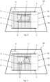
- Fig. 1 is a plan view of a glazing 10 according to the invention having conductors 5 for electrically heating the glazing.
- the glazing 10 is generally trapezoidal in shape, suitable for a vehicle windshield.
- First busbar 1 and second busbar 2 are provided, shown adjacent upper and lower edges of the glazing 1 for connection to an external electrical supply (not shown).
- a third busbar 3 is positioned between first and second busbars, shown as parallel to and closer to first busbar 1.
- Conductors 5 are electrically connected to the first busbar 1.
- a parallel resistor R is arranged to one side of first and second resistors P1, R2 and is electrically in parallel with them so that the same voltage is applied to parallel resistor R and the series combination of first and second resistors R1, R2.
- Parallel resistor R is connected to first and second busbars 1, 2, in the same way as the series combination of first and second resistors R1, R2.
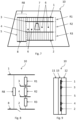
- Fig. 2 is a plan view of another glazing 10 according to the invention. It differs from Fig. 1 in that a split busbar 8 is provided so that a split busbar parallel resistor R8 can have a different distance between busbars than the series combination of first and second resistors R1, R2.
- Split busbar parallel resistor R8 can optionally be electrically connected to second busbar 2, so that it is electrically in parallel with the series combination of first and second resistors R1, R2.
- Fig. 5 is a plan view of a glazing 10 according to the invention. It differs from Fig. 4 by having three gaps 6 in second resistor R2 outside the information acquisition area 7, one on one side thereof and two on the other side, separated by two conductors 5.
- Fig. 8 is a circuit diagram of a glazing 10 according to the invention corresponding to Fig. 7 .
- An optional switch is for an optional electrical connection (not shown in Fig. 7 ) so that split busbar parallel resistor R8 can be electrically in parallel with the series combination of first and second resistors R1, R2.
- Fig. 9 is a cross-section of a glazing 10 according to the invention corresponding to Fig. 3 to Fig. 7 .
- Outer ply of glazing material 11 and inner ply of glazing material 12 have a ply of interlayer material 13 between.
- Table 1 shows results of a first simulation of a glazing generally as Fig. 1 to Fig. 9 of nominal power density 600 W/m 2 .
- Power density in a required region can be increased to 1,228 W/m 2 by having up to twelve fewer conductors in an adjacent region of width 30 mm outside the required region but still in the second resistor R2.
- Number of conductors inside the required region is 23, so total number of conductors in the first resistor R1 is 35.
- removing two conductors, one each to the left and right of the required region increases power density to 665 W/m 2 .
- Table 1 discloses increased power density for a comparative example having no conductors removed (gaps) and four examples having between two and twelve fewer conductors in the second resistor R2 than in the first resistor R1.
- Table 1 Comparative example Example 1
- Example 2 Example 3
- Example 4 Number of conductors fewer (gaps) outside information acquisition area 0 2 4 8 12
- Conductors remaining outside information acquisition area 12 10
- Table 2 shows results of a second simulation of a glazing generally as Fig. 3 to Fig. 6 having nominal power density 600 W/m 2 .
- Power density can be increased in a required region to 742 W/m 2 by having four fewer conductors in an adjacent region of width 10 mm outside the required region but still in the second resistor R2.
- Number of conductors inside the required region is 32, so total number of conductors in the first resistor R1, and in the third resistor R3, is 36.
- Table 2 discloses increased power density for the example having four conductors removed (gaps) in an information acquisition area and having a distance from the second resistor to the first busbar different from a distance from the second resistor to the second busbar.
- Table 2 Parallel resistor R First resistor R1 Second resistor R2 Third resistor R3 Series combination R1+R2+R3 Distance between busbars (mm) 886 56 59 771 886 Width (mm) 522 93 93 93 93 Number of conductors fewer 0 0 4 0 N/A Conductors remaining 201 36 32 36 N/A Resistance (ohms) 0.548 0.194 0.229 2.675 3.098 Power density (W/m 2 ) 600 591 742 591 N/A
- Conductor spacing is 2.6 mm. Conductors are simulated as wires of resistivity 116 ohms/m and having increased path length due to crimped shape of 107%.
- First and second groups of conductors may be partly formed by a plurality of continuous wires which are partly overlapped by at least first, second and third busbars.
- the method of manufacturing may comprise a step of embedding a plurality of conductors in the form of continuous wires in a ply of interlayer material. Preferably, sections of selected continuous wires between the third busbar and the second busbar or the fourth busbar are cut and removed.
Landscapes
- Joining Of Glass To Other Materials (AREA)
- Surface Heating Bodies (AREA)
Claims (11)
- Vitrage (10) comprenant :- des première et deuxième barres collectrices (1, 2) pour un raccordement à une alimentation électrique ;- une troisième barre collectrice (3) positionnée entre les première et deuxième barres collectrices (1, 2) ;- plusieurs conducteurs (5) électriquement raccordés à la première barre collectrice (1) ;dans lequel :- un premier groupe de conducteurs (5) s'étend de la première barre collectrice (1) jusqu'à la troisième barre collectrice (3) pour former une première résistance (R1) ;- un deuxième groupe de conducteurs (5) s'étend à partir d'un côté de la troisième barre collectrice (3) faisant face à la deuxième barre collectrice (2) et est électriquement raccordé à la deuxième barre collectrice (2) pour former une deuxième résistance (R2) ;- dans lequel moins de conducteurs (5) s'étendent à partir du côté de la troisième barre collectrice (3) faisant face à la deuxième barre collectrice (2) que ne s'étendent à partir d'un côté de la troisième barre collectrice (3) faisant face à la première barre collectrice (1) ;caractérisé en ce qu'il comprend de plus :- au moins un espace (6) sur un côté de la troisième barre collectrice (3) opposé à un conducteur (5) sur l'autre côté ;- une zone d'acquisition d'information (7) disposée entre la troisième barre collectrice (3) et la deuxième barre collectrice (2) ;dans lequel le au moins un espace (6) est positionné à l'extérieur de la zone d'acquisition d'information (7).
- Vitrage (10) selon la revendication précédente, comprenant une quatrième barre collectrice (4) positionnée entre la troisième barre collectrice (3) et la deuxième barre collectrice (2) dans lequel :- le deuxième groupe de conducteurs (5) s'étend jusqu'à la quatrième barre collectrice (4) pour former la deuxième résistance (R2) ;- un troisième groupe de conducteurs (5) s'étend à partir de la quatrième barre collectrice (4) jusqu'à la deuxième barre collectrice (2) pour former une troisième résistance (R3).
- Vitrage (10) selon la revendication 2, dans lequel plus de conducteurs (5) s'étendent à partir d'un côté de la quatrième barre collectrice (4) faisant face à la deuxième barre collectrice (2) que ne s'étendent à partir d'un côté de la quatrième barre collectrice (4) faisant face à la troisième barre collectrice (3).
- Vitrage (10) selon l'une quelconque des revendications précédentes, dans lequel la zone d'acquisition d'information (7) est disposée entre la troisième barre collectrice (3) et la quatrième barre collectrice (4).
- Vitrage (10) selon l'une quelconque des revendications précédentes, dans lequel moins de conducteurs (5) s'étendent à partir d'un côté de la troisième barre collectrice (3) faisant face à la deuxième barre collectrice (2) que ne s'étendent à partir d'un côté de la troisième barre collectrice (3) faisant face à la première barre collectrice (1) à l'extérieur de la zone d'acquisition d'information (7).
- Vitrage (10) selon l'une quelconque des revendications précédentes, dans lequel les conducteurs (5) sont des câbles chauffants.
- Vitrage (10) selon l'une quelconque des revendications précédentes, dans lequel un groupe de conducteurs (5) s'étend à partir de la première barre collectrice (1) jusqu'à :- la deuxième barre collectrice (2) pour former une résistance parallèle (R), ou- une barre collectrice fractionnée (8) pour former une résistance parallèle à la barre collectrice fractionnée (R8) et une distance entre la première barre collectrice (1) et la barre collectrice (8) fractionnée est choisie pour être différente d'une distance entre la première barre collectrice (1) et la deuxième barre collectrice (2).
- Vitrage (10) selon l'une quelconque des revendications précédentes, dans lequel une densité de courant dans une région de la deuxième résistance (R2) est supérieure à une densité de courant de la première résistance (R1) ou de la résistance parallèle (R) ou de la résistance parallèle à la barre collectrice fractionnée (R8), ou de toute combinaison de celles-ci.
- Vitrage (10) selon l'une quelconque des revendications précédentes, comprenant des couches externe et interne de matériau de vitrage (11, 12) et une couche de matériau de couche intermédiaire (13) entre celles-ci pour former un verre feuilleté dans lequel des première et deuxième résistances (R1, R2) se trouvent entre la couche de matériau de couche intermédiaire (13) et la couche interne de matériau de vitrage (12).
- Procédé de fabrication d'un vitrage (10) selon la revendication 1, comprenant les étapes de :- fourniture de première et deuxième barres collectrices (1, 2) pour un raccordement à une alimentation électrique ;- positionnement d'une troisième barre collectrice (3) entre les première et deuxième barres collectrices (1, 2) ;- raccordement électrique de plusieurs conducteurs (5) à la première barre collectrice (1) ;- extension d'un premier groupe de conducteurs (5) à partir de la première barre collectrice (1) jusqu'à la troisième barre collectrice (3) pour former une première résistance (R1) ;- extension d'un deuxième groupe de conducteurs (5) à partir d'un côté de la troisième barre collectrice (3) faisant face à la deuxième barre collectrice (2) et raccordement électrique desdits conducteurs (5) à la deuxième barre collectrice (2) pour former une deuxième résistance (R2) ;- dans lequel moins de conducteurs (5) s'étendent à partir du côté de la troisième barre collectrice (3) faisant face à la deuxième barre collectrice (2) que ne s'étendent à partir d'un côté de la troisième barre collectrice (3) faisant face à la première barre collectrice (1) ;- élimination d'au moins une partie d'au moins un conducteur sur un côté de la troisième barre collectrice pour former au moins un espace (6) sur un côté de la troisième barre collectrice (3) opposé à un conducteur (5) sur l'autre côté ;- disposition d'une zone d'acquisition d'information (7) entre la troisième barre collectrice (3) et la deuxième barre collectrice (2) et- positionnement du au moins un espace (6) à l'extérieur de la zone d'acquisition d'information (7).
- Utilisation d'un vitrage (10) selon la revendication 1, dans un véhicule motorisé comme un parebrise, une vitre arrière, vitre latérale ou vitre de toit, ou comme une vitre dans un avion, dans un train ou dans un immeuble.
Applications Claiming Priority (2)
| Application Number | Priority Date | Filing Date | Title |
|---|---|---|---|
| GBGB2000442.0A GB202000442D0 (en) | 2020-01-13 | 2020-01-13 | Glazing, method of manufacturing said glazing and use of said glazing |
| PCT/GB2021/050062 WO2021144558A1 (fr) | 2020-01-13 | 2021-01-12 | Revêtement, procédé de fabrication dudit revêtement et utilisation dudit revêtement |
Publications (2)
| Publication Number | Publication Date |
|---|---|
| EP4091408A1 EP4091408A1 (fr) | 2022-11-23 |
| EP4091408B1 true EP4091408B1 (fr) | 2023-12-20 |
Family
ID=69626311
Family Applications (1)
| Application Number | Title | Priority Date | Filing Date |
|---|---|---|---|
| EP21700347.4A Active EP4091408B1 (fr) | 2020-01-13 | 2021-01-12 | Revêtement, procédé de fabrication dudit revêtement et utilisation dudit revêtement |
Country Status (6)
| Country | Link |
|---|---|
| US (1) | US12382551B2 (fr) |
| EP (1) | EP4091408B1 (fr) |
| JP (1) | JP7691986B2 (fr) |
| CN (1) | CN114982376A (fr) |
| GB (1) | GB202000442D0 (fr) |
| WO (1) | WO2021144558A1 (fr) |
Families Citing this family (1)
| Publication number | Priority date | Publication date | Assignee | Title |
|---|---|---|---|---|
| WO2025196959A1 (fr) * | 2024-03-19 | 2025-09-25 | 三菱自動車工業株式会社 | Vitre de véhicule |
Family Cites Families (27)
| Publication number | Priority date | Publication date | Assignee | Title |
|---|---|---|---|---|
| US6559419B1 (en) * | 2001-08-03 | 2003-05-06 | Centre Luxembourgeois De Recherches Pour Le Verre Et La Ceramique S.A. (C.R.V.C.) | Multi-zone arrangement for heatable vehicle window |
| DE10160806A1 (de) * | 2001-12-11 | 2003-06-26 | Saint Gobain Sekurit D Gmbh | Heizscheibe mit einer elektrisch leitenden Oberflächenbeschichtung |
| US7132625B2 (en) * | 2002-10-03 | 2006-11-07 | Ppg Industries Ohio, Inc. | Heatable article having a configured heating member |
| US6891517B2 (en) * | 2003-04-08 | 2005-05-10 | Ppg Industries Ohio, Inc. | Conductive frequency selective surface utilizing arc and line elements |
| FR2888082B1 (fr) * | 2005-06-30 | 2007-08-24 | Saint Gobain | Vitrage chauffant feuillete ayant un confort de vision ameliore |
| GB0800448D0 (en) * | 2008-01-11 | 2008-02-20 | Pilkington Group Ltd | Electrically heated window |
| DE102008018147A1 (de) * | 2008-04-10 | 2009-10-15 | Saint-Gobain Sekurit Deutschland Gmbh & Co. Kg | Transparente Scheibe mit einer beheizbaren Beschichtung und niederohmigen leitenden Strukturen |
| DE102009030344B4 (de) * | 2009-06-25 | 2024-11-28 | Bayerische Motoren Werke Aktiengesellschaft | Fahrzeugscheibe mit mindestens einem Heizleiter und mindestens einer Antenne |
| DE102009026200A1 (de) * | 2009-07-17 | 2011-02-17 | Saint-Gobain Sekurit Deutschland Gmbh & Co. Kg | Elektrisch großflächig beheizbarer, transparenter Gegenstand, Verfahren zu seiner Herstellung und seine Verwendung |
| EP2334141A1 (fr) | 2009-12-11 | 2011-06-15 | Saint-Gobain Glass France | Vitrage revêtu avec une fenêtre de communication chauffé |
| WO2014112649A1 (fr) * | 2013-01-21 | 2014-07-24 | 旭硝子株式会社 | Corps en forme de plaque chauffé électriquement pour fenêtre |
| CN105981473B (zh) * | 2013-12-16 | 2019-05-31 | 法国圣戈班玻璃厂 | 具有高频透射率的可加热的窗玻璃 |
| PT3362284T (pt) * | 2015-10-13 | 2019-10-14 | Saint Gobain | Placa de vidro laminado para veículo passível de ser aquecida com distribuição melhorada de calor |
| EP3190858A1 (fr) | 2016-01-08 | 2017-07-12 | AGC Glass Europe | Vitrage chauffable |
| JP2017204388A (ja) * | 2016-05-11 | 2017-11-16 | 大日本印刷株式会社 | 導電性発熱体および合わせガラス |
| WO2017204291A1 (fr) | 2016-05-26 | 2017-11-30 | 日本板硝子株式会社 | Verre feuilleté |
| JP6713832B2 (ja) | 2016-05-26 | 2020-06-24 | 日本板硝子株式会社 | ウインドシールド |
| GB201616169D0 (en) | 2016-09-22 | 2016-11-09 | Pilkington Group Limited | Wired laminated window |
| CN107404777B (zh) * | 2017-08-18 | 2020-05-19 | 福耀玻璃工业集团股份有限公司 | 一种汽车前挡夹丝加热玻璃 |
| JP6943135B2 (ja) * | 2017-10-20 | 2021-09-29 | Agc株式会社 | 車両用合わせガラス |
| WO2019078258A1 (fr) * | 2017-10-20 | 2019-04-25 | Agc株式会社 | Verre feuilleté pour véhicule |
| JP7311948B2 (ja) | 2017-11-29 | 2023-07-20 | 日本板硝子株式会社 | ウインドシールド |
| CO2018000469A1 (es) * | 2017-11-30 | 2018-04-30 | Agp America Sa | Laminado automotriz con capa de compensación de sustrato de borde sólido invisible |
| US11575192B2 (en) * | 2017-12-06 | 2023-02-07 | Nippon Sheet Glass Company, Limited | Rear glass |
| KR20200100669A (ko) | 2017-12-28 | 2020-08-26 | 주식회사 쿠라레 | 전자 부재 부착 영역을 갖는 복합 필름 |
| US20230225016A1 (en) * | 2022-01-12 | 2023-07-13 | GM Global Technology Operations LLC | Electrically heated windshield |
| US12476344B2 (en) * | 2022-05-24 | 2025-11-18 | AGC Inc. | Vehicle window glass |
-
2020
- 2020-01-13 GB GBGB2000442.0A patent/GB202000442D0/en not_active Ceased
-
2021
- 2021-01-12 US US17/792,067 patent/US12382551B2/en active Active
- 2021-01-12 WO PCT/GB2021/050062 patent/WO2021144558A1/fr not_active Ceased
- 2021-01-12 JP JP2022542779A patent/JP7691986B2/ja active Active
- 2021-01-12 EP EP21700347.4A patent/EP4091408B1/fr active Active
- 2021-01-12 CN CN202180009206.9A patent/CN114982376A/zh active Pending
Also Published As
| Publication number | Publication date |
|---|---|
| EP4091408A1 (fr) | 2022-11-23 |
| GB202000442D0 (en) | 2020-02-26 |
| WO2021144558A1 (fr) | 2021-07-22 |
| JP2023509993A (ja) | 2023-03-10 |
| US20230052198A1 (en) | 2023-02-16 |
| CN114982376A (zh) | 2022-08-30 |
| US12382551B2 (en) | 2025-08-05 |
| JP7691986B2 (ja) | 2025-06-12 |
Similar Documents
| Publication | Publication Date | Title |
|---|---|---|
| KR101345050B1 (ko) | 전기적으로 광범위하게 가열될 수 있는 투명 물품, 그의 제조 방법, 및 그의 용도 | |
| KR101505330B1 (ko) | 전기 가열성 코팅을 갖는 복합 창유리 | |
| CN101406102B (zh) | 有加热层压系统的透明窗玻璃 | |
| EP1550354B1 (fr) | Article chauffable avec element chauffant configure | |
| KR101999460B1 (ko) | 전기 가열 층을 갖는 투명 판유리 및 그의 제조 방법 | |
| EP0263582A1 (fr) | Procédé de fabrication d'une unité de vision chauffée électriquement | |
| EP3468794B1 (fr) | Vitrage chauffant | |
| EA035749B1 (ru) | Обогреваемое ламинированное боковое стекло | |
| US20040084432A1 (en) | Heatable wiper rest area for a transparency | |
| US20080035629A1 (en) | Electrically Heatable Glazing Panel | |
| EP2063685A1 (fr) | Vitrage en matière plastique | |
| JP2026071264A (ja) | コーティングされた印刷部分を有するグレージングおよびその製造方法およびその使用 | |
| EP3549389B1 (fr) | Vitrage comprenant un réseau de fils chauffants, et son procédé de fabrication | |
| JP4277376B2 (ja) | 通電加熱ガラスとその製造方法 | |
| US12382551B2 (en) | Glazing, method of manufacturing said glazing and use of said glazing | |
| US20240326387A1 (en) | Heatable vehicle glazing | |
| EP4544873A1 (fr) | Vitrage pour une pluralité de capteurs, son procédé de fabrication et son utilisation |
Legal Events
| Date | Code | Title | Description |
|---|---|---|---|
| STAA | Information on the status of an ep patent application or granted ep patent |
Free format text: STATUS: UNKNOWN |
|
| STAA | Information on the status of an ep patent application or granted ep patent |
Free format text: STATUS: THE INTERNATIONAL PUBLICATION HAS BEEN MADE |
|
| PUAI | Public reference made under article 153(3) epc to a published international application that has entered the european phase |
Free format text: ORIGINAL CODE: 0009012 |
|
| STAA | Information on the status of an ep patent application or granted ep patent |
Free format text: STATUS: REQUEST FOR EXAMINATION WAS MADE |
|
| 17P | Request for examination filed |
Effective date: 20220816 |
|
| AK | Designated contracting states |
Kind code of ref document: A1 Designated state(s): AL AT BE BG CH CY CZ DE DK EE ES FI FR GB GR HR HU IE IS IT LI LT LU LV MC MK MT NL NO PL PT RO RS SE SI SK SM TR |
|
| DAV | Request for validation of the european patent (deleted) | ||
| DAX | Request for extension of the european patent (deleted) | ||
| GRAP | Despatch of communication of intention to grant a patent |
Free format text: ORIGINAL CODE: EPIDOSNIGR1 |
|
| STAA | Information on the status of an ep patent application or granted ep patent |
Free format text: STATUS: GRANT OF PATENT IS INTENDED |
|
| INTG | Intention to grant announced |
Effective date: 20230807 |
|
| GRAS | Grant fee paid |
Free format text: ORIGINAL CODE: EPIDOSNIGR3 |
|
| GRAA | (expected) grant |
Free format text: ORIGINAL CODE: 0009210 |
|
| STAA | Information on the status of an ep patent application or granted ep patent |
Free format text: STATUS: THE PATENT HAS BEEN GRANTED |
|
| P01 | Opt-out of the competence of the unified patent court (upc) registered |
Effective date: 20231020 |
|
| AK | Designated contracting states |
Kind code of ref document: B1 Designated state(s): AL AT BE BG CH CY CZ DE DK EE ES FI FR GB GR HR HU IE IS IT LI LT LU LV MC MK MT NL NO PL PT RO RS SE SI SK SM TR |
|
| REG | Reference to a national code |
Ref country code: GB Ref legal event code: FG4D |
|
| REG | Reference to a national code |
Ref country code: CH Ref legal event code: EP |
|
| REG | Reference to a national code |
Ref country code: DE Ref legal event code: R096 Ref document number: 602021007880 Country of ref document: DE |
|
| REG | Reference to a national code |
Ref country code: IE Ref legal event code: FG4D |
|
| PG25 | Lapsed in a contracting state [announced via postgrant information from national office to epo] |
Ref country code: GR Free format text: LAPSE BECAUSE OF FAILURE TO SUBMIT A TRANSLATION OF THE DESCRIPTION OR TO PAY THE FEE WITHIN THE PRESCRIBED TIME-LIMIT Effective date: 20240321 |
|
| REG | Reference to a national code |
Ref country code: LT Ref legal event code: MG9D |
|
| PG25 | Lapsed in a contracting state [announced via postgrant information from national office to epo] |
Ref country code: LT Free format text: LAPSE BECAUSE OF FAILURE TO SUBMIT A TRANSLATION OF THE DESCRIPTION OR TO PAY THE FEE WITHIN THE PRESCRIBED TIME-LIMIT Effective date: 20231220 |
|
| REG | Reference to a national code |
Ref country code: NL Ref legal event code: MP Effective date: 20231220 |
|
| PG25 | Lapsed in a contracting state [announced via postgrant information from national office to epo] |
Ref country code: ES Free format text: LAPSE BECAUSE OF FAILURE TO SUBMIT A TRANSLATION OF THE DESCRIPTION OR TO PAY THE FEE WITHIN THE PRESCRIBED TIME-LIMIT Effective date: 20231220 |
|
| PG25 | Lapsed in a contracting state [announced via postgrant information from national office to epo] |
Ref country code: LT Free format text: LAPSE BECAUSE OF FAILURE TO SUBMIT A TRANSLATION OF THE DESCRIPTION OR TO PAY THE FEE WITHIN THE PRESCRIBED TIME-LIMIT Effective date: 20231220 Ref country code: GR Free format text: LAPSE BECAUSE OF FAILURE TO SUBMIT A TRANSLATION OF THE DESCRIPTION OR TO PAY THE FEE WITHIN THE PRESCRIBED TIME-LIMIT Effective date: 20240321 Ref country code: FI Free format text: LAPSE BECAUSE OF FAILURE TO SUBMIT A TRANSLATION OF THE DESCRIPTION OR TO PAY THE FEE WITHIN THE PRESCRIBED TIME-LIMIT Effective date: 20231220 Ref country code: ES Free format text: LAPSE BECAUSE OF FAILURE TO SUBMIT A TRANSLATION OF THE DESCRIPTION OR TO PAY THE FEE WITHIN THE PRESCRIBED TIME-LIMIT Effective date: 20231220 Ref country code: BG Free format text: LAPSE BECAUSE OF FAILURE TO SUBMIT A TRANSLATION OF THE DESCRIPTION OR TO PAY THE FEE WITHIN THE PRESCRIBED TIME-LIMIT Effective date: 20240320 |
|
| REG | Reference to a national code |
Ref country code: AT Ref legal event code: MK05 Ref document number: 1643583 Country of ref document: AT Kind code of ref document: T Effective date: 20231220 |
|
| PG25 | Lapsed in a contracting state [announced via postgrant information from national office to epo] |
Ref country code: NL Free format text: LAPSE BECAUSE OF FAILURE TO SUBMIT A TRANSLATION OF THE DESCRIPTION OR TO PAY THE FEE WITHIN THE PRESCRIBED TIME-LIMIT Effective date: 20231220 |
|
| PG25 | Lapsed in a contracting state [announced via postgrant information from national office to epo] |
Ref country code: SE Free format text: LAPSE BECAUSE OF FAILURE TO SUBMIT A TRANSLATION OF THE DESCRIPTION OR TO PAY THE FEE WITHIN THE PRESCRIBED TIME-LIMIT Effective date: 20231220 Ref country code: RS Free format text: LAPSE BECAUSE OF FAILURE TO SUBMIT A TRANSLATION OF THE DESCRIPTION OR TO PAY THE FEE WITHIN THE PRESCRIBED TIME-LIMIT Effective date: 20231220 Ref country code: NO Free format text: LAPSE BECAUSE OF FAILURE TO SUBMIT A TRANSLATION OF THE DESCRIPTION OR TO PAY THE FEE WITHIN THE PRESCRIBED TIME-LIMIT Effective date: 20240320 Ref country code: NL Free format text: LAPSE BECAUSE OF FAILURE TO SUBMIT A TRANSLATION OF THE DESCRIPTION OR TO PAY THE FEE WITHIN THE PRESCRIBED TIME-LIMIT Effective date: 20231220 Ref country code: LV Free format text: LAPSE BECAUSE OF FAILURE TO SUBMIT A TRANSLATION OF THE DESCRIPTION OR TO PAY THE FEE WITHIN THE PRESCRIBED TIME-LIMIT Effective date: 20231220 Ref country code: HR Free format text: LAPSE BECAUSE OF FAILURE TO SUBMIT A TRANSLATION OF THE DESCRIPTION OR TO PAY THE FEE WITHIN THE PRESCRIBED TIME-LIMIT Effective date: 20231220 |
|
| PG25 | Lapsed in a contracting state [announced via postgrant information from national office to epo] |
Ref country code: IS Free format text: LAPSE BECAUSE OF FAILURE TO SUBMIT A TRANSLATION OF THE DESCRIPTION OR TO PAY THE FEE WITHIN THE PRESCRIBED TIME-LIMIT Effective date: 20240420 |
|
| PG25 | Lapsed in a contracting state [announced via postgrant information from national office to epo] |
Ref country code: CZ Free format text: LAPSE BECAUSE OF FAILURE TO SUBMIT A TRANSLATION OF THE DESCRIPTION OR TO PAY THE FEE WITHIN THE PRESCRIBED TIME-LIMIT Effective date: 20231220 Ref country code: AT Free format text: LAPSE BECAUSE OF FAILURE TO SUBMIT A TRANSLATION OF THE DESCRIPTION OR TO PAY THE FEE WITHIN THE PRESCRIBED TIME-LIMIT Effective date: 20231220 |
|
| PG25 | Lapsed in a contracting state [announced via postgrant information from national office to epo] |
Ref country code: SK Free format text: LAPSE BECAUSE OF FAILURE TO SUBMIT A TRANSLATION OF THE DESCRIPTION OR TO PAY THE FEE WITHIN THE PRESCRIBED TIME-LIMIT Effective date: 20231220 |
|
| PG25 | Lapsed in a contracting state [announced via postgrant information from national office to epo] |
Ref country code: SM Free format text: LAPSE BECAUSE OF FAILURE TO SUBMIT A TRANSLATION OF THE DESCRIPTION OR TO PAY THE FEE WITHIN THE PRESCRIBED TIME-LIMIT Effective date: 20231220 Ref country code: SK Free format text: LAPSE BECAUSE OF FAILURE TO SUBMIT A TRANSLATION OF THE DESCRIPTION OR TO PAY THE FEE WITHIN THE PRESCRIBED TIME-LIMIT Effective date: 20231220 Ref country code: RO Free format text: LAPSE BECAUSE OF FAILURE TO SUBMIT A TRANSLATION OF THE DESCRIPTION OR TO PAY THE FEE WITHIN THE PRESCRIBED TIME-LIMIT Effective date: 20231220 Ref country code: IT Free format text: LAPSE BECAUSE OF FAILURE TO SUBMIT A TRANSLATION OF THE DESCRIPTION OR TO PAY THE FEE WITHIN THE PRESCRIBED TIME-LIMIT Effective date: 20231220 Ref country code: IS Free format text: LAPSE BECAUSE OF FAILURE TO SUBMIT A TRANSLATION OF THE DESCRIPTION OR TO PAY THE FEE WITHIN THE PRESCRIBED TIME-LIMIT Effective date: 20240420 Ref country code: EE Free format text: LAPSE BECAUSE OF FAILURE TO SUBMIT A TRANSLATION OF THE DESCRIPTION OR TO PAY THE FEE WITHIN THE PRESCRIBED TIME-LIMIT Effective date: 20231220 Ref country code: CZ Free format text: LAPSE BECAUSE OF FAILURE TO SUBMIT A TRANSLATION OF THE DESCRIPTION OR TO PAY THE FEE WITHIN THE PRESCRIBED TIME-LIMIT Effective date: 20231220 Ref country code: AT Free format text: LAPSE BECAUSE OF FAILURE TO SUBMIT A TRANSLATION OF THE DESCRIPTION OR TO PAY THE FEE WITHIN THE PRESCRIBED TIME-LIMIT Effective date: 20231220 |
|
| PG25 | Lapsed in a contracting state [announced via postgrant information from national office to epo] |
Ref country code: PL Free format text: LAPSE BECAUSE OF FAILURE TO SUBMIT A TRANSLATION OF THE DESCRIPTION OR TO PAY THE FEE WITHIN THE PRESCRIBED TIME-LIMIT Effective date: 20231220 Ref country code: PT Free format text: LAPSE BECAUSE OF FAILURE TO SUBMIT A TRANSLATION OF THE DESCRIPTION OR TO PAY THE FEE WITHIN THE PRESCRIBED TIME-LIMIT Effective date: 20240422 |
|
| PG25 | Lapsed in a contracting state [announced via postgrant information from national office to epo] |
Ref country code: PT Free format text: LAPSE BECAUSE OF FAILURE TO SUBMIT A TRANSLATION OF THE DESCRIPTION OR TO PAY THE FEE WITHIN THE PRESCRIBED TIME-LIMIT Effective date: 20240422 Ref country code: PL Free format text: LAPSE BECAUSE OF FAILURE TO SUBMIT A TRANSLATION OF THE DESCRIPTION OR TO PAY THE FEE WITHIN THE PRESCRIBED TIME-LIMIT Effective date: 20231220 |
|
| REG | Reference to a national code |
Ref country code: CH Ref legal event code: PL |
|
| PG25 | Lapsed in a contracting state [announced via postgrant information from national office to epo] |
Ref country code: LU Free format text: LAPSE BECAUSE OF NON-PAYMENT OF DUE FEES Effective date: 20240112 |
|
| REG | Reference to a national code |
Ref country code: DE Ref legal event code: R097 Ref document number: 602021007880 Country of ref document: DE |
|
| PG25 | Lapsed in a contracting state [announced via postgrant information from national office to epo] |
Ref country code: LU Free format text: LAPSE BECAUSE OF NON-PAYMENT OF DUE FEES Effective date: 20240112 Ref country code: MC Free format text: LAPSE BECAUSE OF FAILURE TO SUBMIT A TRANSLATION OF THE DESCRIPTION OR TO PAY THE FEE WITHIN THE PRESCRIBED TIME-LIMIT Effective date: 20231220 |
|
| PG25 | Lapsed in a contracting state [announced via postgrant information from national office to epo] |
Ref country code: DK Free format text: LAPSE BECAUSE OF FAILURE TO SUBMIT A TRANSLATION OF THE DESCRIPTION OR TO PAY THE FEE WITHIN THE PRESCRIBED TIME-LIMIT Effective date: 20231220 |
|
| PG25 | Lapsed in a contracting state [announced via postgrant information from national office to epo] |
Ref country code: BE Free format text: LAPSE BECAUSE OF NON-PAYMENT OF DUE FEES Effective date: 20240131 |
|
| PG25 | Lapsed in a contracting state [announced via postgrant information from national office to epo] |
Ref country code: CH Free format text: LAPSE BECAUSE OF NON-PAYMENT OF DUE FEES Effective date: 20240131 |
|
| PLBE | No opposition filed within time limit |
Free format text: ORIGINAL CODE: 0009261 |
|
| STAA | Information on the status of an ep patent application or granted ep patent |
Free format text: STATUS: NO OPPOSITION FILED WITHIN TIME LIMIT |
|
| PG25 | Lapsed in a contracting state [announced via postgrant information from national office to epo] |
Ref country code: SI Free format text: LAPSE BECAUSE OF FAILURE TO SUBMIT A TRANSLATION OF THE DESCRIPTION OR TO PAY THE FEE WITHIN THE PRESCRIBED TIME-LIMIT Effective date: 20231220 |
|
| PG25 | Lapsed in a contracting state [announced via postgrant information from national office to epo] |
Ref country code: SI Free format text: LAPSE BECAUSE OF FAILURE TO SUBMIT A TRANSLATION OF THE DESCRIPTION OR TO PAY THE FEE WITHIN THE PRESCRIBED TIME-LIMIT Effective date: 20231220 Ref country code: DK Free format text: LAPSE BECAUSE OF FAILURE TO SUBMIT A TRANSLATION OF THE DESCRIPTION OR TO PAY THE FEE WITHIN THE PRESCRIBED TIME-LIMIT Effective date: 20231220 Ref country code: CH Free format text: LAPSE BECAUSE OF NON-PAYMENT OF DUE FEES Effective date: 20240131 Ref country code: BE Free format text: LAPSE BECAUSE OF NON-PAYMENT OF DUE FEES Effective date: 20240131 |
|
| REG | Reference to a national code |
Ref country code: BE Ref legal event code: MM Effective date: 20240131 |
|
| 26N | No opposition filed |
Effective date: 20240923 |
|
| PG25 | Lapsed in a contracting state [announced via postgrant information from national office to epo] |
Ref country code: IE Free format text: LAPSE BECAUSE OF NON-PAYMENT OF DUE FEES Effective date: 20240112 |
|
| PG25 | Lapsed in a contracting state [announced via postgrant information from national office to epo] |
Ref country code: IE Free format text: LAPSE BECAUSE OF NON-PAYMENT OF DUE FEES Effective date: 20240112 |
|
| PG25 | Lapsed in a contracting state [announced via postgrant information from national office to epo] |
Ref country code: CY Free format text: LAPSE BECAUSE OF FAILURE TO SUBMIT A TRANSLATION OF THE DESCRIPTION OR TO PAY THE FEE WITHIN THE PRESCRIBED TIME-LIMIT; INVALID AB INITIO Effective date: 20210112 |
|
| PG25 | Lapsed in a contracting state [announced via postgrant information from national office to epo] |
Ref country code: HU Free format text: LAPSE BECAUSE OF FAILURE TO SUBMIT A TRANSLATION OF THE DESCRIPTION OR TO PAY THE FEE WITHIN THE PRESCRIBED TIME-LIMIT; INVALID AB INITIO Effective date: 20210112 |
|
| PG25 | Lapsed in a contracting state [announced via postgrant information from national office to epo] |
Ref country code: TR Free format text: LAPSE BECAUSE OF FAILURE TO SUBMIT A TRANSLATION OF THE DESCRIPTION OR TO PAY THE FEE WITHIN THE PRESCRIBED TIME-LIMIT Effective date: 20231220 |
|
| PGFP | Annual fee paid to national office [announced via postgrant information from national office to epo] |
Ref country code: GB Payment date: 20260122 Year of fee payment: 6 |
|
| PGFP | Annual fee paid to national office [announced via postgrant information from national office to epo] |
Ref country code: DE Payment date: 20260120 Year of fee payment: 6 |
|
| PGFP | Annual fee paid to national office [announced via postgrant information from national office to epo] |
Ref country code: FR Payment date: 20260128 Year of fee payment: 6 |