EP4091477A1 - Dispositif de génération d'aérosol - Google Patents
Dispositif de génération d'aérosol Download PDFInfo
- Publication number
- EP4091477A1 EP4091477A1 EP21741510.8A EP21741510A EP4091477A1 EP 4091477 A1 EP4091477 A1 EP 4091477A1 EP 21741510 A EP21741510 A EP 21741510A EP 4091477 A1 EP4091477 A1 EP 4091477A1
- Authority
- EP
- European Patent Office
- Prior art keywords
- base body
- infrared radiation
- generation device
- chamber
- radiation layer
- Prior art date
- Legal status (The legal status is an assumption and is not a legal conclusion. Google has not performed a legal analysis and makes no representation as to the accuracy of the status listed.)
- Granted
Links
Images




Classifications
-
- A—HUMAN NECESSITIES
- A24—TOBACCO; CIGARS; CIGARETTES; SIMULATED SMOKING DEVICES; SMOKERS' REQUISITES
- A24F—SMOKERS' REQUISITES; MATCH BOXES; SIMULATED SMOKING DEVICES
- A24F40/00—Electrically operated smoking devices; Component parts thereof; Manufacture thereof; Maintenance or testing thereof; Charging means specially adapted therefor
- A24F40/40—Constructional details, e.g. connection of cartridges and battery parts
-
- A—HUMAN NECESSITIES
- A24—TOBACCO; CIGARS; CIGARETTES; SIMULATED SMOKING DEVICES; SMOKERS' REQUISITES
- A24F—SMOKERS' REQUISITES; MATCH BOXES; SIMULATED SMOKING DEVICES
- A24F40/00—Electrically operated smoking devices; Component parts thereof; Manufacture thereof; Maintenance or testing thereof; Charging means specially adapted therefor
- A24F40/40—Constructional details, e.g. connection of cartridges and battery parts
- A24F40/46—Shape or structure of electric heating means
-
- H—ELECTRICITY
- H05—ELECTRIC TECHNIQUES NOT OTHERWISE PROVIDED FOR
- H05B—ELECTRIC HEATING; ELECTRIC LIGHT SOURCES NOT OTHERWISE PROVIDED FOR; CIRCUIT ARRANGEMENTS FOR ELECTRIC LIGHT SOURCES, IN GENERAL
- H05B3/00—Ohmic-resistance heating
- H05B3/0033—Heating devices using lamps
- H05B3/0038—Heating devices using lamps for industrial applications
- H05B3/0052—Heating devices using lamps for industrial applications for fluid treatments
-
- H—ELECTRICITY
- H05—ELECTRIC TECHNIQUES NOT OTHERWISE PROVIDED FOR
- H05B—ELECTRIC HEATING; ELECTRIC LIGHT SOURCES NOT OTHERWISE PROVIDED FOR; CIRCUIT ARRANGEMENTS FOR ELECTRIC LIGHT SOURCES, IN GENERAL
- H05B3/00—Ohmic-resistance heating
- H05B3/02—Details
- H05B3/03—Electrodes
-
- H—ELECTRICITY
- H05—ELECTRIC TECHNIQUES NOT OTHERWISE PROVIDED FOR
- H05B—ELECTRIC HEATING; ELECTRIC LIGHT SOURCES NOT OTHERWISE PROVIDED FOR; CIRCUIT ARRANGEMENTS FOR ELECTRIC LIGHT SOURCES, IN GENERAL
- H05B3/00—Ohmic-resistance heating
- H05B3/02—Details
- H05B3/06—Heater elements structurally combined with coupling elements or holders
- H05B3/08—Heater elements structurally combined with coupling elements or holders having electric connections specially adapted for high temperatures
-
- H—ELECTRICITY
- H05—ELECTRIC TECHNIQUES NOT OTHERWISE PROVIDED FOR
- H05B—ELECTRIC HEATING; ELECTRIC LIGHT SOURCES NOT OTHERWISE PROVIDED FOR; CIRCUIT ARRANGEMENTS FOR ELECTRIC LIGHT SOURCES, IN GENERAL
- H05B3/00—Ohmic-resistance heating
- H05B3/20—Heating elements having extended surface area substantially in a two-dimensional [2D] plane, e.g. plate-heater
- H05B3/22—Heating elements having extended surface area substantially in a two-dimensional [2D] plane, e.g. plate-heater non-flexible
-
- H—ELECTRICITY
- H05—ELECTRIC TECHNIQUES NOT OTHERWISE PROVIDED FOR
- H05B—ELECTRIC HEATING; ELECTRIC LIGHT SOURCES NOT OTHERWISE PROVIDED FOR; CIRCUIT ARRANGEMENTS FOR ELECTRIC LIGHT SOURCES, IN GENERAL
- H05B3/00—Ohmic-resistance heating
- H05B3/20—Heating elements having extended surface area substantially in a two-dimensional [2D] plane, e.g. plate-heater
- H05B3/22—Heating elements having extended surface area substantially in a two-dimensional [2D] plane, e.g. plate-heater non-flexible
- H05B3/26—Heating elements having extended surface area substantially in a two-dimensional [2D] plane, e.g. plate-heater non-flexible heating conductor mounted on insulating base
-
- A—HUMAN NECESSITIES
- A24—TOBACCO; CIGARS; CIGARETTES; SIMULATED SMOKING DEVICES; SMOKERS' REQUISITES
- A24F—SMOKERS' REQUISITES; MATCH BOXES; SIMULATED SMOKING DEVICES
- A24F40/00—Electrically operated smoking devices; Component parts thereof; Manufacture thereof; Maintenance or testing thereof; Charging means specially adapted therefor
- A24F40/20—Devices using solid inhalable precursors
-
- G—PHYSICS
- G02—OPTICS
- G02B—OPTICAL ELEMENTS, SYSTEMS OR APPARATUS
- G02B3/00—Simple or compound lenses
- G02B3/02—Simple or compound lenses with non-spherical faces
- G02B3/08—Simple or compound lenses with non-spherical faces with discontinuous faces, e.g. Fresnel lens
-
- H—ELECTRICITY
- H05—ELECTRIC TECHNIQUES NOT OTHERWISE PROVIDED FOR
- H05B—ELECTRIC HEATING; ELECTRIC LIGHT SOURCES NOT OTHERWISE PROVIDED FOR; CIRCUIT ARRANGEMENTS FOR ELECTRIC LIGHT SOURCES, IN GENERAL
- H05B2203/00—Aspects relating to Ohmic resistive heating covered by group H05B3/00
- H05B2203/013—Heaters using resistive films or coatings
-
- H—ELECTRICITY
- H05—ELECTRIC TECHNIQUES NOT OTHERWISE PROVIDED FOR
- H05B—ELECTRIC HEATING; ELECTRIC LIGHT SOURCES NOT OTHERWISE PROVIDED FOR; CIRCUIT ARRANGEMENTS FOR ELECTRIC LIGHT SOURCES, IN GENERAL
- H05B2203/00—Aspects relating to Ohmic resistive heating covered by group H05B3/00
- H05B2203/021—Heaters specially adapted for heating liquids
-
- H—ELECTRICITY
- H05—ELECTRIC TECHNIQUES NOT OTHERWISE PROVIDED FOR
- H05B—ELECTRIC HEATING; ELECTRIC LIGHT SOURCES NOT OTHERWISE PROVIDED FOR; CIRCUIT ARRANGEMENTS FOR ELECTRIC LIGHT SOURCES, IN GENERAL
- H05B2203/00—Aspects relating to Ohmic resistive heating covered by group H05B3/00
- H05B2203/03—Heaters specially adapted for heating hand held tools
-
- H—ELECTRICITY
- H05—ELECTRIC TECHNIQUES NOT OTHERWISE PROVIDED FOR
- H05B—ELECTRIC HEATING; ELECTRIC LIGHT SOURCES NOT OTHERWISE PROVIDED FOR; CIRCUIT ARRANGEMENTS FOR ELECTRIC LIGHT SOURCES, IN GENERAL
- H05B2203/00—Aspects relating to Ohmic resistive heating covered by group H05B3/00
- H05B2203/032—Heaters specially adapted for heating by radiation heating
Definitions
- the present disclosure relates to the technical field of aerosol generation, and in particular to an aerosol generation device.
- Heating nonburning tobacco device generally transmits the flavor of the tobacco to consumers through a "heating not burning” method.
- the appearance and consumption mode are similar to traditional cigarettes too, and thus to certain extent can adapt to and meet the physiological needs and psychological needs of consumers.
- Such a "heating not burning” method enables the tobacco to be heated only at a low temperature (generally lower than 500°C); compared with the traditional method of the cigarette tobacco being burned to release smoke, when a heating nonburning tobacco device is employed for smoking, the tobacco is heated at a temperature that is much lower than the temperature of burning the traditional cigarette tobacco, thus greatly reducing the generation of harmful substances in the smoke, preventing the generation of tar and a large number of harmful compounds due to the high-temperature burning of the tobacco; in addition, since there is no side-stream smoke, no second hand smoke will be generated to impact the public environment.
- Existing heating nonburning tobacco devices generally include a resistor heating element, which is inserted into the heating nonburning tobacco or sleeved on the outer circumferential surface of the heating nonburning tobacco during usage; during working, the heating circuit on the resistor heating element is electrified to generate heat so as to heat rather than burn the heating nonburning tobacco, so that the heating nonburning tobacco forms an aerosol.
- existing heating nonburning tobacco devices when heating the heating nonburning tobacco, either heat the heating nonburning tobacco gradually from inside to outside through the resistor heating element, or heat the heating nonburning tobacco gradually from outside to inside through the resistor heating element, thus the speed of aerosol formation is slow.
- the present disclosure provides an aerosol generation device which can increase the speed of aerosol formation.
- the present disclosure provides an aerosol generation device, including a heating element, wherein the heating element includes a base body, an infrared radiation layer, and at least one light convergence mechanism; the base body has a chamber for accommodating an aerosol substrate material; the infrared radiation layer is disposed on a surface of the base body, and is configured to generate infrared radiation to heat the aerosol substrate material disposed in the chamber; the at least one light convergence mechanism is bonded onto the base body and is configured to converge the infrared radiation into the chamber to heat at least a portion of the aerosol substrate material.
- the light convergence mechanism includes a light convergent lens located between the infrared radiation layer and the chamber, and the infrared radiation layer is located on a surface of one side of the base body away from the chamber.
- the light convergent lens is located at a bottom of the chamber, and the infrared radiation layer is located, at least partially, at a lower end surface of an outer surface of the base body.
- the light convergent lens includes a convex lens or/and a Fresnel Lens.
- the base body includes an inner surface close to the chamber and an outer surface disposed opposite to the inner surface, and the light convergent lens is formed between the inner surface and the outer surface.
- the inner surface or outer surface includes a cambered surface convex toward the inside of the chamber or concave away from the chamber.
- the outer surface includes a cambered surface convex toward the inside of the chamber or concave away from the chamber, and the first infrared radiation layer is disposed on the cambered surface.
- the base body is in the shape of a tube and forms one chamber extending along a longitudinal direction
- the light convergent lens includes a strip-shaped convex or concave cambered surface which is formed on the inner surface of the base body and is disposed to extend along the longitudinal direction of the chamber.
- the plurality of the strip-shaped cambered surfaces are disposed equidistantly along the circumference of the chamber, and the infrared radiation layer is disposed, at least partially, surrounding an outer circumferential surface of the base body.
- the base body is in the shape of a circular tube
- the strip-shaped cambered surface is disposed to be convex and extend along the longitudinal direction of the chamber, and a center of a circle to which the cambered surface belongs is located on the outer circumferential surface of the base body.
- the strip-shaped cambered surface has an arc height of 0.03 to 0.3mm.
- the light convergence mechanism and the base body are of an integrated structure, or the light convergence mechanism and the base body are in interference fit connection.
- the light convergence mechanism includes a first light reflection concave surface located in the chamber.
- the base body is in the shape of a tube
- the first light reflection concave surface is located at a bottom wall of the chamber
- the infrared radiation layer is located at a lateral surface of the base body.
- the infrared radiation layer is disposed surrounding the outer circumferential surface of the base body.
- the aerosol generation device further includes a heat insulation tube, the heat insulation tube is sleeved on the base body, the heat insulation tube includes a second light reflection concave surface facing the chamber, and the second light reflection concave surface is configured to converge infrared rays generated by the infrared radiation layer to the aerosol substrate material.
- the base body is in the shape of a tube, an upper end of the base body is an open end, and a lower end of the base body is a closed end;
- the infrared radiation layer further includes a first infrared radiation layer and a second infrared radiation layer, the first infrared radiation layer is located at the lower end surface of the outer surface of the base body, and the second infrared radiation layer is located at the lateral surface of the base body.
- the second infrared radiation layer is disposed surrounding a side wall of the base body, and the second light reflection concave surface is disposed surrounding the outer circumferential surface of the base body.
- the base body is in the shape of a tube, an upper end of the base body is an open end, and a lower end of the base body is a closed end;
- the infrared radiation layer is located, at least partially, at a bottom surface of the base body;
- the aerosol generation device further includes a first electrode and a second electrode, the first electrode is disposed surrounding an outer circumferential edge of the infrared radiation layer and is electrically connected to the infrared radiation layer, and the second electrode elastically abuts against a roughly central area of the infrared radiation layer at the bottom surface of the base body.
- the aerosol generation device further includes a support element detachably connected to the base body, the support element extends at least partially into the chamber and is spaced from the light convergence mechanism by a preset distance, and the support element defines thereon a placement groove configured to place the aerosol substrate material.
- the infrared radiation layer is disposed on the base body to heat the cigarette in an infrared radiation manner, the infrared rays have a good material penetrating power and can heat both inside and outside of the cigarette at the same time, thus enabling a quick speed of aerosol formation;
- the heating element further includes the light convergence mechanism located on the base body, and the light convergence mechanism is configured to converge the infrared rays to the aerosol substrate material, the energy can be better accumulated to the aerosol substrate material, not only improving the utilization of energy, but also increasing the speed of aerosol formation.
- the present disclosure provides an aerosol generation device, including a housing assembly 1, a holder 2, a battery 3, a heating element 4, a support element 5, a first electrode 61, a second electrode 62 and a third electrode 63;
- the housing assembly 1 includes a housing sleeve 11 and an end cover 12, the end cover 12 is arranged to cover an end surface of one end of the housing sleeve 11, and the end cover 12 defines a smoke outlet 121, such that a user may inhale the aerosol through the smoke outlet 121 during usage.
- the holder 2 is housed within the housing sleeve 11 and is connected to the housing sleeve 11, the battery 3 is located within the housing sleeve 11 and is installed on the holder 2.
- the end cover 12 and the holder 2 are both detachably connected to the housing sleeve 11.
- the end cover 12 may be not provided, the holder 2 and the housing sleeve 11 are of an integrated structure. Therefore, no concrete limitation is made to the structures of the housing assembly 1 and the holder 2 here.
- the end cover 12 may also be used as a mouthpiece for inhaling the aerosol. It is understandable that an extra mouthpiece may be used to fit with the end cover 12 to inhale the aerosol, and no concrete limitation is made here.
- the heating element 4 is installed on the holder 2, and includes a base body 41, an infrared radiation layer 42, and at least one light convergence mechanism 43; the base body 41 is in the shape of a tube, an upper end of the base body 41 is an open end, and a lower end of the base body 41 is a closed end.
- a chamber 411 is formed inside the base body 41 and the chamber 411 is configured for accommodating an aerosol substrate material.
- the aerosol substrate material may be cut tobacco, cigarette cream or a cigarette, etc., as long as it can form an aerosol at a preset temperature after being heated. It is understandable that the aerosol substrate material may be placed directly against the inner wall of the chamber 411, also may be disposed spaced from the inner wall of the chamber 411, and no concrete limitation is made here.
- the infrared radiation layer 42 is disposed on a surface of the base body 41, and is configured to generate infrared radiation to heat the aerosol substrate material disposed in the chamber 411. It is understandable that the infrared radiation layer 42 may be electrified itself to generate heat to hereby generate infrared rays, also may be excited to generate infrared rays through the heat conduction of other heating devices, and no concrete limitation is made here. In the present embodiment, the infrared radiation layer 42 is configured to receive an electric power to generate heat to hereby generate infrared rays, and transfer the energy of the infrared rays to the aerosol substrate material at least in a manner of radiation.
- the infrared radiation layer 42 is disposed, at least partially, at a lower end surface of an outer surface of the base body 41, that is, the infrared radiation layer 42 is located, at least partially, at a bottom surface of the base body 41; the infrared radiation layer may be an infrared radiation coating applied on the lower end surface of the outer surface of the base body 41, also may be an infrared radiation film attached to the lower end surface of the outer surface of the base body 41.
- the infrared radiation layer 42 when electrified is capable of generating heat, thereby generating infrared rays of certain wavelength, for example, far infrared rays of 8 ⁇ m to 15 ⁇ m.
- the wavelength of the infrared rays is matched with the wavelength absorbed by the aerosol substrate material, the energy of the infrared rays is easy to be absorbed by the aerosol substrate material.
- the infrared rays may be infrared rays of 0.75 ⁇ m to 1000 ⁇ m, preferably far infrared rays of 1.5 ⁇ m to 400 ⁇ m.
- the infrared radiation layer 42 preferably is a mixture of far-infrared electrothermal ink, ceramic powder and inorganic adhesive that is fully stirred and then coated on the surface of the base body 41 and finally is dried and cured for certain time, and the infrared radiation layer 42 has a thickness of 30 ⁇ m-50 ⁇ m.
- the light convergence mechanism 43 is bonded onto the base body 41 and is configured to converge the infrared radiation into the chamber 411 to heat at least a portion of the aerosol substrate material.
- the light convergence mechanism 43 includes a light convergent lens located between the infrared radiation layer 42 and the chamber 411, and the infrared radiation layer 42 is located on a surface of one side of the base body 41 away from the chamber 411.
- the structure is simple and compact and is convenient to produce.
- the base body 41 includes an inner surface close to the chamber 411 and an outer surface disposed opposite to the inner surface, and the light convergent lens is formed between the inner surface and the outer surface and is located at the bottom of the chamber 411; an upper surface of a bottom wall of the base body 41 is the inner surface, a lower surface of the bottom wall of the base body 41 is the outer surface, that is to say, the light convergence mechanism 43 and the base body 41 are of an integrated structure, that is, the light convergent lens and the base body 41 are of an integrated structure; therefore, the light convergent lens is directly shaped when the base body 41 is being manufactured, without fixing the light convergent lens through other fixing mechanisms, the production is convenient and the reliability is high, the infrared rays are ensured to be better converged to a preset position.
- the light convergent lens is a convex lens, specifically, a plano-convex lens.
- a support element 5 is employed to support the aerosol substrate material to a preset position in the chamber 411.
- An upper end of the support element 5 is in buckling connection with the base body 41 to achieve a detachable connection, the support element 5 extends at least partially into the chamber 411 and is spaced from the light convergence mechanism 43 by a preset distance, so that more infrared rays may be converged.
- the support element 5 defines thereon a placement groove 51 configured to place the aerosol substrate material, a depth of the placement groove 51 may be set as needed, and no concrete limitation is made here.
- the support element 5 is a metal mesh. It is understandable that in some embodiment, the support element 5 also may be not provided, or the support element 5 is fixedly connected to the heating element 4.
- the first electrode 61 is disposed surrounding an outer circumferential edge of the infrared radiation layer 42 and is electrically connected to the infrared radiation layer 42, specifically, the infrared radiation layer 42 is in the shape of a disc, the first electrode 61 is in the shape of a circular ring, an inner circumferential surface of the first electrode 61 comes into contact with an outer circumferential surface of the infrared radiation layer 42, to achieve electrical connection.
- the second electrode 62 elastically abuts against a roughly central area of the infrared radiation layer 42 at the bottom surface of the base body 41, that is, the second electrode 62 may abut against the center of the infrared radiation layer 42, also may be slightly deviated from the center of the infrared radiation layer 42.
- the third electrode 63 is in the shape of a ring and sleeved on the upper end of the base body 41, and is electrically connected to the first electrode 61 through a conductive line 60 disposed on a lateral surface of the base body 41.
- the second electrode 62 is a pogo pin fixed on the holder 2, and the second electrode 62 is electrically connected to the battery 3 to supply power to the infrared radiation layer 42.
- the aerosol generation device further includes a switch (not shown in figures) that is electrically connected to the third electrode 63 and the battery 3 and is configured to control the battery 3 to supply power to the infrared radiation layer 42.
- a switch (not shown in figures) that is electrically connected to the third electrode 63 and the battery 3 and is configured to control the battery 3 to supply power to the infrared radiation layer 42.
- the battery 3 supplies power to the infrared radiation layer 42, so that the infrared radiation layer 42 emits infrared rays to atomize the aerosol substrate material into an aerosol.
- the first electrode 61, the second electrode 62 and the third electrode 63 may be not provided, and the infrared radiation layer 42 is electrically connected to the battery 3 through a conductive line.
- the light convergent lens is a convex lens
- the convex lens is located in the chamber 411 of the base body 41 and is in interference fit connection with the base body 41
- a surface of the convex lens facing the infrared radiation layer 42 is a flat surface
- a surface of the convex lens away from the infrared radiation layer 42 is a spherical surface, that is, the convex lens is a plano-convex lens, thereby being capable of tightly fitting with the interior of the base body 41.
- the light convergent lens is a convex lens
- the convex lens is located in the chamber 411 of the base body 41 and is in interference fit connection with the base body 41
- a surface of the convex lens facing the infrared radiation layer 42 is a concave surface
- a surface of the convex lens away from the infrared radiation layer 42 is a spherical surface, that is, the convex lens is a meniscus lens.
- the light convergent lens is a convex lens
- the convex lens is located in the chamber 411 of the base body 41 and is in interference fit connection with the base body 41
- both of the surfaces of the convex lens facing the infrared radiation layer 42 and away from the infrared radiation layer 42 are a spherical surface, that is, the convex lens is a biconvex lens, thereby being capable of better converging infrared rays.
- the light convergent lens is a Fresnel lens
- the Fresnel lens is located in the chamber 411 of the base body 41 and is in interference fit connection with the base body 41
- a surface of the Fresnel lens facing the infrared radiation layer 42 is a flat surface
- a surface of the Fresnel lens away from the infrared radiation layer 42 includes a plurality of circular grooves that are disposed coaxially.
- the light convergent lens is a Fresnel lens
- the Fresnel lens is located at a bottom wall of the chamber 411 and is integrated with the base body 41, thus the structure is compact. During production, it is not needed to assemble the Fresnel lens separately, the efficiency of production is high.
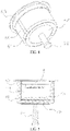
- FIG. 10 is a perspective view of a partial structure of another embodiment of an aerosol generation device according to the present disclosure.
- the base body 41 is in the shape of a tube and forms one chamber 411 extending along a longitudinal direction
- the light convergent lens includes a strip-shaped convex cambered surface which is formed on the inner surface of the base body 41 and is disposed to extend along the longitudinal direction of the chamber 411, that is, the strip-shaped cambered surface is disposed to be convex and extend along the longitudinal direction of the chamber, that is to say, the light convergent lens is integrated with the base body 41 and is disposed in the chamber 411 in a protruding manner.
- the number of the strip-shaped cambered surface and the radian may be set as needed.
- the cigarette 10 generally is strip shaped, when the cigarette 10 is heated the strip-shaped cambered surface is fitting with the cigarette 10, and most areas on the outer surface of the cigarette 10 can acquire converged infrared rays, enabling a quick speed of aerosol formation.
- the aerosol generation device further includes a fourth electrode 64
- the base body 41 is in the shape of a tube with two open ends, there are a plurality of the strip-shaped cambered surfaces, the plurality of the strip-shaped cambered surfaces are disposed equidistantly along the circumference of the chamber 411
- both of the third electrode 63 and the fourth electrode 64 are in the shape of a ring and are sleeved on two opposite ends of the base body 41 respectively
- the infrared radiation layer 42 is disposed, at least partially, surrounding an outer circumferential surface of the base body 41 and is electrically connected to the third electrode 63 and the fourth electrode 64, so that as many infrared rays may be converged to the cigarette 10 as possible.
- the strip-shaped cambered surface has an arc height of 0.03 to 0.3mm, thus the strip-shaped cambered surface can abut against the outer circumferential surface of the cigarette 10, so that the cigarette does not shake arbitrarily in the chamber 411.
- the strip-shaped cambered surface has an arc height of 0.05 to 0.1mm.
- the light convergent lens includes a strip-shaped concave cambered surface which is formed on the inner surface of the base body 41 and is disposed to extend along the longitudinal direction of the chamber 411.
- the infrared rays in the same area between the Points B and C on the base body 41 has the scope of irradiation onto the outer wall of the cigarette 10 changed from 20 degrees to 16 degrees, namely, the same infrared rays are converged to a smaller scope. That is to say, the same energy is concentrated in a smaller scope, then this local temperature will change more quickly, achieving the function of rapid rise of temperature; as the temperature rises rapidly, the aerosol substrate material corresponding to this part has a quicker speed of aerosol formation, which increases the speed of aerosol formation on the whole.
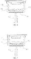
- the light convergence mechanism 43 is a first light reflection concave surface located in the chamber 411.
- the base body 41 of this embodiment is in the shape of a tube
- the infrared radiation layer 42 is located at the lateral surface of the base body 41 and is disposed surrounding the outer circumferential surface of the base body 41.
- the first light reflection concave surface is located at the bottom wall of the chamber 411 and is configured to converge the light emitted by the infrared radiation layer 42 to the aerosol substrate material.
- an inner surface of the bottom wall of the chamber 411 is plated with a first light reflection layer 412
- the first light reflection layer 412 may be made of materials such as silver, aluminum or alloy, etc., and no concrete limitation is made here. It is understandable that the bottom wall of the chamber 411 may also be made of a light reflecting material.
- the first light reflection concave surface is a spherical surface.
- the aerosol generation device further includes a heat insulation tube 7, the heat insulation tube 7 is sleeved on the base body 41, the heat insulation tube 7 includes a second light reflection concave surface 71 facing the chamber 411, the second light reflection concave surface 71 is disposed surrounding the outer circumferential surface of the base body 41, and the second light reflection concave surface 71 is configured to converge infrared rays generated by the infrared radiation layer 42 to the aerosol substrate material.
- an inner surface of the heat insulation tube 7 is plated with a second light reflection layer 72, which may be made of materials such as silver, aluminum or alloy, etc., and no concrete limitation is made here. It is understandable that the heat insulation tube 7 may also be made of a light reflection material.
- the second light reflection concave surface 71 is a spherical surface.
- the base body 41 is in the shape of a tube, an upper end of the base body 41 is an open end, and a lower end of the base body 41 is a closed end.
- Two ends of the base body 41 are sleeved with a third electrode 63 and a fourth electrode 64, a second electrode 62 is disposed below the base body 41; the second electrode 62, the third electrode 63 and the fourth electrode 64 are electrically connected to the battery 3 through a conductive line.
- Both of the third electrode 63 and the fourth electrode 64 are located between the base body 41 and the heat insulation tube 7.
- the infrared radiation layer 42 includes a first infrared radiation layer 421 and a second infrared radiation layer 422, wherein the first infrared radiation layer 421 is located at the lower end surface of the outer surface of the base body 41 and is electrically connected to the second electrode 62 and the fourth electrode 64.
- the second infrared radiation layer 422 is located at the lateral surface of the base body 41 and is electrically connected to the third electrode 63 and the fourth electrode 64, and the second infrared radiation layer 422 is disposed surrounding the side wall of the base body 41.
- the light convergent lens is integrated with the base body 41 and is located at the bottom of the chamber 411.
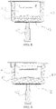
- the base body 41 includes an inner surface close to the chamber 411 and an outer surface disposed opposite to the inner surface, and the light convergent lens is formed between the inner surface and the outer surface, wherein the outer surface includes the lower end surface of the base body 41, the difference lies in that: the lower end surface of the base body 41 of this embodiment is a cambered surface convex toward the inside of the chamber 411, and the first infrared radiation layer 421 is disposed on the cambered surface.
- the bottom wall of the base body 41 is a meniscus lens.
- FIG. 15 provided is a sectional view of a partial structure of another embodiment of an aerosol generation device according to the present disclosure.
- This embodiment has the similar structure to the above one embodiment, the difference lies in that: the lower end surface of the base body 41 of this embodiment is a cambered surface concave away from the inside of the chamber 411, and the first infrared radiation layer 421 is disposed on the cambered surface.
- the bottom wall of the base body 41 is a biconvex lens.
- FIG. 16 provided is a sectional view of a partial structure of another embodiment of an aerosol generation device according to the present disclosure.
- This embodiment has the similar structure to the above one embodiment, the difference lies in that: the lower end surface of the base body 41 of this embodiment is a flat surface, and the bottom wall of the base body 41 is a Fresnel lens.
- the light convergence mechanism 43 of this embodiment includes a first light reflection concave surface located in the chamber 411.
- the base body 41 of this embodiment is in the shape of a tube
- the first light reflection concave surface is located at the bottom wall of the chamber 411
- the infrared radiation layer 42 is located at the lateral surface of the base body 41 and is disposed surrounding the outer circumferential surface of the base body.
- an inner surface of the bottom wall of the chamber 411 is plated with a third light reflection layer 413, which may be made of materials such as silver, aluminum or alloy, etc., and no concrete limitation is made here. It is understandable that the bottom wall of the chamber 411 may also be made of a light reflecting material.
- the infrared radiation layer 42 is disposed on the base body 41 to heat the cigarette in an infrared radiation manner, the infrared rays have a good material penetrating power and can heat both inside and outside of the cigarette at the same time, thus enabling a quick speed of aerosol formation;
- the heating element 4 further includes the light convergence mechanism 43 located on the base body 41, and the light convergence mechanism 43 is configured to converge the infrared rays to the aerosol substrate material, the energy can be better accumulated to the aerosol substrate material, not only improving the utilization of energy, but also increasing the speed of aerosol formation.
Landscapes
- Containers And Packaging Bodies Having A Special Means To Remove Contents (AREA)
- Nozzles (AREA)
- Radiation-Therapy Devices (AREA)
Applications Claiming Priority (2)
| Application Number | Priority Date | Filing Date | Title |
|---|---|---|---|
| CN202010056188.7A CN113133557A (zh) | 2020-01-18 | 2020-01-18 | 气溶胶生成装置 |
| PCT/CN2021/072535 WO2021143909A1 (fr) | 2020-01-18 | 2021-01-18 | Dispositif de génération d'aérosol |
Publications (3)
| Publication Number | Publication Date |
|---|---|
| EP4091477A1 true EP4091477A1 (fr) | 2022-11-23 |
| EP4091477A4 EP4091477A4 (fr) | 2023-07-05 |
| EP4091477B1 EP4091477B1 (fr) | 2025-07-16 |
Family
ID=76808534
Family Applications (1)
| Application Number | Title | Priority Date | Filing Date |
|---|---|---|---|
| EP21741510.8A Active EP4091477B1 (fr) | 2020-01-18 | 2021-01-18 | Dispositif de génération d'aérosol |
Country Status (6)
| Country | Link |
|---|---|
| US (1) | US20230048440A1 (fr) |
| EP (1) | EP4091477B1 (fr) |
| JP (1) | JP7382125B2 (fr) |
| KR (1) | KR102730988B1 (fr) |
| CN (1) | CN113133557A (fr) |
| WO (1) | WO2021143909A1 (fr) |
Cited By (2)
| Publication number | Priority date | Publication date | Assignee | Title |
|---|---|---|---|---|
| WO2025073794A1 (fr) * | 2023-10-06 | 2025-04-10 | Jt International Sa | Dispositif de génération d'aérosol |
| WO2025227389A1 (fr) * | 2024-04-30 | 2025-11-06 | Nicoventures Trading Limited | Générateur d'aérosol pour dispositif de fourniture d'aérosol |
Families Citing this family (6)
| Publication number | Priority date | Publication date | Assignee | Title |
|---|---|---|---|---|
| CN114158786A (zh) * | 2021-11-26 | 2022-03-11 | 深圳麦克韦尔科技有限公司 | 加热组件及气溶胶生成装置 |
| WO2023124532A1 (fr) * | 2021-12-31 | 2023-07-06 | 深圳麦克韦尔科技有限公司 | Dispositif de chauffage et d'atomisation |
| EP4531615A4 (fr) * | 2022-06-02 | 2026-04-22 | Kt & G Corp | Dispositif de génération d'aérosol comprenant un capteur de température |
| CN118923957A (zh) * | 2023-05-09 | 2024-11-12 | 思摩尔国际控股有限公司 | 气溶胶产生装置及发热组件和发热结构 |
| WO2025227395A1 (fr) * | 2024-04-30 | 2025-11-06 | Nicoventures Trading Limited | Générateur d'aérosol pour dispositif de fourniture d'aérosol |
| CN121621605A (zh) * | 2024-08-30 | 2026-03-10 | 思摩尔国际控股有限公司 | 气溶胶产生装置及发热组件 |
Family Cites Families (27)
| Publication number | Priority date | Publication date | Assignee | Title |
|---|---|---|---|---|
| CN1387804A (zh) * | 2001-05-24 | 2003-01-01 | 冷光君 | 香烟点燃器 |
| US20080257367A1 (en) * | 2007-04-23 | 2008-10-23 | Greg Paterno | Electronic evaporable substance delivery device and method |
| CN101620344A (zh) * | 2008-06-30 | 2010-01-06 | 鸿富锦精密工业(深圳)有限公司 | 背光模组及其光学板 |
| US9999250B2 (en) * | 2010-05-15 | 2018-06-19 | Rai Strategic Holdings, Inc. | Vaporizer related systems, methods, and apparatus |
| GB201207054D0 (en) * | 2011-09-06 | 2012-06-06 | British American Tobacco Co | Heating smokeable material |
| CN104643290A (zh) * | 2013-11-19 | 2015-05-27 | 王彦宸 | 一种激光雾化装置 |
| CN103815547B (zh) * | 2014-03-16 | 2017-01-04 | 云南烟草科学研究院 | 一种发热体加热卷烟 |
| WO2015180018A1 (fr) | 2014-05-26 | 2015-12-03 | 深圳麦克韦尔股份有限公司 | Cigarette électronique |
| CN204335822U (zh) * | 2014-11-21 | 2015-05-20 | 黄金珍 | 加热非燃烧型电子烟雾化器和电子烟 |
| CN104522892A (zh) * | 2015-01-14 | 2015-04-22 | 深圳市百康光电有限公司 | 一种光加热电子烟 |
| GB201508405D0 (en) | 2015-05-15 | 2015-07-01 | British American Tobacco Co | Article and apparatus for generating an aerosol |
| US11357261B2 (en) | 2016-04-22 | 2022-06-14 | Jt International S.A. | Aerosol generating device with a laser |
| GB201607474D0 (en) * | 2016-04-29 | 2016-06-15 | British American Tobacco Co | Article, apparatus and method of heating a smokable material |
| TWM529139U (zh) * | 2016-06-24 | 2016-09-21 | Amazing Cool Technology Corp | 輻射集熱器 |
| KR102060860B1 (ko) * | 2016-07-16 | 2019-12-30 | 석인선 | 모듈화된 베이퍼라이저 |
| CN205794814U (zh) * | 2016-07-20 | 2016-12-14 | 湖北中烟工业有限责任公司 | 一种激光热源雾化的电子烟 |
| CN107637862B (zh) * | 2016-07-20 | 2023-11-24 | 贵州中烟工业有限责任公司 | 一种吸烟器 |
| CA3039804C (fr) | 2016-10-12 | 2021-04-13 | Innovosciences Llc | Procede et dispositif de production de vapeur inhalable portable |
| CN206333369U (zh) * | 2016-11-09 | 2017-07-18 | 云南中烟工业有限责任公司 | 一种可靠的光子雾化烟 |
| CN108338415B (zh) * | 2017-01-25 | 2022-05-31 | 贵州中烟工业有限责任公司 | 外围式加热吸烟系统 |
| CN108095203A (zh) * | 2018-02-09 | 2018-06-01 | 昆明纳太科技有限公司 | 一种电加热不燃烧卷烟用辐射式加热装置 |
| CN108378426A (zh) * | 2018-04-23 | 2018-08-10 | 杭州森翼科技有限公司 | 一种使用远红外线加热的电子烟模组 |
| CN209120496U (zh) * | 2018-08-21 | 2019-07-16 | 深圳市子午线信息科技有限公司 | 一种基于纳米远红外的加热装置 |
| CN109077358A (zh) * | 2018-09-19 | 2018-12-25 | 深圳市子午线信息科技有限公司 | 基于纳米远红外分段加热装置及电子烟 |
| CN209628636U (zh) * | 2019-01-02 | 2019-11-15 | 深圳因味科技有限公司 | 一种光加热电子烟 |
| CN109674093A (zh) * | 2019-01-25 | 2019-04-26 | 安徽中烟工业有限责任公司 | 一种内芯式红外辐射加热气雾生成系统 |
| KR102017004B1 (ko) * | 2019-05-22 | 2019-09-02 | 전자부품연구원 | 인쇄형 온도 센서를 이용한 전기 가열식 흡연 장치 |
-
2020
- 2020-01-18 CN CN202010056188.7A patent/CN113133557A/zh active Pending
-
2021
- 2021-01-18 WO PCT/CN2021/072535 patent/WO2021143909A1/fr not_active Ceased
- 2021-01-18 US US17/758,887 patent/US20230048440A1/en active Pending
- 2021-01-18 EP EP21741510.8A patent/EP4091477B1/fr active Active
- 2021-01-18 JP JP2022542285A patent/JP7382125B2/ja active Active
- 2021-01-18 KR KR1020227028357A patent/KR102730988B1/ko active Active
Cited By (2)
| Publication number | Priority date | Publication date | Assignee | Title |
|---|---|---|---|---|
| WO2025073794A1 (fr) * | 2023-10-06 | 2025-04-10 | Jt International Sa | Dispositif de génération d'aérosol |
| WO2025227389A1 (fr) * | 2024-04-30 | 2025-11-06 | Nicoventures Trading Limited | Générateur d'aérosol pour dispositif de fourniture d'aérosol |
Also Published As
| Publication number | Publication date |
|---|---|
| WO2021143909A1 (fr) | 2021-07-22 |
| KR102730988B1 (ko) | 2024-11-14 |
| JP7382125B2 (ja) | 2023-11-16 |
| JP2023510534A (ja) | 2023-03-14 |
| CN113133557A (zh) | 2021-07-20 |
| EP4091477A4 (fr) | 2023-07-05 |
| EP4091477B1 (fr) | 2025-07-16 |
| KR20220127913A (ko) | 2022-09-20 |
| US20230048440A1 (en) | 2023-02-16 |
Similar Documents
| Publication | Publication Date | Title |
|---|---|---|
| EP4091477B1 (fr) | Dispositif de génération d'aérosol | |
| WO2021143839A1 (fr) | Ensemble de chauffage et ensemble à fumer à basse température | |
| US20220322743A1 (en) | Heater and smoking device including the heater | |
| US12274300B2 (en) | Heating device | |
| US12262748B2 (en) | Atomizing device and electronic cigarette | |
| CN210782909U (zh) | 雾化器及电子烟 | |
| US20220338541A1 (en) | Heater and smoking device including heater | |
| CN109561736A (zh) | 一种加热可抽吸材料的加热器及其加热不燃烧发烟设备 | |
| KR20230050400A (ko) | 에어로졸 발생 장치 및 적외선 히터 | |
| EP4620325A1 (fr) | Appareil de génération d'aérosol et structure de chauffage associée | |
| CN213848764U (zh) | 加热器以及包括该加热器的烟具 | |
| WO2021143835A1 (fr) | Dispositif à fumer à basse température | |
| CN211910527U (zh) | 加热器以及包括该加热器的烟具 | |
| WO2021104471A1 (fr) | Élément chauffant et ustensile de cigarette le contenant | |
| CN113080519A (zh) | 加热器以及包含该加热器的烟具 | |
| CN114052300A (zh) | 加热器以及含有该加热器的烟具 | |
| CN113080522A (zh) | 气雾生成装置 | |
| CN115486573A (zh) | 加热组件、气溶胶生成装置及气溶胶生成系统 | |
| CN112841740A (zh) | 加热器以及包含该加热器的烟具 | |
| EP4620326A1 (fr) | Appareil de génération d'aérosol et structure de chauffage associée | |
| CN219353068U (zh) | 气溶胶产生装置及系统 | |
| CN216821793U (zh) | 发热体、加热组件及低温不燃烧加热装置 | |
| CN219500430U (zh) | 一种雾化器 |
Legal Events
| Date | Code | Title | Description |
|---|---|---|---|
| STAA | Information on the status of an ep patent application or granted ep patent |
Free format text: STATUS: THE INTERNATIONAL PUBLICATION HAS BEEN MADE |
|
| PUAI | Public reference made under article 153(3) epc to a published international application that has entered the european phase |
Free format text: ORIGINAL CODE: 0009012 |
|
| STAA | Information on the status of an ep patent application or granted ep patent |
Free format text: STATUS: REQUEST FOR EXAMINATION WAS MADE |
|
| 17P | Request for examination filed |
Effective date: 20220715 |
|
| AK | Designated contracting states |
Kind code of ref document: A1 Designated state(s): AL AT BE BG CH CY CZ DE DK EE ES FI FR GB GR HR HU IE IS IT LI LT LU LV MC MK MT NL NO PL PT RO RS SE SI SK SM TR |
|
| DAV | Request for validation of the european patent (deleted) | ||
| DAX | Request for extension of the european patent (deleted) | ||
| STAA | Information on the status of an ep patent application or granted ep patent |
Free format text: STATUS: EXAMINATION IS IN PROGRESS |
|
| A4 | Supplementary search report drawn up and despatched |
Effective date: 20230607 |
|
| RIC1 | Information provided on ipc code assigned before grant |
Ipc: H05B 3/26 20060101ALI20230601BHEP Ipc: A24F 40/20 20200101ALI20230601BHEP Ipc: A24F 40/46 20200101AFI20230601BHEP |
|
| 17Q | First examination report despatched |
Effective date: 20230619 |
|
| GRAP | Despatch of communication of intention to grant a patent |
Free format text: ORIGINAL CODE: EPIDOSNIGR1 |
|
| STAA | Information on the status of an ep patent application or granted ep patent |
Free format text: STATUS: GRANT OF PATENT IS INTENDED |
|
| RIC1 | Information provided on ipc code assigned before grant |
Ipc: H05B 3/26 20060101ALI20250321BHEP Ipc: A24F 40/20 20200101ALI20250321BHEP Ipc: A24F 40/46 20200101AFI20250321BHEP |
|
| INTG | Intention to grant announced |
Effective date: 20250417 |
|
| GRAS | Grant fee paid |
Free format text: ORIGINAL CODE: EPIDOSNIGR3 |
|
| GRAA | (expected) grant |
Free format text: ORIGINAL CODE: 0009210 |
|
| STAA | Information on the status of an ep patent application or granted ep patent |
Free format text: STATUS: THE PATENT HAS BEEN GRANTED |
|
| AK | Designated contracting states |
Kind code of ref document: B1 Designated state(s): AL AT BE BG CH CY CZ DE DK EE ES FI FR GB GR HR HU IE IS IT LI LT LU LV MC MK MT NL NO PL PT RO RS SE SI SK SM TR |
|
| REG | Reference to a national code |
Ref country code: GB Ref legal event code: FG4D |
|
| REG | Reference to a national code |
Ref country code: CH Ref legal event code: EP |
|
| REG | Reference to a national code |
Ref country code: DE Ref legal event code: R096 Ref document number: 602021034229 Country of ref document: DE |
|
| REG | Reference to a national code |
Ref country code: IE Ref legal event code: FG4D |
|
| REG | Reference to a national code |
Ref country code: NL Ref legal event code: MP Effective date: 20250716 |
|
| PG25 | Lapsed in a contracting state [announced via postgrant information from national office to epo] |
Ref country code: PT Free format text: LAPSE BECAUSE OF FAILURE TO SUBMIT A TRANSLATION OF THE DESCRIPTION OR TO PAY THE FEE WITHIN THE PRESCRIBED TIME-LIMIT Effective date: 20251117 |
|
| PG25 | Lapsed in a contracting state [announced via postgrant information from national office to epo] |
Ref country code: NL Free format text: LAPSE BECAUSE OF FAILURE TO SUBMIT A TRANSLATION OF THE DESCRIPTION OR TO PAY THE FEE WITHIN THE PRESCRIBED TIME-LIMIT Effective date: 20250716 |
|
| REG | Reference to a national code |
Ref country code: AT Ref legal event code: MK05 Ref document number: 1813186 Country of ref document: AT Kind code of ref document: T Effective date: 20250716 |
|
| PG25 | Lapsed in a contracting state [announced via postgrant information from national office to epo] |
Ref country code: IS Free format text: LAPSE BECAUSE OF FAILURE TO SUBMIT A TRANSLATION OF THE DESCRIPTION OR TO PAY THE FEE WITHIN THE PRESCRIBED TIME-LIMIT Effective date: 20251116 |
|
| PG25 | Lapsed in a contracting state [announced via postgrant information from national office to epo] |
Ref country code: NO Free format text: LAPSE BECAUSE OF FAILURE TO SUBMIT A TRANSLATION OF THE DESCRIPTION OR TO PAY THE FEE WITHIN THE PRESCRIBED TIME-LIMIT Effective date: 20251016 |
|
| REG | Reference to a national code |
Ref country code: LT Ref legal event code: MG9D |
|
| PG25 | Lapsed in a contracting state [announced via postgrant information from national office to epo] |
Ref country code: AT Free format text: LAPSE BECAUSE OF FAILURE TO SUBMIT A TRANSLATION OF THE DESCRIPTION OR TO PAY THE FEE WITHIN THE PRESCRIBED TIME-LIMIT Effective date: 20250716 |
|
| PG25 | Lapsed in a contracting state [announced via postgrant information from national office to epo] |
Ref country code: FI Free format text: LAPSE BECAUSE OF FAILURE TO SUBMIT A TRANSLATION OF THE DESCRIPTION OR TO PAY THE FEE WITHIN THE PRESCRIBED TIME-LIMIT Effective date: 20250716 |
|
| PG25 | Lapsed in a contracting state [announced via postgrant information from national office to epo] |
Ref country code: HR Free format text: LAPSE BECAUSE OF FAILURE TO SUBMIT A TRANSLATION OF THE DESCRIPTION OR TO PAY THE FEE WITHIN THE PRESCRIBED TIME-LIMIT Effective date: 20250716 |
|
| PG25 | Lapsed in a contracting state [announced via postgrant information from national office to epo] |
Ref country code: GR Free format text: LAPSE BECAUSE OF FAILURE TO SUBMIT A TRANSLATION OF THE DESCRIPTION OR TO PAY THE FEE WITHIN THE PRESCRIBED TIME-LIMIT Effective date: 20251017 |
|
| PG25 | Lapsed in a contracting state [announced via postgrant information from national office to epo] |
Ref country code: SE Free format text: LAPSE BECAUSE OF FAILURE TO SUBMIT A TRANSLATION OF THE DESCRIPTION OR TO PAY THE FEE WITHIN THE PRESCRIBED TIME-LIMIT Effective date: 20250716 |
|
| PG25 | Lapsed in a contracting state [announced via postgrant information from national office to epo] |
Ref country code: LV Free format text: LAPSE BECAUSE OF FAILURE TO SUBMIT A TRANSLATION OF THE DESCRIPTION OR TO PAY THE FEE WITHIN THE PRESCRIBED TIME-LIMIT Effective date: 20250716 |
|
| PG25 | Lapsed in a contracting state [announced via postgrant information from national office to epo] |
Ref country code: BG Free format text: LAPSE BECAUSE OF FAILURE TO SUBMIT A TRANSLATION OF THE DESCRIPTION OR TO PAY THE FEE WITHIN THE PRESCRIBED TIME-LIMIT Effective date: 20250716 Ref country code: PL Free format text: LAPSE BECAUSE OF FAILURE TO SUBMIT A TRANSLATION OF THE DESCRIPTION OR TO PAY THE FEE WITHIN THE PRESCRIBED TIME-LIMIT Effective date: 20250716 |
|
| PG25 | Lapsed in a contracting state [announced via postgrant information from national office to epo] |
Ref country code: RS Free format text: LAPSE BECAUSE OF FAILURE TO SUBMIT A TRANSLATION OF THE DESCRIPTION OR TO PAY THE FEE WITHIN THE PRESCRIBED TIME-LIMIT Effective date: 20251016 |
|
| PG25 | Lapsed in a contracting state [announced via postgrant information from national office to epo] |
Ref country code: ES Free format text: LAPSE BECAUSE OF FAILURE TO SUBMIT A TRANSLATION OF THE DESCRIPTION OR TO PAY THE FEE WITHIN THE PRESCRIBED TIME-LIMIT Effective date: 20250716 |
|
| PG25 | Lapsed in a contracting state [announced via postgrant information from national office to epo] |
Ref country code: SM Free format text: LAPSE BECAUSE OF FAILURE TO SUBMIT A TRANSLATION OF THE DESCRIPTION OR TO PAY THE FEE WITHIN THE PRESCRIBED TIME-LIMIT Effective date: 20250716 |
|
| PGFP | Annual fee paid to national office [announced via postgrant information from national office to epo] |
Ref country code: GB Payment date: 20260127 Year of fee payment: 6 |
|
| PG25 | Lapsed in a contracting state [announced via postgrant information from national office to epo] |
Ref country code: DK Free format text: LAPSE BECAUSE OF FAILURE TO SUBMIT A TRANSLATION OF THE DESCRIPTION OR TO PAY THE FEE WITHIN THE PRESCRIBED TIME-LIMIT Effective date: 20250716 |
|
| PGFP | Annual fee paid to national office [announced via postgrant information from national office to epo] |
Ref country code: DE Payment date: 20260114 Year of fee payment: 6 |
|
| PG25 | Lapsed in a contracting state [announced via postgrant information from national office to epo] |
Ref country code: IT Free format text: LAPSE BECAUSE OF FAILURE TO SUBMIT A TRANSLATION OF THE DESCRIPTION OR TO PAY THE FEE WITHIN THE PRESCRIBED TIME-LIMIT Effective date: 20250716 |
|
| PGFP | Annual fee paid to national office [announced via postgrant information from national office to epo] |
Ref country code: FR Payment date: 20260128 Year of fee payment: 6 |
|
| PG25 | Lapsed in a contracting state [announced via postgrant information from national office to epo] |
Ref country code: CZ Free format text: LAPSE BECAUSE OF FAILURE TO SUBMIT A TRANSLATION OF THE DESCRIPTION OR TO PAY THE FEE WITHIN THE PRESCRIBED TIME-LIMIT Effective date: 20250716 |
|
| PG25 | Lapsed in a contracting state [announced via postgrant information from national office to epo] |
Ref country code: EE Free format text: LAPSE BECAUSE OF FAILURE TO SUBMIT A TRANSLATION OF THE DESCRIPTION OR TO PAY THE FEE WITHIN THE PRESCRIBED TIME-LIMIT Effective date: 20250716 Ref country code: SK Free format text: LAPSE BECAUSE OF FAILURE TO SUBMIT A TRANSLATION OF THE DESCRIPTION OR TO PAY THE FEE WITHIN THE PRESCRIBED TIME-LIMIT Effective date: 20250716 |