EP4091503A1 - Dispositif de fixation pour chaises et chaise pourvu de dispositif de fixation - Google Patents
Dispositif de fixation pour chaises et chaise pourvu de dispositif de fixation Download PDFInfo
- Publication number
- EP4091503A1 EP4091503A1 EP22172635.9A EP22172635A EP4091503A1 EP 4091503 A1 EP4091503 A1 EP 4091503A1 EP 22172635 A EP22172635 A EP 22172635A EP 4091503 A1 EP4091503 A1 EP 4091503A1
- Authority
- EP
- European Patent Office
- Prior art keywords
- screw
- hole
- fastening device
- adapter
- fastening
- Prior art date
- Legal status (The legal status is an assumption and is not a legal conclusion. Google has not performed a legal analysis and makes no representation as to the accuracy of the status listed.)
- Granted
Links
Images



Classifications
-
- A—HUMAN NECESSITIES
- A47—FURNITURE; DOMESTIC ARTICLES OR APPLIANCES; COFFEE MILLS; SPICE MILLS; SUCTION CLEANERS IN GENERAL
- A47C—CHAIRS; SOFAS; BEDS
- A47C7/00—Parts, details, or accessories of chairs or stools
- A47C7/02—Seat parts
- A47C7/14—Seat parts of adjustable shape; elastically mounted ; adaptable to a user contour or ergonomic seating positions
-
- A—HUMAN NECESSITIES
- A47—FURNITURE; DOMESTIC ARTICLES OR APPLIANCES; COFFEE MILLS; SPICE MILLS; SUCTION CLEANERS IN GENERAL
- A47C—CHAIRS; SOFAS; BEDS
- A47C7/00—Parts, details, or accessories of chairs or stools
- A47C7/02—Seat parts
- A47C7/025—Springs not otherwise provided for in A47C7/22 - A47C7/35
- A47C7/027—Springs not otherwise provided for in A47C7/22 - A47C7/35 with elastomeric springs
-
- A—HUMAN NECESSITIES
- A47—FURNITURE; DOMESTIC ARTICLES OR APPLIANCES; COFFEE MILLS; SPICE MILLS; SUCTION CLEANERS IN GENERAL
- A47C—CHAIRS; SOFAS; BEDS
- A47C7/00—Parts, details, or accessories of chairs or stools
- A47C7/02—Seat parts
- A47C7/34—Seat parts with springs in compression, e.g. coiled
-
- A—HUMAN NECESSITIES
- A47—FURNITURE; DOMESTIC ARTICLES OR APPLIANCES; COFFEE MILLS; SPICE MILLS; SUCTION CLEANERS IN GENERAL
- A47C—CHAIRS; SOFAS; BEDS
- A47C9/00—Stools for specified purposes
- A47C9/002—Stools for specified purposes with exercising means or having special therapeutic or ergonomic effects
Definitions
- the invention relates to a fastening device for fastening a seat shell to a chair frame and a chair with a seat shell and a chair frame, the chair frame being fastened to the seat shell by means of the fastening device according to the invention.
- a skid chair is known in which a seat shell is attached to the chair frame by means of fastening screws.
- the fastening screws run through the seat shell from the top side of the seat shell.
- the screws passed through the seat shell are locked on the chair frame by means of screw nuts.
- the disadvantage here is that the fastening screws are visible on the top of the seat shell. When sitting, these screws can have a negative effect on seating comfort and it can happen that clothing is damaged by the screw heads. On the other hand, dirt can accumulate in the area of the screws or the screw heads, which should be avoided from a hygienic point of view.
- the object of the present invention is therefore to provide a solution with which, on the one hand, thin or less strong seat shells can be attached to a chair frame without the fastening screws being visible on the top of the seat shell, and on the other hand, a chair frame without any further Editing the seat shell can be attached to the seat shell.
- the mounting adapter can be attached to the support surface of the mounting adapter using the adhesive on the underside of the seat shell, the screw itself protruding from the underside of the mounting adapter and the chair frame can thus be attached to the mounting adapter by means of the screw. This makes it possible to attach a chair frame to a seat shell without the seat shell having to be drilled or otherwise pre-processed, or without screws having to be passed through the seat shell.
- the through-hole is arranged in a bottom section of the recess and is dimensioned and designed in such a way that the screw can be arranged in the through-hole with lateral play. This allows manufacturing tolerances or deviations to be compensated.
- the through hole and the screw are dimensioned and the screw can be arranged with lateral play in the through hole such that the screw in the through hole can be tilted relative to a longitudinal axis of the through hole.
- the through hole can be designed in such a way that the screw passed through the through hole is secured against twisting relative to the through hole.
- the screw is secured against turning relative to the through hole in the through hole and on the other hand the screw in the through hole can be tilted relative to a longitudinal axis of the through hole.
- the through-hole has a three- or multi-sided, preferably four-sided, cross-section and a lower section of the screw head or an end section of the screw shank facing the screw head has a cross-section corresponding to the through-hole.
- the fastening adapter can be designed in the shape of a plate.
- a base of the plate-shaped attachment adapter forms the base section of the attachment adapter.
- the fastening device can furthermore comprise a deformable washer which can be arranged between the fastening adapter and the chair frame and through which the screw can be passed.
- a deformable washer which can be arranged between the fastening adapter and the chair frame and through which the screw can be passed.
- the fastening device can also include an optional connection adapter, which can be arranged between the fastening adapter and the chair frame and through which the screw can be passed, with an end section of the connection adapter facing the chair frame being adapted to the outer shape of the corresponding section of the chair frame.
- connection adapter can also be arranged between the washer and the chair frame.
- the recess of the fastening adapter for receiving the screw head of the screw is dimensioned in such a way that the screw head is completely received in the recess. This means that when the screw has been passed through the through hole, the screw head does not protrude from the recess, preferably not even when the screw is inclined relative to the longitudinal axis of the through hole.
- the fastening device can also include a nut with which the fastening device can be locked on the chair frame.
- a flexible or deformable washer can be arranged between the screw head and the bottom section.
- the washer can consist of a flexible plastic, for example.
- the washer can also be firmly connected to the base section.
- the adhesive is adapted to attach the fastener to the seat pan, wherein the adhesive may preferably comprise a silane-modified polymer (MS polymer)-based adhesive.
- MS polymer silane-modified polymer
- FIG. 1 shows a portion of a seat shell 10 of a chair, which is attached to a chair frame 15 by means of an attachment device 20 or is attached. Only a section of the chair frame 15 is also shown here, this section of the chair frame 15 being designed as a round tube.
- this type of attachment is characterized in that even seat shells 10 that have a small strength or thickness can be securely and stably attached to a chair frame 15 without 10 fastening screws being visible on the top of the seat shell are. Boreholes in the seat shell 10 for passing through such fastening screws can therefore be dispensed with. Also on the underside of the seat shell there is no need to drill holes for mounting screws. The stability of the seat shell is not affected by drill holes.
- the fastening device 20 comprises at least one screw 21, a fastening adapter 22 and a nut 26.
- the attachment adapter 22 can have a plate-like shape, as in 2 shown.
- the attachment adapter 22 is not limited to this plate-like shape. Rather, other basic forms can also be provided, provided that a corresponding recess for receiving a screw head is provided on the upper side of the fastening adapter 22, as can be seen from the following description.
- the fastening adapter 22 has a recess or a recess 22b in which the screw head 21a of the screw 21 can be accommodated as completely as possible, so that the screw head 21a does not protrude from the upper side of the fastening adapter 22 .
- a through hole 22a through which the screw 21 is passed from top to bottom is provided at the bottom or bottom portion 22c of the recess 22b. After passing the screw 21 through the through hole 22a, the screw head 21a rests on the bottom portion 22c of the recess or depression 22b.
- the through hole 22a is dimensioned in such a way that the screw 21 has a lateral play in the through hole, ie the screw 21 can be tilted to the side in the through hole.
- the inclination of the fastening adapter can thus be adapted to the seat shell without the fastening adapter itself having to be adapted, ie having to be structurally modified.
- the fastening adapter 22 has a support surface 22d running around the recess or recess 22b, which faces the underside 11 of the seat shell 10 when the fastening adapter is fastened to the underside 11 of the seat shell 10 .
- an adhesive 25 is applied to the bearing surface 22d. After passing the screw 21 through the through hole 22a so that the screw head 21a is in the recess or recess 22b, and after applying the adhesive 25 to the bearing surface 22d, the fastening adapter 22 is fastened to the underside 11 of the seat shell 10, i. glued.
- MS polymer adhesive an adhesive based on silane-modified polymers
- a PU hotmelt adhesive can also be used.
- the screw 21 is mounted with lateral play in the fastening adapter 22 or in the through-hole 22a of the fastening adapter.
- the through hole 22a and a lower section of the screw head 21a or a section of the shank 21b of the screw 21 facing the screw head 21a are designed here such that the screw in the through hole 22a has lateral play, but the screw 21 itself is prevented from turning is secured relative to the mounting adapter 22.
- the shank 21b of the screw 21 protrudes from the underside of the fastening adapter 22 .
- This protruding section of the shank 21b of the screw 21 is then pushed through into a correspondingly dimensioned drill hole in the chair frame 15 and screwed with a screw nut 26 from below.
- the seat shell is thus connected to the chair frame 15 without drill holes having to be provided in the seat shell for the passage of screws.
- the entire attachment of the seat shell to the chair frame does not require drilling or milling, as the fastening device 20 is glued to the underside 11 of the seat shell 10 .
- a flexible or deformable washer 23 can be arranged between the attachment adapter 22 and the chair frame 15, which washer also has a through hole for the screw 21 to pass through.
- the washer 23 is preferably deformable so that it can deform when the fastening device 20 is fastened to the chair frame 15 and can thus adapt to the shape of the chair frame 15 and/or to the shape of the underside of the fastening adapter.
- the washer 23 is preferably made of a plastic.
- connection adapter 24 can be provided between the fastening adapter 22 and the chair frame 15, the lower section of which is adapted to the shape of the chair frame 15.
- This connection adapter also has a through hole for the screw 21 to pass through.
- both the flexible washer 23 and the connection adapter 24 can be provided, so that the flexible washer 23 is pressed between the fastening adapter 22 and the connection adapter 24 when the fastening device 20 is screwed on, as shown in FIG figure 5 shown.
- a cover 30 can be provided with which the nut 26 can be covered.
- the cover 30 serves on the one hand to hide the nut 26 optically.
- the cover serves as a stack protector, that is, as a cover that prevents scratching or damage to the seat surface of the chair underneath when chairs according to the invention are stacked. It is advantageous here if the cover 30 consists of a soft but nevertheless stable plastic.
- FIG. 2 shows an embodiment of a fastening adapter 22 of a fastening device 20 according to the invention.
- the fastening adapter 22 is designed here in the shape of a plate and has a circumferential, overhead contact surface 22d on which the adhesive 25 is applied.
- the mounting adapter has a round base here.
- the base surface can also have any other shape, as long as it has a support surface 22d running all the way round at least in sections for applying the adhesive 25 .
- a recess or a recess 22b is provided which is dimensioned so that the screw head 21a of the Screw 21 can be fully accommodated in it.
- a through hole 22a is provided on the bottom section 22c of the recess 22b, through which the screw can be passed until the screw rests with its screw head 21a on the bottom section 22c.
- the through hole 22a is dimensioned in such a way that the screw passed through the through hole can be inclined against the fastening adapter 22 .
- the through hole 22a is also designed such that the screw passed through the through hole 22a is secured against twisting relative to the fastening adapter 22 .
- a substantially cylindrical wall is provided here between the circumferential bearing surface 22d and the through-hole 22a, so that one or more recesses are formed between the bearing surface 22d and this wall, into which adhesive can also be introduced.
- the attachment adapter 22 can be made of a stable plastic.
- 3 and 4 show the in 1 Fastening device shown in a side view and in a view from the front, each in an exploded view.
- the screw nut 26 is designed here as a sleeve nut that can be inserted on the underside of the tubular chair frame 15, as shown in FIG figure 5 shown.
- figure 5 shows the arrangement of a fastening device 20 according to the invention on the underside 11 of a seat shell 10 and on a tubular chair frame 15.
- the flexible washer 23 and the connection adapter 24 are arranged between the fastening adapter 22 and the tubular section of the chair frame 15, with the underside or the lower section of the connection adapter 24 being adapted to the shape of the chair frame.
- the nut 26 is tightened, the flexible washer 23 is pressed between the attachment adapter 22 and the connection adapter 24 .
- FIG. 6 shows the arrangement of a fastening device 20 according to the invention on the underside 11 of a seat shell 10 and on a receiving plate 17 which is fastened to a chair frame 15.
- the connection adapter 24 can be dispensed with here.
- the flexible or deformable washer 23 which is arranged between the fastening adapter 22 and the receiving plate 17, the gap between the fastening adapter 22 and the receiving plate 17, which has a specific angle, can be compensated.
- connection adapter 24 With a connection adapter, the inclination of the seat shell relative to the chair frame can be adjusted or adjusted in a corresponding configuration. This means that different inclinations of the seat shell relative to the chair frame can be realized with different connection adapters.
- the connection adapters can be wedge-shaped or trapezoidal.
- connection adapter 24 shown can be provided with an appropriate configuration to set or adapt the inclination of the seat shell relative to the chair frame.
- the through hole 22a and the screw 21 are designed in such a way that the screw is seated in the through hole with play and can advantageously be inclined relative to the longitudinal axis of the through hole.
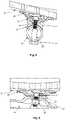
- FIG. 7 shows two examples (figures (a) and (b)) of a screw 22 arranged in a through hole 22a of a fastening adapter 22 of a fastening device according to the invention.
- Figure (a) shows a plate-shaped fastening adapter 22, in which the screw 21 is arranged essentially coaxially with the longitudinal axis LA of the through hole 22a, i.e. the longitudinal axis LA of the through hole 22a is largely identical to the longitudinal axis LAS of the screw 21.
- the screw 21 is arranged here with lateral play in the through hole 22a.
- the screw 21 can be displaced laterally within this lateral play, so that the longitudinal axis LA of the through hole 22a and the longitudinal axis LAS of the screw 21 no longer run coaxially but parallel to one another. This allows tolerance inaccuracies to be easily compensated.
- the screw head 21a of the screw 21 is arranged completely in the recess 22b of the fastening adapter 22, ie the screw head does not protrude from the recess. This prevents the underside of the seat shell from damaging the seat shell when the fastening device is attached to the seat shell. On the other hand, this ensures in particular that the fastening adapter 22 is glued to the seat shell without a protruding screw head impeding the gluing process or even leading to a less stable glued connection.
- Figure (b) shows the same mounting adapter 22 and screw 21 as figure (a).
- the screw 21 is also arranged here with lateral play in the through hole 22a.
- the screw 21 is inclined to the side, i.e. the longitudinal axis LAS of the screw 21 is at a certain angle to the longitudinal axis LA of the through hole 22a.
- the screw head 21a of the screw 21 is arranged completely in the recess 22b of the fastening adapter 22, i.e. the screw head does not protrude from the recess.
- a washer 27 (indicated here with a dashed line) can (optionally) be arranged between the screw head 21a of the screw 21 and the bottom section 22c of the recess 22b.
- This washer 27 can be made of a flexible material, such as rubber, so that it is pressed or squeezed between the screw head 21a and the bottom section 22c when the screw is tightened with the screw nut (not shown here).
- the different distances between the screw head and the base section are thus compensated for by the deformable washer 27 or the space between the screw head and the base section is filled by the flexible or deformable washer 27 .
- the use of a flexible or deformable washer 27 is particularly advantageous when it is necessary for the screw to be arranged in the through hole relative to the longitudinal axis of the through hole.
- the solution according to the invention makes it possible to dispense with bores or other millings in the seat shell in order to accommodate fastening screws for fastening the seat shell to a chair frame.
- the surface of the seat pan and in particular the upper side of the seat pan remain in an intact condition.
- One Attachment of the chair frame to a seat shell is also possible with thin or less strong seat shells.
Landscapes
- Chair Legs, Seat Parts, And Backrests (AREA)
- Chairs Characterized By Structure (AREA)
Applications Claiming Priority (1)
| Application Number | Priority Date | Filing Date | Title |
|---|---|---|---|
| DE102021112731.9A DE102021112731B4 (de) | 2021-05-17 | 2021-05-17 | Befestigungseinrichtung für Stuhl und Stuhl mit Befestigungseinrichtung |
Publications (3)
| Publication Number | Publication Date |
|---|---|
| EP4091503A1 true EP4091503A1 (fr) | 2022-11-23 |
| EP4091503C0 EP4091503C0 (fr) | 2024-04-17 |
| EP4091503B1 EP4091503B1 (fr) | 2024-04-17 |
Family
ID=81603743
Family Applications (1)
| Application Number | Title | Priority Date | Filing Date |
|---|---|---|---|
| EP22172635.9A Active EP4091503B1 (fr) | 2021-05-17 | 2022-05-10 | Dispositif de fixation pour chaises et chaise pourvu de dispositif de fixation |
Country Status (4)
| Country | Link |
|---|---|
| EP (1) | EP4091503B1 (fr) |
| DE (1) | DE102021112731B4 (fr) |
| ES (1) | ES2982900T3 (fr) |
| PL (1) | PL4091503T3 (fr) |
Citations (5)
| Publication number | Priority date | Publication date | Assignee | Title |
|---|---|---|---|---|
| DE1114012B (de) | 1956-10-17 | 1961-09-21 | Ver Schulmoebelfabriken G M B | Stahlrohr-Kufenstuhl als Schulstuhl |
| US4871208A (en) * | 1988-09-06 | 1989-10-03 | Dewey Hodgdon | Chair tilt control mechanism |
| DE202009007017U1 (de) * | 2009-05-15 | 2009-08-20 | Nefe, Ralf | Einstellbare, dynamische Sitzkonstruktion |
| US8540519B1 (en) * | 2010-10-21 | 2013-09-24 | James Lauter | Seated balancing device |
| US20200237099A1 (en) * | 2017-10-11 | 2020-07-30 | Fleetwood Group, Inc. | Fidgeting seating arrangement |
Family Cites Families (3)
| Publication number | Priority date | Publication date | Assignee | Title |
|---|---|---|---|---|
| US2649136A (en) | 1947-03-01 | 1953-08-18 | Herman Miller Furniture Compan | Furniture shock mount construction |
| DE4114458C1 (en) | 1991-05-03 | 1992-11-12 | Fritz Becker Kg, 3492 Brakel, De | Thin plate fastener with head member - which has plate abutting, flat, deposition surface and elongated arrester with dovetail shape |
| KR20050020170A (ko) | 2003-08-21 | 2005-03-04 | (주) 에이치티 | 하이팩 의자의 좌판 제조방법과 하이팩 의자의 좌판 |
-
2021
- 2021-05-17 DE DE102021112731.9A patent/DE102021112731B4/de active Active
-
2022
- 2022-05-10 ES ES22172635T patent/ES2982900T3/es active Active
- 2022-05-10 EP EP22172635.9A patent/EP4091503B1/fr active Active
- 2022-05-10 PL PL22172635.9T patent/PL4091503T3/pl unknown
Patent Citations (5)
| Publication number | Priority date | Publication date | Assignee | Title |
|---|---|---|---|---|
| DE1114012B (de) | 1956-10-17 | 1961-09-21 | Ver Schulmoebelfabriken G M B | Stahlrohr-Kufenstuhl als Schulstuhl |
| US4871208A (en) * | 1988-09-06 | 1989-10-03 | Dewey Hodgdon | Chair tilt control mechanism |
| DE202009007017U1 (de) * | 2009-05-15 | 2009-08-20 | Nefe, Ralf | Einstellbare, dynamische Sitzkonstruktion |
| US8540519B1 (en) * | 2010-10-21 | 2013-09-24 | James Lauter | Seated balancing device |
| US20200237099A1 (en) * | 2017-10-11 | 2020-07-30 | Fleetwood Group, Inc. | Fidgeting seating arrangement |
Also Published As
| Publication number | Publication date |
|---|---|
| PL4091503T3 (pl) | 2024-07-15 |
| ES2982900T3 (es) | 2024-10-18 |
| EP4091503C0 (fr) | 2024-04-17 |
| EP4091503B1 (fr) | 2024-04-17 |
| DE102021112731B4 (de) | 2023-04-20 |
| DE102021112731A1 (de) | 2022-11-17 |
Similar Documents
| Publication | Publication Date | Title |
|---|---|---|
| CH660205A5 (de) | Verstellbares tuer- und fensterband. | |
| DE2514357B2 (de) | Beschlag zum verschwenkbaren Verbinden einer Möbelplatte mit einem feststehenden Möbelteil | |
| DE20019682U1 (de) | Griff für einen Schraubendreher | |
| EP2284335A2 (fr) | Dispositif de palier et rosette formant une partie d'une garniture de poignée | |
| EP1295045A1 (fr) | Dispositif servant a relier deux plaques, notamment des plaques de plan de travail | |
| EP4091503B1 (fr) | Dispositif de fixation pour chaises et chaise pourvu de dispositif de fixation | |
| DE2611323B2 (de) | Einstellvorrichtung für eine der Höhe nach einstellbare obere Schiene eines Schiebeflügels | |
| DE102005045455B4 (de) | Befestigungseinrichtung für eine Möbelabstützung | |
| DE2628019A1 (de) | Erhoehter fussboden | |
| DE202005002790U1 (de) | Bausatz zur Verbindung von Trägerelementen | |
| EP2042677B1 (fr) | Ecran frontal pour un tiroir | |
| DE1759642B2 (de) | Mehrfach verstellbares scharnier | |
| EP1257185A1 (fr) | Element de raccordement pour un meuble, notamment pour une table | |
| DE102016103520B3 (de) | Türzargenanordnung sowie Distanzstück für eine Türzargenanordnung | |
| DE20118506U1 (de) | Rahmen für einen Tür- oder Fensterflügel | |
| EP1582802A1 (fr) | Dispositif de fixation pour écran plat | |
| EP3875787B1 (fr) | Dispositif de fixation pour une structure de meuble | |
| DE3103291A1 (de) | An blend- und fluegelrahmen von fenstern, tueren od.dgl. ansetzbares verbindungselement | |
| DE4239408A1 (en) | Adjustable angle furniture hinge - has protrusions on wedge shaped distance fitting in elongated holes in base | |
| EP0316530B1 (fr) | Ecrou avec position assurée | |
| EP4119754A1 (fr) | Agencement de plaque de fixation et agencement de cadre de porte | |
| DE102020109404A1 (de) | Vorrichtung zum Fixieren eines Möbels an einem Untergrund und Verfahren zum Fixieren eines Möbelkorpus an einem Untergrund | |
| EP1449981A2 (fr) | Dispositif de fixation par serrage pour la fixation de paneaux, notamment de paneaux en verre | |
| DE202021101187U1 (de) | Stuhlführungsvorrichtung mit vereinfachtem Montage -, Reinigungs- und Wartungsaufwand | |
| DE102009060841A1 (de) | Mehrteiliger Beschlag |
Legal Events
| Date | Code | Title | Description |
|---|---|---|---|
| PUAI | Public reference made under article 153(3) epc to a published international application that has entered the european phase |
Free format text: ORIGINAL CODE: 0009012 |
|
| STAA | Information on the status of an ep patent application or granted ep patent |
Free format text: STATUS: THE APPLICATION HAS BEEN PUBLISHED |
|
| AK | Designated contracting states |
Kind code of ref document: A1 Designated state(s): AL AT BE BG CH CY CZ DE DK EE ES FI FR GB GR HR HU IE IS IT LI LT LU LV MC MK MT NL NO PL PT RO RS SE SI SK SM TR |
|
| STAA | Information on the status of an ep patent application or granted ep patent |
Free format text: STATUS: REQUEST FOR EXAMINATION WAS MADE |
|
| 17P | Request for examination filed |
Effective date: 20230523 |
|
| RBV | Designated contracting states (corrected) |
Designated state(s): AL AT BE BG CH CY CZ DE DK EE ES FI FR GB GR HR HU IE IS IT LI LT LU LV MC MK MT NL NO PL PT RO RS SE SI SK SM TR |
|
| RIC1 | Information provided on ipc code assigned before grant |
Ipc: A47C 9/00 20060101ALI20230928BHEP Ipc: A47C 7/34 20060101ALI20230928BHEP Ipc: A47C 7/02 20060101ALI20230928BHEP Ipc: A47C 7/14 20060101AFI20230928BHEP |
|
| GRAP | Despatch of communication of intention to grant a patent |
Free format text: ORIGINAL CODE: EPIDOSNIGR1 |
|
| STAA | Information on the status of an ep patent application or granted ep patent |
Free format text: STATUS: GRANT OF PATENT IS INTENDED |
|
| INTG | Intention to grant announced |
Effective date: 20231106 |
|
| GRAS | Grant fee paid |
Free format text: ORIGINAL CODE: EPIDOSNIGR3 |
|
| GRAA | (expected) grant |
Free format text: ORIGINAL CODE: 0009210 |
|
| STAA | Information on the status of an ep patent application or granted ep patent |
Free format text: STATUS: THE PATENT HAS BEEN GRANTED |
|
| AK | Designated contracting states |
Kind code of ref document: B1 Designated state(s): AL AT BE BG CH CY CZ DE DK EE ES FI FR GB GR HR HU IE IS IT LI LT LU LV MC MK MT NL NO PL PT RO RS SE SI SK SM TR |
|
| REG | Reference to a national code |
Ref country code: GB Ref legal event code: FG4D Free format text: NOT ENGLISH |
|
| REG | Reference to a national code |
Ref country code: CH Ref legal event code: EP |
|
| REG | Reference to a national code |
Ref country code: DE Ref legal event code: R096 Ref document number: 502022000752 Country of ref document: DE |
|
| REG | Reference to a national code |
Ref country code: IE Ref legal event code: FG4D Free format text: LANGUAGE OF EP DOCUMENT: GERMAN |
|
| REG | Reference to a national code |
Ref country code: DE Ref legal event code: R081 Ref document number: 502022000752 Country of ref document: DE Owner name: ASS-EINRICHTUNGSSYSTEME GMBH, DE Free format text: FORMER OWNER: ANMELDERANGABEN UNKLAR / UNVOLLSTAENDIG, 80297 MUENCHEN, DE |
|
| U01 | Request for unitary effect filed |
Effective date: 20240516 |
|
| U07 | Unitary effect registered |
Designated state(s): AT BE BG DE DK EE FI FR IT LT LU LV MT NL PT SE SI Effective date: 20240701 |
|
| U20 | Renewal fee for the european patent with unitary effect paid |
Year of fee payment: 3 Effective date: 20240703 |
|
| PG25 | Lapsed in a contracting state [announced via postgrant information from national office to epo] |
Ref country code: IS Free format text: LAPSE BECAUSE OF FAILURE TO SUBMIT A TRANSLATION OF THE DESCRIPTION OR TO PAY THE FEE WITHIN THE PRESCRIBED TIME-LIMIT Effective date: 20240817 |
|
| PG25 | Lapsed in a contracting state [announced via postgrant information from national office to epo] |
Ref country code: HR Free format text: LAPSE BECAUSE OF FAILURE TO SUBMIT A TRANSLATION OF THE DESCRIPTION OR TO PAY THE FEE WITHIN THE PRESCRIBED TIME-LIMIT Effective date: 20240417 |
|
| PG25 | Lapsed in a contracting state [announced via postgrant information from national office to epo] |
Ref country code: GR Free format text: LAPSE BECAUSE OF FAILURE TO SUBMIT A TRANSLATION OF THE DESCRIPTION OR TO PAY THE FEE WITHIN THE PRESCRIBED TIME-LIMIT Effective date: 20240718 |
|
| REG | Reference to a national code |
Ref country code: ES Ref legal event code: FG2A Ref document number: 2982900 Country of ref document: ES Kind code of ref document: T3 Effective date: 20241018 |
|
| PG25 | Lapsed in a contracting state [announced via postgrant information from national office to epo] |
Ref country code: IS Free format text: LAPSE BECAUSE OF FAILURE TO SUBMIT A TRANSLATION OF THE DESCRIPTION OR TO PAY THE FEE WITHIN THE PRESCRIBED TIME-LIMIT Effective date: 20240817 Ref country code: HR Free format text: LAPSE BECAUSE OF FAILURE TO SUBMIT A TRANSLATION OF THE DESCRIPTION OR TO PAY THE FEE WITHIN THE PRESCRIBED TIME-LIMIT Effective date: 20240417 Ref country code: GR Free format text: LAPSE BECAUSE OF FAILURE TO SUBMIT A TRANSLATION OF THE DESCRIPTION OR TO PAY THE FEE WITHIN THE PRESCRIBED TIME-LIMIT Effective date: 20240718 Ref country code: RS Free format text: LAPSE BECAUSE OF FAILURE TO SUBMIT A TRANSLATION OF THE DESCRIPTION OR TO PAY THE FEE WITHIN THE PRESCRIBED TIME-LIMIT Effective date: 20240717 |
|
| REG | Reference to a national code |
Ref country code: DE Ref legal event code: R097 Ref document number: 502022000752 Country of ref document: DE |
|
| PG25 | Lapsed in a contracting state [announced via postgrant information from national office to epo] |
Ref country code: CZ Free format text: LAPSE BECAUSE OF FAILURE TO SUBMIT A TRANSLATION OF THE DESCRIPTION OR TO PAY THE FEE WITHIN THE PRESCRIBED TIME-LIMIT Effective date: 20240417 |
|
| PG25 | Lapsed in a contracting state [announced via postgrant information from national office to epo] |
Ref country code: SK Free format text: LAPSE BECAUSE OF FAILURE TO SUBMIT A TRANSLATION OF THE DESCRIPTION OR TO PAY THE FEE WITHIN THE PRESCRIBED TIME-LIMIT Effective date: 20240417 Ref country code: RO Free format text: LAPSE BECAUSE OF FAILURE TO SUBMIT A TRANSLATION OF THE DESCRIPTION OR TO PAY THE FEE WITHIN THE PRESCRIBED TIME-LIMIT Effective date: 20240417 |
|
| PG25 | Lapsed in a contracting state [announced via postgrant information from national office to epo] |
Ref country code: SM Free format text: LAPSE BECAUSE OF FAILURE TO SUBMIT A TRANSLATION OF THE DESCRIPTION OR TO PAY THE FEE WITHIN THE PRESCRIBED TIME-LIMIT Effective date: 20240417 |
|
| PG25 | Lapsed in a contracting state [announced via postgrant information from national office to epo] |
Ref country code: SM Free format text: LAPSE BECAUSE OF FAILURE TO SUBMIT A TRANSLATION OF THE DESCRIPTION OR TO PAY THE FEE WITHIN THE PRESCRIBED TIME-LIMIT Effective date: 20240417 Ref country code: SK Free format text: LAPSE BECAUSE OF FAILURE TO SUBMIT A TRANSLATION OF THE DESCRIPTION OR TO PAY THE FEE WITHIN THE PRESCRIBED TIME-LIMIT Effective date: 20240417 Ref country code: RO Free format text: LAPSE BECAUSE OF FAILURE TO SUBMIT A TRANSLATION OF THE DESCRIPTION OR TO PAY THE FEE WITHIN THE PRESCRIBED TIME-LIMIT Effective date: 20240417 Ref country code: CZ Free format text: LAPSE BECAUSE OF FAILURE TO SUBMIT A TRANSLATION OF THE DESCRIPTION OR TO PAY THE FEE WITHIN THE PRESCRIBED TIME-LIMIT Effective date: 20240417 Ref country code: MC Free format text: LAPSE BECAUSE OF FAILURE TO SUBMIT A TRANSLATION OF THE DESCRIPTION OR TO PAY THE FEE WITHIN THE PRESCRIBED TIME-LIMIT Effective date: 20240417 |
|
| PLBE | No opposition filed within time limit |
Free format text: ORIGINAL CODE: 0009261 |
|
| STAA | Information on the status of an ep patent application or granted ep patent |
Free format text: STATUS: NO OPPOSITION FILED WITHIN TIME LIMIT |
|
| 26N | No opposition filed |
Effective date: 20250120 |
|
| PG25 | Lapsed in a contracting state [announced via postgrant information from national office to epo] |
Ref country code: IE Free format text: LAPSE BECAUSE OF NON-PAYMENT OF DUE FEES Effective date: 20240510 |
|
| U20 | Renewal fee for the european patent with unitary effect paid |
Year of fee payment: 4 Effective date: 20250516 |
|
| PGFP | Annual fee paid to national office [announced via postgrant information from national office to epo] |
Ref country code: PL Payment date: 20250424 Year of fee payment: 4 |
|
| PGFP | Annual fee paid to national office [announced via postgrant information from national office to epo] |
Ref country code: ES Payment date: 20250616 Year of fee payment: 4 |
|
| PGFP | Annual fee paid to national office [announced via postgrant information from national office to epo] |
Ref country code: NO Payment date: 20250520 Year of fee payment: 4 |
|
| PGFP | Annual fee paid to national office [announced via postgrant information from national office to epo] |
Ref country code: TR Payment date: 20250505 Year of fee payment: 4 |
|
| PG25 | Lapsed in a contracting state [announced via postgrant information from national office to epo] |
Ref country code: CY Free format text: LAPSE BECAUSE OF FAILURE TO SUBMIT A TRANSLATION OF THE DESCRIPTION OR TO PAY THE FEE WITHIN THE PRESCRIBED TIME-LIMIT; INVALID AB INITIO Effective date: 20220510 |
|
| PG25 | Lapsed in a contracting state [announced via postgrant information from national office to epo] |
Ref country code: HU Free format text: LAPSE BECAUSE OF FAILURE TO SUBMIT A TRANSLATION OF THE DESCRIPTION OR TO PAY THE FEE WITHIN THE PRESCRIBED TIME-LIMIT; INVALID AB INITIO Effective date: 20220510 |
|
| REG | Reference to a national code |
Ref country code: CH Ref legal event code: H13 Free format text: ST27 STATUS EVENT CODE: U-0-0-H10-H13 (AS PROVIDED BY THE NATIONAL OFFICE) Effective date: 20251223 |
|
| PG25 | Lapsed in a contracting state [announced via postgrant information from national office to epo] |
Ref country code: CH Free format text: LAPSE BECAUSE OF NON-PAYMENT OF DUE FEES Effective date: 20250531 |