EP4091539B1 - Dispositif électronique de captage de pression portable - Google Patents
Dispositif électronique de captage de pression portable Download PDFInfo
- Publication number
- EP4091539B1 EP4091539B1 EP21757564.6A EP21757564A EP4091539B1 EP 4091539 B1 EP4091539 B1 EP 4091539B1 EP 21757564 A EP21757564 A EP 21757564A EP 4091539 B1 EP4091539 B1 EP 4091539B1
- Authority
- EP
- European Patent Office
- Prior art keywords
- pressure
- electronic device
- pressure bearing
- component
- pressure sensor
- Prior art date
- Legal status (The legal status is an assumption and is not a legal conclusion. Google has not performed a legal analysis and makes no representation as to the accuracy of the status listed.)
- Active
Links
Images





Classifications
-
- A—HUMAN NECESSITIES
- A61—MEDICAL OR VETERINARY SCIENCE; HYGIENE
- A61B—DIAGNOSIS; SURGERY; IDENTIFICATION
- A61B5/00—Measuring for diagnostic purposes; Identification of persons
- A61B5/02—Detecting, measuring or recording for evaluating the cardiovascular system, e.g. pulse, heart rate, blood pressure or blood flow
- A61B5/021—Measuring pressure in heart or blood vessels
- A61B5/022—Measuring pressure in heart or blood vessels by applying pressure to close blood vessels, e.g. against the skin; Ophthalmodynamometers
- A61B5/02233—Occluders specially adapted therefor
- A61B5/02241—Occluders specially adapted therefor of small dimensions, e.g. adapted to fingers
-
- A—HUMAN NECESSITIES
- A61—MEDICAL OR VETERINARY SCIENCE; HYGIENE
- A61B—DIAGNOSIS; SURGERY; IDENTIFICATION
- A61B5/00—Measuring for diagnostic purposes; Identification of persons
- A61B5/02—Detecting, measuring or recording for evaluating the cardiovascular system, e.g. pulse, heart rate, blood pressure or blood flow
- A61B5/021—Measuring pressure in heart or blood vessels
- A61B5/022—Measuring pressure in heart or blood vessels by applying pressure to close blood vessels, e.g. against the skin; Ophthalmodynamometers
- A61B5/0225—Measuring pressure in heart or blood vessels by applying pressure to close blood vessels, e.g. against the skin; Ophthalmodynamometers the pressure being controlled by electric signals, e.g. derived from Korotkoff sounds
-
- A—HUMAN NECESSITIES
- A61—MEDICAL OR VETERINARY SCIENCE; HYGIENE
- A61B—DIAGNOSIS; SURGERY; IDENTIFICATION
- A61B5/00—Measuring for diagnostic purposes; Identification of persons
- A61B5/0002—Remote monitoring of patients using telemetry, e.g. transmission of vital signals via a communication network
- A61B5/0004—Remote monitoring of patients using telemetry, e.g. transmission of vital signals via a communication network characterised by the type of physiological signal transmitted
-
- A—HUMAN NECESSITIES
- A61—MEDICAL OR VETERINARY SCIENCE; HYGIENE
- A61B—DIAGNOSIS; SURGERY; IDENTIFICATION
- A61B5/00—Measuring for diagnostic purposes; Identification of persons
- A61B5/02—Detecting, measuring or recording for evaluating the cardiovascular system, e.g. pulse, heart rate, blood pressure or blood flow
- A61B5/021—Measuring pressure in heart or blood vessels
- A61B5/02108—Measuring pressure in heart or blood vessels from analysis of pulse wave characteristics
-
- A—HUMAN NECESSITIES
- A61—MEDICAL OR VETERINARY SCIENCE; HYGIENE
- A61B—DIAGNOSIS; SURGERY; IDENTIFICATION
- A61B5/00—Measuring for diagnostic purposes; Identification of persons
- A61B5/02—Detecting, measuring or recording for evaluating the cardiovascular system, e.g. pulse, heart rate, blood pressure or blood flow
- A61B5/021—Measuring pressure in heart or blood vessels
- A61B5/02141—Details of apparatus construction, e.g. pump units or housings therefor, cuff pressurising systems, arrangements of fluid conduits or circuits
-
- A—HUMAN NECESSITIES
- A61—MEDICAL OR VETERINARY SCIENCE; HYGIENE
- A61B—DIAGNOSIS; SURGERY; IDENTIFICATION
- A61B5/00—Measuring for diagnostic purposes; Identification of persons
- A61B5/02—Detecting, measuring or recording for evaluating the cardiovascular system, e.g. pulse, heart rate, blood pressure or blood flow
- A61B5/021—Measuring pressure in heart or blood vessels
- A61B5/022—Measuring pressure in heart or blood vessels by applying pressure to close blood vessels, e.g. against the skin; Ophthalmodynamometers
- A61B5/02225—Measuring pressure in heart or blood vessels by applying pressure to close blood vessels, e.g. against the skin; Ophthalmodynamometers using the oscillometric method
-
- A—HUMAN NECESSITIES
- A61—MEDICAL OR VETERINARY SCIENCE; HYGIENE
- A61B—DIAGNOSIS; SURGERY; IDENTIFICATION
- A61B5/00—Measuring for diagnostic purposes; Identification of persons
- A61B5/02—Detecting, measuring or recording for evaluating the cardiovascular system, e.g. pulse, heart rate, blood pressure or blood flow
- A61B5/021—Measuring pressure in heart or blood vessels
- A61B5/022—Measuring pressure in heart or blood vessels by applying pressure to close blood vessels, e.g. against the skin; Ophthalmodynamometers
- A61B5/02233—Occluders specially adapted therefor
-
- A—HUMAN NECESSITIES
- A61—MEDICAL OR VETERINARY SCIENCE; HYGIENE
- A61B—DIAGNOSIS; SURGERY; IDENTIFICATION
- A61B5/00—Measuring for diagnostic purposes; Identification of persons
- A61B5/68—Arrangements of detecting, measuring or recording means, e.g. sensors, in relation to patient
- A61B5/6801—Arrangements of detecting, measuring or recording means, e.g. sensors, in relation to patient specially adapted to be attached to or worn on the body surface
- A61B5/6802—Sensor mounted on worn items
- A61B5/681—Wristwatch-type devices
-
- A—HUMAN NECESSITIES
- A61—MEDICAL OR VETERINARY SCIENCE; HYGIENE
- A61B—DIAGNOSIS; SURGERY; IDENTIFICATION
- A61B5/00—Measuring for diagnostic purposes; Identification of persons
- A61B5/68—Arrangements of detecting, measuring or recording means, e.g. sensors, in relation to patient
- A61B5/6801—Arrangements of detecting, measuring or recording means, e.g. sensors, in relation to patient specially adapted to be attached to or worn on the body surface
- A61B5/6813—Specially adapted to be attached to a specific body part
- A61B5/6824—Arm or wrist
-
- A—HUMAN NECESSITIES
- A61—MEDICAL OR VETERINARY SCIENCE; HYGIENE
- A61B—DIAGNOSIS; SURGERY; IDENTIFICATION
- A61B5/00—Measuring for diagnostic purposes; Identification of persons
- A61B5/68—Arrangements of detecting, measuring or recording means, e.g. sensors, in relation to patient
- A61B5/6801—Arrangements of detecting, measuring or recording means, e.g. sensors, in relation to patient specially adapted to be attached to or worn on the body surface
- A61B5/683—Means for maintaining contact with the body
- A61B5/6831—Straps, bands or harnesses
-
- A—HUMAN NECESSITIES
- A61—MEDICAL OR VETERINARY SCIENCE; HYGIENE
- A61B—DIAGNOSIS; SURGERY; IDENTIFICATION
- A61B5/00—Measuring for diagnostic purposes; Identification of persons
- A61B5/68—Arrangements of detecting, measuring or recording means, e.g. sensors, in relation to patient
- A61B5/6801—Arrangements of detecting, measuring or recording means, e.g. sensors, in relation to patient specially adapted to be attached to or worn on the body surface
- A61B5/6843—Monitoring or controlling sensor contact pressure
-
- A—HUMAN NECESSITIES
- A61—MEDICAL OR VETERINARY SCIENCE; HYGIENE
- A61B—DIAGNOSIS; SURGERY; IDENTIFICATION
- A61B5/00—Measuring for diagnostic purposes; Identification of persons
- A61B5/74—Details of notification to user or communication with user or patient; User input means
- A61B5/742—Details of notification to user or communication with user or patient; User input means using visual displays
-
- A—HUMAN NECESSITIES
- A61—MEDICAL OR VETERINARY SCIENCE; HYGIENE
- A61B—DIAGNOSIS; SURGERY; IDENTIFICATION
- A61B2562/00—Details of sensors; Constructional details of sensor housings or probes; Accessories for sensors
- A61B2562/02—Details of sensors specially adapted for in-vivo measurements
- A61B2562/0247—Pressure sensors
Definitions
- This application relates to the field of blood pressure measurement technologies, and in particular, to an electronic device.
- An oscillographic method is a blood pressure measurement method with high measurement precision that is widely used in current blood pressure measurement.
- a detection principle of the oscillographic method is as follows: After a user wears a cuff 31, a micro pump is used to inflate an inner cavity of an airbag to pressurize and block a blood vessel 210 of a body part on which the user wears the cuff 31. Then, the micro pump releases air from the inner cavity to gradually stop blocking the blood vessel.
- an oscillation wave signal of air in the cuff 31 is obtained, and an oscillation wave envelope is obtained through fitting.
- a blood pressure value is estimated based on a relationship between the oscillation wave envelope and blood pressure.
- a common cuff blood pressure meter measures blood pressure by using a measurement principle of the oscillographic method.
- the wrist blood pressure meter is small, and is convenient for daily carrying and real-time detection. As the wrist blood pressure meter still uses the airbag 420 to press a body part of the user, the airbag 420 needs to be additionally disposed on the device body 410 of the wearable device 400.
- the airbag 420 and the device body 410 of the wearable device 400 are two separate independent structures with poor integration.
- an effective pressing length of a blood vessel is reduced. Consequently, precision of blood pressure detection is susceptible to disturbance of an interference signal, and is poor in stability. This affects accuracy of a detection result.
- EP 3 026 523 B1 discloses an apparatus for contacting skin with sensor equipment.
- CN 104 434 053 A1 discloses an electronic device for blood pressure measurement.
- US 2019/282169 A1 discloses an electronic device that measures physiological information of a living subject.
- An embodiment of this application provides an electronic device, including a pressing component and a pressure sensor.
- the pressing component is disposed on a wearing structure of the electronic device.
- the pressing component includes an electromagnetic driving member and a pressure bearing member that may move under an electromagnetic force of the electromagnetic driving member.
- the pressure sensor is disposed on the pressure bearing member, and the pressure sensor is located on a surface that is of the wearing structure and that faces a measurement body part of a user.
- the pressure bearing member is configured to be driven by the electromagnetic driving member to press the pressure sensor on the measurement body part.
- the pressure sensor is configured to obtain a pulse wave signal of the measurement body part.
- the pressing component and the pressure sensor are disposed on the wearing structure of the electronic device.
- the pressing component includes the electromagnetic driving member and the pressure bearing member, and the pressure bearing member may move under the electromagnetic force of the electromagnetic driving member.
- the pressure sensor is disposed on the pressure bearing member, and is located on a surface that is of the wearing structure and that faces the measurement body part of the user. In this way, according to one aspect, the pressure sensor may synchronously move with the pressure bearing member, and is driven by the electromagnetic driving member to press the measurement body part, to obtain a pulse wave signal of a measurement body part 0. This implements blood pressure measurement.
- the electromagnetic driving member may be precisely controlled, so that the pressure sensor presses the measurement body part accurately. This helps improve accuracy of blood pressure measurement.
- the pressure bearing member is located on a side that is of the pressure sensor and that is away from the measurement body part. In this way, when the pressure sensor is carried and fastened, the pressure sensor may be disposed close to the measurement body part, so that the pressure sensor presses the measurement body part. This further improves accuracy of blood pressure measurement.
- one of the electromagnetic driving member and the pressure bearing member includes an electromagnet, and the other includes a magnet. Magnetic poles of the electromagnet and magnetic poles of the magnet are disposed opposite to each other.
- the electromagnet has an adjustable polarity, so that when poles of the electromagnet and poles of the magnet repel each other, the pressure sensor is pressed on the measurement body part, or when poles of the electromagnet and poles of the magnet attract each other, the pressure sensor leaves the measurement body part.
- the polarity of the electromagnet may be changed to control movement of the pressure bearing member and the pressure sensor relative to the electromagnetic driving member.
- the pressure sensor may press the measurement body part to obtain the pulse wave signal.
- a magnetic flux strength of the electromagnet may be precisely controlled, so that the pressure sensor presses the measurement body part accurately. This helps improve accuracy of blood pressure measurement.
- the pressure sensor and the pressure bearing member may leave the measurement body part and return to the electronic device.
- the pressure bearing member is fixedly connected to the pressure sensor or is detachably connected to the pressure sensor.
- the pressure sensor may be fastened to the pressure bearing member, and the pressure bearing member supports the pressure sensor.
- the pressure sensor may synchronously move with the pressure bearing member.
- the electronic device may be enhanced in integrated structure.
- the electromagnet includes a magnetic core and a coil wound around an outer peripheral side of the magnetic core.
- a magnetic field is generated around the coil, so that a polarity and a magnetic flux strength of the magnetic field are controlled to drive the pressure bearing member and the pressure sensor to move relative to the measurement par, and the pressure sensor presses the measurement body part accurately. This helps improve accuracy of blood pressure measurement.
- the wearing structure includes a wrist strap and an electronic body.
- the wrist strap is connected to the electronic body, and the pressing component is disposed in the wrist strap.
- the pressing component, the pressure sensor, and the electronic device may be disposed in more diversified manners.
- a mounting cavity is disposed on a surface that is in the wrist strap and that faces the measurement body part, and at least a portion of the pressing component is disposed in the mounting cavity. In this way, it is convenient to mount and fasten the pressing component and the pressure sensor, and the pressing component and the pressure sensor may be disposed close to the measurement body part. This facilitates pressing of the measurement body part and blood pressure measurement.
- the pressure bearing member is slidably connected to an inner wall of the mounting cavity. In this way, when the pressure bearing member is mounted in the mounting cavity, it may be convenient for the pressure bearing member to be driven by the electromagnetic driving member to move. This reduces abrasion caused to the pressure bearing member and prolongs a service life of the electronic device.
- the device further includes at least one sliding component.
- the sliding component is connected between the pressure bearing member and the inner wall of the mounting cavity, so that the pressure bearing member is slidably connected to the inner wall of the mounting cavity.
- sliding components there are a plurality of sliding components, and the sliding components are disposed in different directions on a peripheral side of the pressure bearing member.
- sliding between the pressure bearing member and the mounting cavity may be more stable, and stability performance of the pressing component in the wrist strap may be enhanced. This helps improve a pressing effect of the pressure sensor.
- connection manners of the pressure bearing member and the mounting cavity may be more diversified.
- each sliding component includes a first pulley disposed on a side wall of the pressure bearing member and a slide rail disposed on the inner wall of the mounting cavity.
- the pulley and the slide rail are disposed opposite to each other, and the first pulley may slide along the slide rail, so that the pressure bearing member is slidably connected to the inner wall of the mounting cavity.
- the sliding between the pressure bearing member and the mounting cavity may be smoother, and the pressure bearing member may slide according to a set track of the slide rail.
- a limiting part is disposed at an opening of the mounting cavity, and the limiting part is correspondingly disposed outside the first pulley in a pressing direction.
- a movable stroke of the pressure bearing member may be limited through the limiting part.
- the first pulley may be shielded, so as to enhance aesthetics and sealing performance of the electronic device.
- a guide member is further disposed between the pressure bearing member and the electromagnetic driving member.
- a first guide groove corresponding to the guide member is further disposed in the electromagnetic driving member.
- a first end of the guide member is connected to the magnet, and a second end of the guide member passes through the first guide groove and may move in an extension direction of the first guide groove.
- the sliding component includes a second pulley, a connection arm, and a second guide groove.
- the second guide groove and the mounting cavity are fastened relative to each other, and an extension direction of the second guide groove is staggered with a pressing direction of the electromagnetic driving member.
- a first end of the connection arm is hinged with the pressure bearing member, the second pulley is disposed at a second end of the connection arm, and the second pulley can slide in the guide groove, so that the connection arm drives the pressure bearing member to move in the pressing direction.
- the pressure sensor when the pressure sensor presses the measurement body part, the pressure sensor may be disposed in a more diversified manner. This helps improve diversity of the electronic device.
- the device further includes a processor.
- the processor is configured to measure a blood pressure value of the user based on the obtained pulse wave signal. In this way, blood pressure of the user may be measured through the processor and the pressure sensor, so that the user monitors the blood pressure in real time and manages the blood pressure.
- the device further includes a display.
- the display is electrically connected to the processor, and is configured to display the blood pressure value. In this way, the measured blood pressure value may be intuitively displayed through the display, so that it is convenient for the user to obtain the blood pressure value.
- the device includes the wearing structure, the pressing component, and the pressure sensor.
- the pressing component is disposed on the wearing structure, and the pressure sensor is disposed on the pressing component.
- a micro pump (not shown in the figure) is used to inflate an inner cavity of an airbag of the cuff 31 to pressurize and block a blood vessel of a body part on which the user wears the cuff 31. Then, the micro pump releases air from the inner cavity to gradually stop blocking the blood vessel.
- an air pressure sensor detects a pressure wave signal in the inner cavity
- an oscillation wave signal of air in the cuff 31 is obtained after the pressure wave signal is filtered, and an oscillation wave envelope is obtained through fitting.
- a blood pressure value is estimated based on a relationship between the oscillation wave envelope and blood pressure.
- an airbag 420 is disposed on a device body 410 of a wearable device 400, to form an existing wearable electronic device for blood pressure measurement, for example, a wrist sphygmomanometer, like a wrist sphygmomanometer shown in FIG. 6 .
- the wrist sphygmomanometer is small and convenient for daily carrying and real-time detection.
- the wrist sphygmomanometer still uses a measurement principle of the oscillographic method, and uses the airbag 420 to press a body part of the user.
- the airbag 420 needs to be additionally disposed on the foregoing device body 410.
- the airbag 420 is usually disposed on a side that is of the device body 410 and that is close to the wrist (namely, an inner side of the wearable device 400), and is not connected to the wearable device 400.
- the airbag 420 and the device body 410 of the wearable device 400 are two separate independent structures with poor integration.
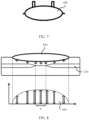
- FIG. 7 and FIG. 8 after the airbag 420 of the wearable device 400 expands to be an ellipsoid, an effective pressing length L of a blood vessel 210 is reduced. Consequently, precision of blood pressure detection is susceptible to disturbance of an interference signal, and is poor in stability. This affects accuracy of a detection result.
- an embodiment of this application provides an electronic device, so that the electronic device is wearable and may measure blood pressure anytime and anywhere. This helps improve accuracy of blood pressure measurement.
- the electronic device includes but is not limited to a wearable device or the like.
- the wearable device includes but is not limited to a watch 100 or a smartwatch.
- FIG. 9 is a schematic diagram of a structure of an electronic device according to an embodiment of this application.
- FIG. 10 is a schematic diagram of a structure of an electronic device worn on a wrist according to an embodiment of this application.
- FIG. 11 is a schematic diagram of a structure of an electronic device from another perspective according to an embodiment of this application.
- FIG. 12 is a partial sectional view that shows a part A of the electronic device in FIG. 11 .
- FIG. 13 is a top view of the electronic device in FIG. 12 .
- FIG. 14 is a schematic diagram of a structure of the electronic device in FIG. 12 during blood pressure measurement.
- FIG. 9 and FIG. 10 show a watch.
- the watch 100 is used as an example to further describe the electronic device in this application.
- the watch 100 may include a pressing component 20 and a pressure sensor 30, and the pressing component 20 is disposed on a wearing structure 10 of the electronic device.
- the pressing component 20 includes an electromagnetic driving member 21 and a pressure bearing member 22 that may move under an electromagnetic force of the electromagnetic driving member 21, and the pressure sensor 30 is disposed on the pressure bearing member 22. In this way, the pressure bearing member 22 may be fastened relative to the pressure sensor 30 while supporting the pressure sensor 30.
- the pressure sensor 30 is located on a surface that is of the wearing structure 10 and that faces the measurement body part 200 of a user, and is configured to press the measurement body part 200 when measuring blood pressure for the measurement body part 200.
- the pressure bearing member 22 is driven by the electromagnetic driving member 21 to press the pressure sensor 30 on the measurement body part 200.
- the pressure sensor 30 is configured to obtain a pulse wave signal of the measurement body part 200, to measure blood pressure.
- the pulse wave signal in this embodiment is the same as the pressure wave signal mentioned in the background, and includes an oscillation wave signal and a pressure signal.
- the electronic device in this embodiment of this application may filter and perform fitting processing on the forging pulse wave signal to obtain an oscillation wave envelope through the oscillographic method, and estimate a blood pressure value based on a relationship between the oscillation wave envelope and blood pressure, to measure blood pressure.
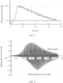
- the electronic device in this application may measure blood pressure by applying continuously changing pressure, as shown in FIG. 3 .
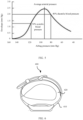
- the electronic device may measure blood pressure at a pressure value (for example, 100 mm Hg). It should be noted that when a pressure value is used to measure blood pressure, the pressure value needs to be greater than average arterial pressure in FIG. 5 , to ensure validity and accuracy of a measurement result.
- the pressure sensor 30 may transmit the obtained pulse wave signal to a processor 50 of the electronic device.
- the processor 50 filters and performs fitting processing on the pulse wave signal, and estimates the blood pressure value based on the relationship between the oscillation wave envelope and the blood pressure, to measure blood pressure of the measurement body part 200.
- the pressure sensor 30 may transmit the obtained pulse wave signal to a PC end outside the electronic device.
- the PC end filters and performs fitting processing on the pulse wave signal, and estimates the blood pressure value based on the relationship between the oscillation wave envelope and the blood pressure, to measure blood pressure of the measurement body part 200.
- a signal transmission manner of the pressure sensor 30 is not further limited.
- the electronic device may alternatively be another apparatus that can be worn on a wrist.
- the electronic device in this application includes but is not limited to the watch 100.
- the watch 100 includes but is not limited to a smartwatch.
- a processor inside the smartwatch may be used to process the pulse wave signal and calculate the blood pressure value.
- the pressing component 20 may be disposed on the wearing structure 10 of the electronic device. It may be understood that the pressing component 20 may be disposed on a wearing body of the electronic device.
- the wearing body may include a wrist strap 11, or an electronic body 12 of the electronic device, or a wrist strap 11 and an electronic body 12 of the electronic device.
- the watch 100 shown in FIG. 9 to FIG. 11 is used as an example.
- the wearing structure 10 may include the wrist strap 11 and the electronic body 12.
- the wrist strap 11 is connected to the electronic body 12 in a rotating manner.
- the electronic body 12 may be understood as a watch body of the watch 100.
- the pressing component 20 may be disposed in the wrist strap 11. Refer to FIG. 10 and FIG. 11 .
- the pressure sensor 30 on the pressure bearing member 22 presses the measurement body part 200 (for example, an artery of the wrist) of the user.
- the pressing component 20 may be disposed in the electronic body 12, that is, the pressing component 20 may alternatively be disposed in the watch body, and the pressure sensor 30 may press the measurement body part 200 of the user.
- the measurement body part 200 pressed by the pressure sensor 30 is the back of the wrist rather than an artery inside the wrist.
- the electronic body 12 of the electronic device may be rotated to the artery inside the wrist (even if the electronic body 12 is rotated to a direction opposite to that in FIG. 10 and worn on the wrist), so that the pressure sensor 30 can press the artery. In this way, a structure of the wrist strap 11 of the electronic device is not affected while blood pressure is measured.
- the electronic device is further described by disposing the pressing component 20 in the wrist strap 11.
- the pressing component 20 includes an electromagnetic driving member 21 and a pressure bearing member 22.
- the pressure bearing member 22 may move under an electromagnetic force of the electromagnetic driving member 21. Because the pressure sensor 30 is disposed on the pressure bearing member 22, the pressure bearing member 22 is fastened relative to the pressure sensor 30 while supporting the pressure sensor 30. In other words, the pressure sensor 30 may synchronously moves with the pressure bearing member 22 when the pressure bearing member 22 is driven by the electromagnetic driving member 21. In this way, when blood pressure needs to be measured, the electromagnetic driving member 21 may drive the pressure bearing member 22 to move in a direction towards the measurement body part 200 of the user, so as to drive the pressure sensor 30 to move in the direction towards the measurement body part 200. This implements pressing on the measurement body part. In this way, a pulse wave signal of the measurement body part 200 is obtained, so that the blood pressure is measured.
- a driving force of the electromagnetic driving member 21 may be precisely controlled, so that the pressure sensor 30 presses the measurement body part 200 accurately. This helps improve accuracy of blood pressure measurement.
- the pressure sensor 30 is disposed on the wearing structure 10 of the electronic device through the pressing component 20.
- real-time blood pressure measurement may be implemented, so that it is convenient for the user to monitor and manage blood pressure.
- a blood pressure measurement apparatus is greatly reduced in size than the cuff blood pressure meter 300 in the conventional technology, so that functions of an existing electronic device are more diversified.
- the electronic device in this application when blood pressure is measured in an airbag pressing manner, comfort of a user is low.
- the cuff blood pressure meter 300 measures blood pressure
- the cuff 31 is bound to an upper arm of the user, and an airbag in the cuff 31 is used to press the entire upper arm (as shown in FIG. 2 ).
- the electronic device in this application measures blood pressure
- the electromagnetic driving member 21 drives the pressure bearing member 22 to press the measurement body part 200 by driving the pressure sensor 30
- the pressure sensor 30 presses only the measurement body part 200 rather than the entire measurement body part 200 of the body. Therefore, compared with the airbag pressing manner in the conventional technology, the electronic device in this application helps improve comfort of the measurement body part 200.
- the pressing component 20 and the pressure sensor 30 are disposed on the wearing structure 10 of the electronic device.
- the pressing component 20 includes the electromagnetic driving member 21 and the pressure bearing member 22, and the pressure bearing member 22 may move under the electromagnetic force of the electromagnetic driving member 21.
- the pressure sensor 30 is disposed on the pressure bearing member 22, and is located on a surface that is of the wearing structure 10 and that faces the measurement body part 200 of the user. In this way, in one aspect, the pressure sensor 30 may synchronously move with the pressure bearing member 22, and is driven by the electromagnetic driving member 21 to press the measurement body part 200, to obtain a pulse wave signal of the measurement body part 200. This implements blood pressure measurement.
- the electromagnetic driving member 21 may be precisely controlled, so that the pressure sensor 30 presses the measurement body part 200 accurately.
- both the pressing component 20 and the pressure sensor 30 are disposed on the wearing structure 10 of the electronic device, so that the electronic device in this application has a higher degree of integration than an existing wearable device used for blood pressure measurement, and can facilitate daily carrying and real-time blood pressure monitoring. In this way, blood pressure management is implemented for the user.
- the pressure sensor 30 presses the measurement body part 200. This helps improve comfort of the measurement body part 200.
- the pressure bearing member 22 may be located on a side that is of the pressure sensor 30 and that is away from the measurement body part 200, that is, the pressure bearing member 22 is disposed towards a side that is of the pressure sensor 30 and that is away from the measurement body part 200 while carrying the pressure sensor 30. In this way, when the pressure sensor 30 is carried and fastened, and the pressure sensor 30 may be disposed close to the measurement body part 200, to shorten a distance between the pressure sensor 30 and the measurement body part 200. In this way, in one aspect, it may be convenient for the pressure sensor 30 to press the measurement body part 200, so that accuracy of blood pressure measurement is further improved. In another aspect, a movement path of the pressure bearing member 22 may be shortened, so that a requirement for a driving force of the electromagnetic driving member 21 is reduced.
- a movement direction of the pressure bearing member 22 is from the electromagnetic driving member 21 towards the measurement body part 200.
- the pressure bearing member 22 is disposed close to the electromagnetic driving member 21, and is located in the wearing structure 10.
- the pressing component 20 is disposed in the wearing structure 10 (in a state shown in FIG. 12 ), and the pressing component 20 is hidden through the wearing structure 10. This helps improve aesthetics of the electronic device.
- the pressure bearing member 22 is driven by the electromagnetic driving member 21 to drive the pressure sensor 30 to move towards the measurement body part 200.
- the magnet 221 may be a permanent magnet 221 or another magnetic module. That is, in this embodiment, the magnet 221 includes but is not limited to the permanent magnet 221.
- a guide member 23 (as shown in FIG. 12 and FIG. 14 ) is further disposed between the pressure bearing member 22 and the electromagnetic driving member 21, a first guide groove 213 corresponding to the guide member 23 is further disposed in the electromagnetic driving member 21, a first end of the guide member 23 is connected to the magnet 221, and a second end of the guide member 23 passes through the first guide groove 213 and may move in an extension direction of the first guide groove 213. In this way, the guide member 23 slides in the first guide groove 213, so that movement of the pressure bearing member 22 may be better guided.
- a surface that is of the pressure sensor 30 and that is close to the measurement body part 200 is closer to the measurement body part 200 than a surface that is of the wearing structure 10 and that is close to the measurement body part 200, so that at least a portion of the pressure sensor 30 is exposed inside the wrist strap 11.
- the pressure sensor 30 may be disposed in a more diversified manner. This helps improve diversity of the electronic device.
- FIG. 15 is a principle block diagram of blood pressure measurement performed by an electronic device according to an embodiment of this application.
- the electronic device further includes a processor 50.
- the processor 50 is electrically connected to the pressure sensor 30.
- the processor 50 is configured to filter and perform fitting processing on an obtained pulse wave signal, and measure a blood pressure value of a user based on the obtained pulse wave signal. In this way, blood pressure of the user may be measured through the processor 50 and the pressure sensor 30, so that the user monitors the blood pressure in real time and manages the blood pressure.
- the processor 50 may be an electronic device such as a processor 50 in a smartwatch, and the processor 50 processes a pulse wave signal and calculates a blood pressure value.
- the processor 50 may be a microcontroller unit (microcontroller unit, MCU).
- the digital/analog conversion module 91 is configured to convert a digital control signal sent by the processor 50 into an analog signal, so as to control whether the electromagnet is powered on and a direction of a current. In this way, existence of a magnetic field of the electromagnet and a polarity of the electromagnet are controlled.
- the pressure sensor 30 is electrically connected to the processor 50 through the analog-to-digital conversion module 92.
- the analog-to-digital conversion module 92 is configured to obtain a pulse wave signal of the pressure sensor 30, convert the pulse wave signal into a digital signal, and transmit the digital signal to the processor 50.
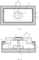
- FIG. 16 is a schematic diagram of another structure of the electronic device in FIG. 12 according to an embodiment of this application.
- FIG. 17 is a top view of the electronic device in FIG. 16 according to an embodiment of this application.
- FIG. 18 is a schematic diagram of a structure of the electronic device in FIG. 16 according to an embodiment of this application during blood pressure measurement.
- connection arm 43 may also be located on the outer sidewall of the wrist strap 11 and located outside the mounting cavity 111.
Landscapes
- Health & Medical Sciences (AREA)
- Life Sciences & Earth Sciences (AREA)
- Cardiology (AREA)
- Engineering & Computer Science (AREA)
- Biomedical Technology (AREA)
- Public Health (AREA)
- Veterinary Medicine (AREA)
- Biophysics (AREA)
- Pathology (AREA)
- Physics & Mathematics (AREA)
- General Health & Medical Sciences (AREA)
- Heart & Thoracic Surgery (AREA)
- Medical Informatics (AREA)
- Molecular Biology (AREA)
- Surgery (AREA)
- Animal Behavior & Ethology (AREA)
- Vascular Medicine (AREA)
- Physiology (AREA)
- Ophthalmology & Optometry (AREA)
- Dentistry (AREA)
- Computer Networks & Wireless Communication (AREA)
- Measuring Pulse, Heart Rate, Blood Pressure Or Blood Flow (AREA)
Claims (12)
- Dispositif électronique portable (100), comprenant :un élément de pressage (20) ;un capteur de pression (30) ;dans lequel l'élément de pressage (20) comprend un élément d'entraînement électromagnétique (21) et un élément de support de pression (22) ; dans lequel l'élément de support de pression (22) peut se déplacer sous l'effet d'une force électromagnétique de l'élément d'entraînement électromagnétique (21) ;le capteur de pression (30) est disposé sur l'élément de support de pression (22), et le capteur de pression (30) est situé sur une surface de l'élément de support de pression (22) et qui fait face à une partie de corps de mesure d'un utilisateur ;l'élément de support de pression (22) est configuré pour être entraîné par l'élément d'entraînement électromagnétique (21) afin de presser le capteur de pression (30) sur la partie de corps de mesure, etle capteur de pression (30) est configuré pour détecter un signal d'onde de pouls de la partie de corps de mesure,dans lequel le dispositif électronique comprend un bracelet (11) et un corps électronique (12), le bracelet (11) est relié au corps électronique (12) et l'élément de pression (20) est disposé dans le bracelet (11),dans lequel une cavité de montage est disposée sur une surface qui se trouve dans le bracelet (11) et qui fait face à la partie de corps de mesure, et au moins une partie de l'élément de pressage (20) est disposée dans la cavité de montage (111),dans lequel l'élément de support de pression (22) est relié de manière coulissante à une paroi intérieure de la cavité de montage (111).
- Dispositif électronique selon la revendication 1, dans lequel, lorsque le capteur de pression (30) est pressé sur la partie de corps de mesure par l'élément de support de pression (22), une direction de mouvement de l'élément de support de pression (22) va de l'élément d'entraînement électromagnétique (21) vers la partie de corps de mesure.
- Dispositif électronique selon la revendication 1 ou 2, dans lequel l'un parmi l'élément d'entraînement électromagnétique (21) et l'élément de support de pression (22) comprend un électro-aimant, et l'autre comprend un aimant ; et des pôles magnétiques de l'électro-aimant et des pôles magnétiques de l'aimant sont opposés l'un à l'autre ; et l'électro-aimant a une polarité réglable, de sorte que lorsque des pôles de l'électro-aimant et des pôles de l'aimant se repoussent, le capteur de pression (30) est pressé sur la partie de corps de mesure, ou lorsque des pôles de l'électro-aimant et des pôles de l'aimant s'attirent, le capteur de pression (30) quitte la partie de corps de mesure.
- Dispositif électronique selon la revendication 3, dans lequel l'élément de support de pression (22) est relié de manière fixe au capteur de pression (30) ou est relié de manière amovible au capteur de pression (30).
- Dispositif électronique selon la revendication 3 ou 4, dans lequel l'électro-aimant comprend un noyau magnétique et une bobine enroulée autour d'un côté périphérique extérieur du noyau magnétique.
- Dispositif électronique selon l'une quelconque des revendications 1 à 5, comprenant en outre au moins un élément coulissant, dans lequel l'élément coulissant est relié entre l'élément de support de pression (22) et la paroi intérieure de la cavité de montage (111), de sorte que l'élément de support de pression (22) est relié de manière coulissante à la paroi intérieure de la cavité de montage (111).
- Dispositif électronique selon la revendication 6, dans lequel chaque élément coulissant comprend une première poulie disposée sur une paroi latérale de l'élément de support de pression (22) et une glissière disposée sur la paroi intérieure de la cavité de montage (111), la poulie et la glissière sont disposées à l'opposé l'une de l'autre, et la première poulie peut coulisser le long de la glissière, de sorte que l'élément de support de pression (22) est relié de manière coulissante à la paroi intérieure de la cavité de montage (111).
- Dispositif électronique selon la revendication 7, dans lequel une pièce de limitation est disposée au niveau d'une ouverture de la cavité de montage (111), et la pièce de limitation est disposée de manière correspondante à l'extérieur de la première poulie dans une direction de pression.
- Dispositif électronique selon la revendication 7 ou 8 et selon la revendication 3, dans lequel un élément de guidage est en outre disposé entre l'élément de support de pression (22) et l'élément d'entraînement électromagnétique (21), une première rainure de guidage correspondant à l'élément de guidage est en outre disposée dans l'élément d'entraînement électromagnétique (21), une première extrémité de l'élément de guidage est reliée à l'aimant, et une seconde extrémité de l'élément de guidage passe à travers la première rainure de guidage et peut se déplacer dans une direction d'extension de la première rainure de guidage.
- Appareil électronique selon la revendication 8, dans lequel l'élément coulissant comprend une seconde poulie, un bras de liaison et une seconde rainure de guidage, la seconde rainure de guidage et la cavité de montage (111) sont fixées l'une par rapport à l'autre, et une direction d'extension de la seconde rainure de guidage est décalée par rapport à une direction de pression de l'élément d'entraînement électromagnétique (21) ; une première extrémité du bras de liaison est articulée avec l'élément de support de pression (22), la seconde poulie est disposée au niveau d'une seconde extrémité du bras de liaison, et la seconde poulie peut coulisser dans la rainure de guidage, de sorte que le bras de liaison entraîne l'élément de support de pression (22) à se déplacer dans la direction de pressage.
- Dispositif électronique selon la revendication 10, dans lequel la seconde rainure de guidage est située dans la cavité de montage (111) ; ou
la seconde rainure de guidage est formée dans une cavité en communication avec la cavité de montage (111). - Dispositif électronique selon l'une quelconque des revendications 1 à 11, dans lequel le bracelet (11) est un bracelet en métal ou en caoutchouc fluoré.
Applications Claiming Priority (2)
| Application Number | Priority Date | Filing Date | Title |
|---|---|---|---|
| CN202010105006.0A CN113273984A (zh) | 2020-02-20 | 2020-02-20 | 一种电子设备 |
| PCT/CN2021/071739 WO2021164478A1 (fr) | 2020-02-20 | 2021-01-14 | Dispositif électronique |
Publications (3)
| Publication Number | Publication Date |
|---|---|
| EP4091539A1 EP4091539A1 (fr) | 2022-11-23 |
| EP4091539A4 EP4091539A4 (fr) | 2023-07-19 |
| EP4091539B1 true EP4091539B1 (fr) | 2025-06-25 |
Family
ID=77275198
Family Applications (1)
| Application Number | Title | Priority Date | Filing Date |
|---|---|---|---|
| EP21757564.6A Active EP4091539B1 (fr) | 2020-02-20 | 2021-01-14 | Dispositif électronique de captage de pression portable |
Country Status (4)
| Country | Link |
|---|---|
| US (1) | US20230076167A1 (fr) |
| EP (1) | EP4091539B1 (fr) |
| CN (1) | CN113273984A (fr) |
| WO (1) | WO2021164478A1 (fr) |
Families Citing this family (6)
| Publication number | Priority date | Publication date | Assignee | Title |
|---|---|---|---|---|
| US11478606B1 (en) | 2020-01-08 | 2022-10-25 | New Heights Energy, LLC | Wearable devices and methods for providing therapy to a user and/or for measuring physiological parameters of the user |
| US12527483B2 (en) | 2020-01-08 | 2026-01-20 | Therabody, Inc. | Wearable devices and methods for providing therapy to a user and/or for measuring physiological parameters of the user |
| WO2023024082A1 (fr) * | 2021-08-27 | 2023-03-02 | 焦旭 | Système d'entraînement électrique miniature et dispositif portable |
| WO2023172676A2 (fr) | 2022-03-10 | 2023-09-14 | New Heights Energy, LLC | Dispositifs pouvant être portés, systèmes et procédés pour fournir une thérapie à un utilisateur et/ou pour mesurer des paramètres physiologiques de l'utilisateur |
| CN114847898A (zh) * | 2022-03-25 | 2022-08-05 | 维沃移动通信有限公司 | 穿戴式设备、生理参数测量方法及可读存储介质 |
| CN116919065B (zh) * | 2022-03-29 | 2026-04-17 | 华为技术有限公司 | 一种电子设备 |
Family Cites Families (13)
| Publication number | Priority date | Publication date | Assignee | Title |
|---|---|---|---|---|
| US7306563B2 (en) * | 2002-03-02 | 2007-12-11 | Huang Herb H | Pulse diagnostic system |
| JP5780505B1 (ja) * | 2014-05-15 | 2015-09-16 | 株式会社アクトメディカルサービス | 脈波及び圧力検出印加装置、並びに血管脈波測定システム |
| US20170172476A1 (en) * | 2014-06-30 | 2017-06-22 | Scint B.V. | Body worn measurement device |
| CN111803044B (zh) * | 2014-07-02 | 2024-02-02 | 许建平 | 一种电子检测装置 |
| WO2016019002A1 (fr) * | 2014-07-30 | 2016-02-04 | Valencell, Inc. | Dispositifs de surveillance physiologique à stabilité ajustable |
| EP3026523B1 (fr) * | 2014-11-28 | 2019-08-28 | Nokia Technologies OY | Procédé et appareil pour la mise en contact de la peau avec un équipement de capteur |
| CN104739387B (zh) * | 2015-03-06 | 2024-05-24 | 云南芯春科技有限公司 | 一种脉搏或血压检测装置 |
| US20190282169A1 (en) * | 2016-07-22 | 2019-09-19 | Amorv (Ip) Company Limited | An electronic device for measuring physiological information and a method thereof |
| US11000193B2 (en) * | 2017-01-04 | 2021-05-11 | Livemetric (Medical) S.A. | Blood pressure measurement system using force resistive sensor array |
| CN107028596A (zh) * | 2017-05-23 | 2017-08-11 | 许建平 | 一种腕式监测或诊断装置 |
| CN208144999U (zh) * | 2017-05-23 | 2018-11-27 | 许建平 | 一种腕式佩戴装置 |
| CN109730642A (zh) * | 2019-01-14 | 2019-05-10 | 清华大学 | 可穿戴脉相采集分析手环 |
| US11717177B2 (en) * | 2020-05-15 | 2023-08-08 | Beling Shunyuan Kaihua Technology Limited | Blood pressure measurement |
-
2020
- 2020-02-20 CN CN202010105006.0A patent/CN113273984A/zh active Pending
-
2021
- 2021-01-14 US US17/801,152 patent/US20230076167A1/en active Pending
- 2021-01-14 WO PCT/CN2021/071739 patent/WO2021164478A1/fr not_active Ceased
- 2021-01-14 EP EP21757564.6A patent/EP4091539B1/fr active Active
Also Published As
| Publication number | Publication date |
|---|---|
| CN113273984A (zh) | 2021-08-20 |
| WO2021164478A1 (fr) | 2021-08-26 |
| EP4091539A1 (fr) | 2022-11-23 |
| EP4091539A4 (fr) | 2023-07-19 |
| US20230076167A1 (en) | 2023-03-09 |
Similar Documents
| Publication | Publication Date | Title |
|---|---|---|
| EP4091539B1 (fr) | Dispositif électronique de captage de pression portable | |
| FI103760B (fi) | Menetelmä ja järjestely verenpaineen mittauksessa | |
| CN100586366C (zh) | 腕带式人体血压无创连续检测装置 | |
| US8382676B2 (en) | Biologic information detecting apparatus | |
| TWI662947B (zh) | 一種用於測量生理資訊之電子感測裝置及其方法 | |
| EP3360471A1 (fr) | Manomètre portable au poignet | |
| JP3940150B2 (ja) | カフレス電子血圧計 | |
| JP2003033328A (ja) | ハートレートモニターおよびハートレート測定方法 | |
| CN110584627A (zh) | 头戴式生理参数监测装置及基于靶心率的运动提醒方法 | |
| KR101854639B1 (ko) | 손목 혈압계 | |
| US20200085306A1 (en) | Electronic device for measuring physiological information and a method thereof | |
| KR101485700B1 (ko) | 손목시계형 혈압계 | |
| KR20150092465A (ko) | 손목시계형 혈압계 | |
| KR101485717B1 (ko) | 손목시계형 혈압계 | |
| CN111870233A (zh) | 一种脉搏传感器定位及固定装置 | |
| CN210727726U (zh) | 一种腕部穿戴式脉搏波压力及血压测量装置 | |
| JP2009226025A (ja) | 生体情報測定装置 | |
| CN110680291A (zh) | 基于超宽带技术的脉搏波速法血压监测装置及监测方法 | |
| US11166638B2 (en) | Device for measuring pressure pulses based on applanation tonometry | |
| RU2372023C1 (ru) | Устройство для измерения внутричерепного давления у новорожденных и детей грудного возраста и опорный элемент для этого устройства | |
| CN223913590U (zh) | 可穿戴设备的配件、智能手表、及可穿戴设备 | |
| RU75560U1 (ru) | Устройство для измерения внутричерепного давления у новорожденных и детей грудного возраста и опорный элемент для этого устройства | |
| JPS63311928A (ja) | 光電脈波計 | |
| CN120983009A (zh) | 一种应用于智能眼镜的血压测量系统 | |
| JP3141700U (ja) | カフ装置及び血圧測定装置 |
Legal Events
| Date | Code | Title | Description |
|---|---|---|---|
| STAA | Information on the status of an ep patent application or granted ep patent |
Free format text: STATUS: THE INTERNATIONAL PUBLICATION HAS BEEN MADE |
|
| PUAI | Public reference made under article 153(3) epc to a published international application that has entered the european phase |
Free format text: ORIGINAL CODE: 0009012 |
|
| STAA | Information on the status of an ep patent application or granted ep patent |
Free format text: STATUS: REQUEST FOR EXAMINATION WAS MADE |
|
| 17P | Request for examination filed |
Effective date: 20220819 |
|
| AK | Designated contracting states |
Kind code of ref document: A1 Designated state(s): AL AT BE BG CH CY CZ DE DK EE ES FI FR GB GR HR HU IE IS IT LI LT LU LV MC MK MT NL NO PL PT RO RS SE SI SK SM TR |
|
| DAV | Request for validation of the european patent (deleted) | ||
| DAX | Request for extension of the european patent (deleted) | ||
| A4 | Supplementary search report drawn up and despatched |
Effective date: 20230619 |
|
| RIC1 | Information provided on ipc code assigned before grant |
Ipc: A61B 5/00 20060101ALI20230613BHEP Ipc: A61B 5/022 20060101ALI20230613BHEP Ipc: A61B 5/021 20060101ALI20230613BHEP Ipc: A61B 5/0225 20060101ALI20230613BHEP Ipc: A61B 5/02 20060101AFI20230613BHEP |
|
| GRAP | Despatch of communication of intention to grant a patent |
Free format text: ORIGINAL CODE: EPIDOSNIGR1 |
|
| STAA | Information on the status of an ep patent application or granted ep patent |
Free format text: STATUS: GRANT OF PATENT IS INTENDED |
|
| INTG | Intention to grant announced |
Effective date: 20250214 |
|
| GRAS | Grant fee paid |
Free format text: ORIGINAL CODE: EPIDOSNIGR3 |
|
| GRAA | (expected) grant |
Free format text: ORIGINAL CODE: 0009210 |
|
| STAA | Information on the status of an ep patent application or granted ep patent |
Free format text: STATUS: THE PATENT HAS BEEN GRANTED |
|
| AK | Designated contracting states |
Kind code of ref document: B1 Designated state(s): AL AT BE BG CH CY CZ DE DK EE ES FI FR GB GR HR HU IE IS IT LI LT LU LV MC MK MT NL NO PL PT RO RS SE SI SK SM TR |
|
| REG | Reference to a national code |
Ref country code: GB Ref legal event code: FG4D |
|
| REG | Reference to a national code |
Ref country code: CH Ref legal event code: EP |
|
| REG | Reference to a national code |
Ref country code: CH Ref legal event code: EP |
|
| REG | Reference to a national code |
Ref country code: IE Ref legal event code: FG4D |
|
| REG | Reference to a national code |
Ref country code: DE Ref legal event code: R096 Ref document number: 602021032908 Country of ref document: DE |
|
| PG25 | Lapsed in a contracting state [announced via postgrant information from national office to epo] |
Ref country code: FI Free format text: LAPSE BECAUSE OF FAILURE TO SUBMIT A TRANSLATION OF THE DESCRIPTION OR TO PAY THE FEE WITHIN THE PRESCRIBED TIME-LIMIT Effective date: 20250625 |
|
| REG | Reference to a national code |
Ref country code: LT Ref legal event code: MG9D |
|
| PG25 | Lapsed in a contracting state [announced via postgrant information from national office to epo] |
Ref country code: NO Free format text: LAPSE BECAUSE OF FAILURE TO SUBMIT A TRANSLATION OF THE DESCRIPTION OR TO PAY THE FEE WITHIN THE PRESCRIBED TIME-LIMIT Effective date: 20250925 Ref country code: GR Free format text: LAPSE BECAUSE OF FAILURE TO SUBMIT A TRANSLATION OF THE DESCRIPTION OR TO PAY THE FEE WITHIN THE PRESCRIBED TIME-LIMIT Effective date: 20250926 |
|
| PG25 | Lapsed in a contracting state [announced via postgrant information from national office to epo] |
Ref country code: BG Free format text: LAPSE BECAUSE OF FAILURE TO SUBMIT A TRANSLATION OF THE DESCRIPTION OR TO PAY THE FEE WITHIN THE PRESCRIBED TIME-LIMIT Effective date: 20250625 |
|
| PG25 | Lapsed in a contracting state [announced via postgrant information from national office to epo] |
Ref country code: HR Free format text: LAPSE BECAUSE OF FAILURE TO SUBMIT A TRANSLATION OF THE DESCRIPTION OR TO PAY THE FEE WITHIN THE PRESCRIBED TIME-LIMIT Effective date: 20250625 |
|
| PG25 | Lapsed in a contracting state [announced via postgrant information from national office to epo] |
Ref country code: RS Free format text: LAPSE BECAUSE OF FAILURE TO SUBMIT A TRANSLATION OF THE DESCRIPTION OR TO PAY THE FEE WITHIN THE PRESCRIBED TIME-LIMIT Effective date: 20250925 |
|
| PG25 | Lapsed in a contracting state [announced via postgrant information from national office to epo] |
Ref country code: LV Free format text: LAPSE BECAUSE OF FAILURE TO SUBMIT A TRANSLATION OF THE DESCRIPTION OR TO PAY THE FEE WITHIN THE PRESCRIBED TIME-LIMIT Effective date: 20250625 |
|
| REG | Reference to a national code |
Ref country code: NL Ref legal event code: MP Effective date: 20250625 |
|
| PG25 | Lapsed in a contracting state [announced via postgrant information from national office to epo] |
Ref country code: NL Free format text: LAPSE BECAUSE OF FAILURE TO SUBMIT A TRANSLATION OF THE DESCRIPTION OR TO PAY THE FEE WITHIN THE PRESCRIBED TIME-LIMIT Effective date: 20250625 |
|
| PG25 | Lapsed in a contracting state [announced via postgrant information from national office to epo] |
Ref country code: PT Free format text: LAPSE BECAUSE OF FAILURE TO SUBMIT A TRANSLATION OF THE DESCRIPTION OR TO PAY THE FEE WITHIN THE PRESCRIBED TIME-LIMIT Effective date: 20251027 |
|
| REG | Reference to a national code |
Ref country code: AT Ref legal event code: MK05 Ref document number: 1805596 Country of ref document: AT Kind code of ref document: T Effective date: 20250625 |
|
| PG25 | Lapsed in a contracting state [announced via postgrant information from national office to epo] |
Ref country code: IS Free format text: LAPSE BECAUSE OF FAILURE TO SUBMIT A TRANSLATION OF THE DESCRIPTION OR TO PAY THE FEE WITHIN THE PRESCRIBED TIME-LIMIT Effective date: 20251025 |
|
| PGFP | Annual fee paid to national office [announced via postgrant information from national office to epo] |
Ref country code: GB Payment date: 20251204 Year of fee payment: 6 |
|
| PG25 | Lapsed in a contracting state [announced via postgrant information from national office to epo] |
Ref country code: AT Free format text: LAPSE BECAUSE OF FAILURE TO SUBMIT A TRANSLATION OF THE DESCRIPTION OR TO PAY THE FEE WITHIN THE PRESCRIBED TIME-LIMIT Effective date: 20250625 Ref country code: SM Free format text: LAPSE BECAUSE OF FAILURE TO SUBMIT A TRANSLATION OF THE DESCRIPTION OR TO PAY THE FEE WITHIN THE PRESCRIBED TIME-LIMIT Effective date: 20250625 |
|
| PG25 | Lapsed in a contracting state [announced via postgrant information from national office to epo] |
Ref country code: CZ Free format text: LAPSE BECAUSE OF FAILURE TO SUBMIT A TRANSLATION OF THE DESCRIPTION OR TO PAY THE FEE WITHIN THE PRESCRIBED TIME-LIMIT Effective date: 20250625 |
|
| PG25 | Lapsed in a contracting state [announced via postgrant information from national office to epo] |
Ref country code: PL Free format text: LAPSE BECAUSE OF FAILURE TO SUBMIT A TRANSLATION OF THE DESCRIPTION OR TO PAY THE FEE WITHIN THE PRESCRIBED TIME-LIMIT Effective date: 20250625 |
|
| PG25 | Lapsed in a contracting state [announced via postgrant information from national office to epo] |
Ref country code: EE Free format text: LAPSE BECAUSE OF FAILURE TO SUBMIT A TRANSLATION OF THE DESCRIPTION OR TO PAY THE FEE WITHIN THE PRESCRIBED TIME-LIMIT Effective date: 20250625 |
|
| PG25 | Lapsed in a contracting state [announced via postgrant information from national office to epo] |
Ref country code: SK Free format text: LAPSE BECAUSE OF FAILURE TO SUBMIT A TRANSLATION OF THE DESCRIPTION OR TO PAY THE FEE WITHIN THE PRESCRIBED TIME-LIMIT Effective date: 20250625 |
|
| PG25 | Lapsed in a contracting state [announced via postgrant information from national office to epo] |
Ref country code: ES Free format text: LAPSE BECAUSE OF FAILURE TO SUBMIT A TRANSLATION OF THE DESCRIPTION OR TO PAY THE FEE WITHIN THE PRESCRIBED TIME-LIMIT Effective date: 20250625 |
|
| PG25 | Lapsed in a contracting state [announced via postgrant information from national office to epo] |
Ref country code: DK Free format text: LAPSE BECAUSE OF FAILURE TO SUBMIT A TRANSLATION OF THE DESCRIPTION OR TO PAY THE FEE WITHIN THE PRESCRIBED TIME-LIMIT Effective date: 20250625 |
|
| PGFP | Annual fee paid to national office [announced via postgrant information from national office to epo] |
Ref country code: DE Payment date: 20251203 Year of fee payment: 6 |
|
| PG25 | Lapsed in a contracting state [announced via postgrant information from national office to epo] |
Ref country code: IT Free format text: LAPSE BECAUSE OF FAILURE TO SUBMIT A TRANSLATION OF THE DESCRIPTION OR TO PAY THE FEE WITHIN THE PRESCRIBED TIME-LIMIT Effective date: 20250625 |
|
| PLBE | No opposition filed within time limit |
Free format text: ORIGINAL CODE: 0009261 |
|
| STAA | Information on the status of an ep patent application or granted ep patent |
Free format text: STATUS: NO OPPOSITION FILED WITHIN TIME LIMIT |