EP4091547A1 - Medizinisches gerät zur diagnose und ortung von herzarrhythmien und verfahren - Google Patents
Medizinisches gerät zur diagnose und ortung von herzarrhythmien und verfahren Download PDFInfo
- Publication number
- EP4091547A1 EP4091547A1 EP22173737.2A EP22173737A EP4091547A1 EP 4091547 A1 EP4091547 A1 EP 4091547A1 EP 22173737 A EP22173737 A EP 22173737A EP 4091547 A1 EP4091547 A1 EP 4091547A1
- Authority
- EP
- European Patent Office
- Prior art keywords
- unipolar
- complex
- bipolar
- ecg
- complexes
- Prior art date
- Legal status (The legal status is an assumption and is not a legal conclusion. Google has not performed a legal analysis and makes no representation as to the accuracy of the status listed.)
- Granted
Links
Images










Classifications
-
- A—HUMAN NECESSITIES
- A61—MEDICAL OR VETERINARY SCIENCE; HYGIENE
- A61B—DIAGNOSIS; SURGERY; IDENTIFICATION
- A61B5/00—Measuring for diagnostic purposes; Identification of persons
- A61B5/24—Detecting, measuring or recording bioelectric or biomagnetic signals of the body or parts thereof
- A61B5/316—Modalities, i.e. specific diagnostic methods
- A61B5/318—Heart-related electrical modalities, e.g. electrocardiography [ECG]
- A61B5/346—Analysis of electrocardiograms
- A61B5/349—Detecting specific parameters of the electrocardiograph cycle
- A61B5/363—Detecting tachycardia or bradycardia
-
- A—HUMAN NECESSITIES
- A61—MEDICAL OR VETERINARY SCIENCE; HYGIENE
- A61B—DIAGNOSIS; SURGERY; IDENTIFICATION
- A61B5/00—Measuring for diagnostic purposes; Identification of persons
- A61B5/24—Detecting, measuring or recording bioelectric or biomagnetic signals of the body or parts thereof
- A61B5/30—Input circuits therefor
- A61B5/307—Input circuits therefor specially adapted for particular uses
- A61B5/308—Input circuits therefor specially adapted for particular uses for electrocardiography [ECG]
-
- A—HUMAN NECESSITIES
- A61—MEDICAL OR VETERINARY SCIENCE; HYGIENE
- A61B—DIAGNOSIS; SURGERY; IDENTIFICATION
- A61B18/00—Surgical instruments, devices or methods for transferring non-mechanical forms of energy to or from the body
- A61B18/04—Surgical instruments, devices or methods for transferring non-mechanical forms of energy to or from the body by heating
- A61B18/12—Surgical instruments, devices or methods for transferring non-mechanical forms of energy to or from the body by heating by passing a current through the tissue to be heated, e.g. high-frequency current
-
- A—HUMAN NECESSITIES
- A61—MEDICAL OR VETERINARY SCIENCE; HYGIENE
- A61B—DIAGNOSIS; SURGERY; IDENTIFICATION
- A61B5/00—Measuring for diagnostic purposes; Identification of persons
- A61B5/24—Detecting, measuring or recording bioelectric or biomagnetic signals of the body or parts thereof
- A61B5/25—Bioelectric electrodes therefor
- A61B5/279—Bioelectric electrodes therefor specially adapted for particular uses
- A61B5/28—Bioelectric electrodes therefor specially adapted for particular uses for electrocardiography [ECG]
- A61B5/283—Invasive
- A61B5/287—Holders for multiple electrodes, e.g. electrode catheters for electrophysiological study [EPS]
-
- A—HUMAN NECESSITIES
- A61—MEDICAL OR VETERINARY SCIENCE; HYGIENE
- A61B—DIAGNOSIS; SURGERY; IDENTIFICATION
- A61B5/00—Measuring for diagnostic purposes; Identification of persons
- A61B5/24—Detecting, measuring or recording bioelectric or biomagnetic signals of the body or parts thereof
- A61B5/316—Modalities, i.e. specific diagnostic methods
- A61B5/318—Heart-related electrical modalities, e.g. electrocardiography [ECG]
- A61B5/339—Displays specially adapted therefor
-
- A—HUMAN NECESSITIES
- A61—MEDICAL OR VETERINARY SCIENCE; HYGIENE
- A61B—DIAGNOSIS; SURGERY; IDENTIFICATION
- A61B5/00—Measuring for diagnostic purposes; Identification of persons
- A61B5/24—Detecting, measuring or recording bioelectric or biomagnetic signals of the body or parts thereof
- A61B5/316—Modalities, i.e. specific diagnostic methods
- A61B5/318—Heart-related electrical modalities, e.g. electrocardiography [ECG]
- A61B5/346—Analysis of electrocardiograms
- A61B5/349—Detecting specific parameters of the electrocardiograph cycle
-
- A—HUMAN NECESSITIES
- A61—MEDICAL OR VETERINARY SCIENCE; HYGIENE
- A61B—DIAGNOSIS; SURGERY; IDENTIFICATION
- A61B5/00—Measuring for diagnostic purposes; Identification of persons
- A61B5/24—Detecting, measuring or recording bioelectric or biomagnetic signals of the body or parts thereof
- A61B5/316—Modalities, i.e. specific diagnostic methods
- A61B5/318—Heart-related electrical modalities, e.g. electrocardiography [ECG]
- A61B5/367—Electrophysiological study [EPS], e.g. electrical activation mapping or electro-anatomical mapping
-
- A—HUMAN NECESSITIES
- A61—MEDICAL OR VETERINARY SCIENCE; HYGIENE
- A61B—DIAGNOSIS; SURGERY; IDENTIFICATION
- A61B5/00—Measuring for diagnostic purposes; Identification of persons
- A61B5/68—Arrangements of detecting, measuring or recording means, e.g. sensors, in relation to patient
- A61B5/6846—Arrangements of detecting, measuring or recording means, e.g. sensors, in relation to patient specially adapted to be brought in contact with an internal body part, i.e. invasive
- A61B5/6847—Arrangements of detecting, measuring or recording means, e.g. sensors, in relation to patient specially adapted to be brought in contact with an internal body part, i.e. invasive mounted on an invasive device
- A61B5/6852—Catheters
- A61B5/6858—Catheters with a distal basket, e.g. expandable basket
-
- A—HUMAN NECESSITIES
- A61—MEDICAL OR VETERINARY SCIENCE; HYGIENE
- A61B—DIAGNOSIS; SURGERY; IDENTIFICATION
- A61B5/00—Measuring for diagnostic purposes; Identification of persons
- A61B5/68—Arrangements of detecting, measuring or recording means, e.g. sensors, in relation to patient
- A61B5/6846—Arrangements of detecting, measuring or recording means, e.g. sensors, in relation to patient specially adapted to be brought in contact with an internal body part, i.e. invasive
- A61B5/6847—Arrangements of detecting, measuring or recording means, e.g. sensors, in relation to patient specially adapted to be brought in contact with an internal body part, i.e. invasive mounted on an invasive device
- A61B5/6852—Catheters
- A61B5/6859—Catheters with multiple distal splines
-
- A—HUMAN NECESSITIES
- A61—MEDICAL OR VETERINARY SCIENCE; HYGIENE
- A61B—DIAGNOSIS; SURGERY; IDENTIFICATION
- A61B5/00—Measuring for diagnostic purposes; Identification of persons
- A61B5/72—Signal processing specially adapted for physiological signals or for diagnostic purposes
- A61B5/7203—Signal processing specially adapted for physiological signals or for diagnostic purposes for noise prevention, reduction or removal
-
- A—HUMAN NECESSITIES
- A61—MEDICAL OR VETERINARY SCIENCE; HYGIENE
- A61B—DIAGNOSIS; SURGERY; IDENTIFICATION
- A61B5/00—Measuring for diagnostic purposes; Identification of persons
- A61B5/72—Signal processing specially adapted for physiological signals or for diagnostic purposes
- A61B5/7221—Determining signal validity, reliability or quality
Definitions
- This invention relates to the diagnosis and treatment of cardiac arrhythmias. More particularly, this invention relates to obtaining information indicative of regional electrical activity in the cardiac chambers, and to the identification and treatment of arrhythmogenic areas.
- Cardiac arrhythmias such as atrial fibrillation are a group of conditions in which the heart beats too fast, too slow, or with an irregular rhythm. Arrhythmias are the cause of death for approximately 300,000 people worldwide each year. Some patients with serious arrythmias are not successful with drug therapy, and so catheter ablation may be recommended and has been shown to reduce symptoms and improve patients' quality of life.
- Electrical mappings of a patient's heart may serve as the basis for deciding on a therapeutic course of action, such as tissue ablation, to alter the propagation of the heart's electrical activity and to restore normal heart rhythm.
- Electrical properties of heart tissue such as local activation time, may be measured as a function of the precise location within the heart.
- Data may be acquired using one or more catheters having electrical and location sensors in their distal tips which are advanced into the heart. Electrical activity at a point in the heart is typically measured by advancing a catheter comprising an electrical sensor at or near its distal tip to the point in the heart, contacting the tissue with the sensor, and acquiring data at the point.
- Multiple-electrode catheters have been developed to simultaneously measure electrical activity at multiple points in the heart chamber. Data may be accumulated at 100 or more sites to generate a detailed cardiac mapping.
- Atrial electrograms during sustained atrial fibrillation have three distinct patterns: single potential, double potential, and complex fractionated atrial electrograms (CFAEs), based on discrete deflections per beat separated by an isoelectric interval or a low amplitude baseline.
- the CFAE areas represent atrial fibrillation substrate sites and may be target sites for treatment, such as ablation. By ablating areas having persistent CFAE's, atrial fibrillation may be eliminated or even rendered non-inducible.
- a computing device receives, records and processes electrocardiogram (ECG) signals in the form of bipolar and unipolar ECGs associated with respective cardiac tissue locations based on sensing locations of catheter distal end sensors.
- ECG electrocardiogram
- Recorded unipolar ECGs that include signals from a plurality of successive heartbeats corresponding to locations within a cardiac tissue area of study are analyzed to identify Fractionated Unipolar ECG Signal Complexes (FUESCs) from among the unipolar ECGs by defining complexes of a unipolar ECG that correspond to respective bipolar activity windows.
- Cardiac arrhythmia sites identified for treatment by ablation include a predetermined number of unipolar ECGs that have a predetermined number of FUESCs.
- Atrial arrhythmia sites for treatment by ablation can be identified with respect to FUESCs of unipolar ECGs from an atrial tissue study area that include signals from at least ten successive heartbeats.
- a medical apparatus for diagnostic and site determination of cardiac arrhythmias within a heart of a subject has a catheter component including at least one catheter having a plurality of selectively locatable distal end sensors configured to sense (ECG) signals within the subject's heart coupled to a computing device having a processor and associated memory.
- the computing device is configured to receive, record and process electrocardiogram (ECG) signals in the form of bipolar and unipolar ECGs associated with respective cardiac tissue locations based on sensing locations of respective distal end sensors.
- ECG electrocardiogram
- the processor configured to identify Fractionated Unipolar ECG Signal Complexes (FUESCs) from among the received unipolar ECGs with respect to a cardiac tissue area of study for which unipolar ECGs are recorded that include signals from a plurality of successive heartbeats corresponding to locations within the cardiac tissue area of study.
- FUESCs Fractionated Unipolar ECG Signal Complexes
- the FUESCs are identified by determining bipolar activity windows from a bipolar ECG comprising a first unipolar ECG and a second unipolar ECG, defining a series of complexes of the first unipolar ECG that each correspond to a respective bipolar activity window, determining a plurality of complex level parameters with respect to the complexes of the first unipolar ECG with respect to a plurality of successive bipolar activity windows, calculating a plurality of complex level ratings based on at least one of the plurality of complex level parameters.
- QoA quality of annotation measurement
- EVI evidence annotation measurement
- the processor is configured to determine a cardiac arrhythmia site for treatment by ablation as a cardiac tissue site that includes respective locations corresponding to a predetermined number of unipolar ECGs that include a predetermined number of FUESCs.
- the example apparatus may also include a display coupled with the computing device with the processor configured to output to the display a visualization of the cardiac tissue area of study of the subject's heart.
- Such output display may include:
- the processor can be configured to determine the bipolar activity windows by determining a first activity window and a second activity window and fusing the first activity window and the second activity window on a condition that they overlap by 20 percent or more.
- the example apparatus may determine a cardiac arrhythmia site for treatment by ablation where the unipolar ECGs include signals from at least ten successive heartbeats and the cardiac tissue area of study is atrial tissue of at least a portion of an atrial chamber of the subject's heart.
- the plurality of complex level parameters within the bipolar activity window that the processor is configured to determine may be selected from a group consisting of: complex discernibility (CDE), complex morphological stability (CMS), complex timing stability (CTS), bipolar activity window start (CS), bipolar activity window end (CE), and bipolar activity window duration (CD), minimum/maximum amplitude ratio (CAR), minimum/maximum slope ratio (CVR), number of slopes (CN), maximum slope amplitude (CA), and maximum slope (CV) and the processor is configured to determine an atrial cardiac arrhythmia site for treatment by ablation as an atrial tissue site that includes respective locations corresponding to at least three unipolar ECGs that include at least three successive of FUESCs.
- CDE complex discernibility
- CMS complex morphological stability
- CTS complex timing stability
- CS bipolar activity window start
- CE bipolar activity window end
- CD bipolar activity window duration
- CD minimum/maximum amplitude ratio
- CVR minimum/maximum slope ratio
- CN
- the processor may be configured to calculate the plurality of complex level ratings using parameters selected from a group consisting of: number of slopes (CN), maximum amplitude (CA), maximum slope (CV), relative amplitude range (AREST), relative slope range (VREST), absolute amplitude range (ASCALE), and absolute slope range (VSCALE) and/or to calculate the QoA based on at least two parameters of the group consisting of: ASCALE, VSCALE, AREST, VREST, CAR, CVR, unipolar/bipolar slope overlap (UBO), CMS, CTS, and CDE.
- CN number of slopes
- CA maximum amplitude
- CV maximum slope
- AREST relative amplitude range
- VREST relative slope range
- ASCALE absolute amplitude range
- VSCALE absolute slope range
- An example method for diagnostic and site determination of cardiac arrhythmias within a heart of a subject includes receiving, recording, and processing electrocardiogram (ECG) signals in the form of bipolar and unipolar ECGs associated with respective cardiac tissue locations based on sensing locations of respective distal end sensors of a catheter.
- ECG electrocardiogram
- FUESCs Fractionated Unipolar ECG Signal Complexes
- the FUESCs may be identified by:
- a cardiac tissue site that includes respective locations corresponding to a predetermined number of unipolar ECGs that include a predetermined number of FUESCs is determined to be cardiac arrhythmia site for treatment by ablation.
- the method may include displaying a visualization of the cardiac tissue area of study of the subject's heart such as visualizations that include the relative locations of the distal end sensors with respect thereto along with selected sensed ECGs received by at least one of the distal end sensors, a visual indication of cardiac tissue determined to be cardiac arrhythmia sites for treatment by ablation, and/or a colorization of the cardiac tissue based on selected criteria.
- the method may include determining the bipolar activity windows includes determining a first activity window and a second activity window and fusing the first activity window and the second activity window on a condition that they overlap by 20 percent or more.
- the method may be conducted with respect to unipolar ECGs that include signals from at least ten successive heartbeats and a cardiac tissue area of study that is atrial tissue of at least a portion of an atrial chamber of the subject's heart.
- the plurality of complex level parameters within the bipolar activity window that are determined may be selected from a group consisting of: complex discernibility (CDE), complex morphological stability (CMS), complex timing stability (CTS), bipolar activity window start (CS), bipolar activity window end (CE), and bipolar activity window duration (CD), minimum/maximum amplitude ratio (CAR), minimum/maximum slope ratio (CVR), number of slopes (CN), maximum slope amplitude (CA), and maximum slope (CV).
- An atrial cardiac arrhythmia site for treatment by ablation may then be determined as an atrial tissue site that includes respective locations corresponding to at least three unipolar ECGs that include at least three successive of FUESCs.
- the method may be performed where the plurality of complex level ratings are calculated using parameters selected from a group consisting of: number of slopes (CN), maximum amplitude (CA), maximum slope (CV), relative amplitude range (AREST), relative slope range (VREST), absolute amplitude range (ASCALE), and absolute slope range (VSCALE) and where the QoA is calculated based on at least two parameters of the group consisting of: ASCALE, VSCALE, AREST, VREST, CAR, CVR, unipolar/bipolar slope overlap (UBO), CMS, CTS, and CDE.
- CN number of slopes
- CA maximum amplitude
- CV maximum slope
- AREST relative amplitude range
- VREST relative slope range
- ASCALE absolute amplitude range
- VSCALE absolute slope range
- a tangible non-transitory computer-readable medium can be provided to perform the FUESC identification.
- the tangible non-transitory computer-readable medium may specifically cause the processor to:
- FIG. 1 is a schematic, pictorial illustration of an example medical apparatus 10 for performing procedures on a heart 12 of a living subject, according to an embodiment.
- the apparatus 10 includes one or more catheters such as a catheter 14 and a control console 24.
- the catheter 14 may be used for any suitable therapeutic and/or diagnostic purposes, such as anatomical mapping of a cavity in a heart 12 of a subject.
- the catheter 14 may be a multi-electrode catheter having an elongated body with multiple branches 37, each having mapping and location sensing capabilities.
- the catheter 14 may further comprise a handle 20, having controls which enable an operator 16, who is typically a physician, to steer, position and orient the distal end 18 of the catheter 14 and the location and orientation of the branches 37 as necessary.
- the catheter described in U.S. Pat. No. 6,961,602 having five branches, is suitable for use as the catheter 14. This catheter is available as the Pentaray TM catheter or probe from Biosense Webster.
- the example catheter 14 comprises an elongated body having a proximal end, a distal end 18, and at least one lumen extending longitudinally therethrough, and a mapping assembly mounted at the distal end of the catheter body and comprising at least two branches 37.
- Each branch 37 has a proximal end attached at the distal end of the catheter body and a free distal end.
- Each branch 37 comprises a support arm having shape memory, a non-conductive covering in surrounding relation to the support arm, at least one location sensor 41 ( FIG.
- each electrode wire being attached to a corresponding electrode.
- additional location sensors may be disposed on the shaft of the catheter 14 proximal to the branches 37.
- the catheter 14 may be percutaneously inserted by the operator 16 through the patient's vascular system into a chamber or vascular structure of the heart 12.
- the operator 16 may bring the catheter's distal tip 18 in contact with the heart wall at a desired mapping site.
- the distal end 18 of the catheter 14 may then collect measurements which are stored and processed by a computer or other computing device 22 that comprises a processor and associated data storage memory.
- the collected measurements may be referred as "points.” Each point comprises a three-dimensional coordinate on the tissue of cavity and a respective measurement of some physiological property that is measured at this coordinate.
- the sensing data may also take the form of unipolar or bipolar electrocardiograms (ECGs) that include signals from a plurality of successive heartbeats corresponding to locations within a cardiac tissue area of study.
- ECGs unipolar or bipolar electrocardiograms
- the data storage of the computing device may include and or be associated with a remote recording device (not shown).
- ablation energy and electrical signals may be conveyed to and from the heart 12 through one or more optional ablation electrodes located at or near the distal tip 18 through a cable to the console 24.
- Pacing signals and other control signals may be conveyed from the console 24 through the cable 38 and the one or more ablation electrodes to the heart 12.
- Wire connections 35 may link the console 24 with body surface electrodes 30 and other components of a positioning sub-system.
- a temperature sensor 43 ( FIG. 2 ), such as a thermocouple or thermistor, may be mounted on or near the distal tip 18.
- the console 24 may comprise one or more ablation power generators 25.
- the catheter 14 may be adapted to conduct ablative energy to the heart using any known ablation technique, including but not limited to, radiofrequency energy, ultrasound energy, and laser-produced light energy. Such methods are disclosed in commonly assigned U.S. Pat. Nos. 6,814,733 , 6,997,924 , and 7,156,816 , which are herein incorporated by reference.
- the computing device 22 may be an element of a positioning system 26 of the apparatus 10 that measures location and orientation coordinates of the catheter 14.
- the positioning system 26 may comprise a magnetic position tracking arrangement that determines the position and orientation of the catheter 14 by generating magnetic fields in a predefined working volume in its vicinity and sensing these fields at the catheter using field generating coils 28 and may include impedance measurements, as taught, for example in U.S. Pat. No. 7,756,576 , which is herein incorporated by reference.
- the positioning system 26 may be enhanced by position measurements using the impedance measurements described in U.S. Pat. No. 7,536,218 , which is herein incorporated by reference.
- the catheter 14 is coupled to the console 24, which enables the operator 16 to observe and regulate the functions of the catheter 14.
- Console 24 includes the computing device 22.
- the computing device 22 may be coupled to a display 29.
- the display 29 may comprise a graphical user interface (GUI) 29.
- the signal processing circuits may receive, amplify, filter, and digitize signals from the catheter 14, including signals generated by the above-noted sensors and a plurality of location sensing electrodes (not shown) located on the catheter 14.
- the digitized signals may be received and used by the console 24 and the positioning system 26 to compute the position and orientation of the catheter 14 and to analyze the electrical signals from the electrodes.
- the example computing device 22 is preferably configured to output selected desired visualizations of the subject's heart 12 are output to the display with the relative location of the distal ends of one or more catheters being deployed therein as well as color representation of various characteristics of heart tissue that enable the physician to see characteristic differences in different portions of a heart tissue.
- Such visualizations' may be accompanied by graphic representations of electrocardiogram (ECG) signals or the like such as illustrated in Fig. 3 (color omitted).
- the computing device 22 may be a computer, and may be programmed in software to carry out the functions described herein.
- the computing device 22 is a programmed digital computing device comprising a central processing unit (CPU), a graphics processing unit (GPU), a random-access memory (RAM), non-volatile secondary storage, such as a hard drive or CD ROM drive, network interfaces, and/or peripheral devices.
- Program code including software programs, and/or data are loaded into the RAM for execution and processing by the CPU and/or GPU, and results are generated for display, output, transmittal, or storage, as is known in the art.
- the software code may be downloaded to the computer in electronic form over a network, or it may be provided and/or stored on non-transitory tangible media, such as magnetic, optical or electronic memory.
- CARTO ® 3 System available from Biosense Webster, Inc., 3333 Diamond Canyon Road, Diamond Bar, California 91765.
- Existing such systems provide physicians with selective three-dimensional visualizations of a subject's heart with the relative location of the distal ends of one or more catheters being deployed therein as well as color representation of various characteristics of heart tissue.
- mappings performed with a CARTO ® 3 System are illustrated and discussed in Three-Dimensional Mapping of Cardiac Arrhythmias - What Do the Colors Really Mean?, Munoz et al., Circulation: Arrhythmia and Electrophysiology, 2010, Volume 3, Issue 6: e6-e11, originally published December 1, 2010, https://doi.org/10.1161/CIRCEP.110.960161 , which publication is incorporated herein by reference as if fully set forth.
- FIG. 2 is a detailed view of one of the branches 37 of the distal end 18 of the example catheter 14 shown in FIG. 1 , illustrating an electrode configuration, according to an embodiment.
- This example electrode configuration comprises a tip electrode 39, two ring electrodes 41, and a temperature sensor 43.
- the tip electrode 39 may be configured for both sensing and ablation.
- the temperature sensor 43 may be used when the catheter 14 is in an ablation mode.
- the two ring electrodes 41 may be configured as sensing electrodes to detect electrophysiologic signals in the heart.
- the sensing electrodes and ablation electrodes may vary in number, configuration, and distribution in many combinations.
- One or more cables 45 may communicate signals between the electrodes, sensors, and the console 24. With multiple electrodes distributed in several branches 37, it is possible to collect signals from many locations simultaneously.
- a catheter such as the catheter 14 described above, is moved within a chamber of a heart or within an adjoining blood vessel and the location of the catheter 14 is continually recorded.
- the computing device 22 may receive the respective coordinates of a plurality of locations within the chamber of the heart.
- a CPU may receive coordinates from a location-ascertaining routine, which ascertains the location of the distal end of the catheter 14 as the distal end is moved within the chamber.
- Each coordinate may be referred to as a "point” and the collection of coordinates may be referred to as a "point cloud.”
- the point cloud may include hundreds, thousands, or tens of thousands of points, along with gaps in which no points are present.
- Software programming code which embodies aspects of the present invention, is typically maintained in permanent storage, such as a computer readable medium.
- a computer readable medium In a client-server environment, such software programming code may be stored on a client or a server.
- the software programming code may be embodied on any of a variety of known media for use with a data processing system. This includes, but is not limited to, magnetic and optical storage devices such as disk drives, magnetic tape, compact discs (CD's), digital video discs (DVD's), and computer instruction signals embodied in a transmission medium with or without a carrier wave upon which the signals are modulated.
- the transmission medium may include a communications network, such as the Internet.
- the invention may be embodied in computer software, the functions necessary to implement the invention may alternatively be embodied in part or in whole using hardware components such as application-specific integrated circuits or other hardware, or some combination of hardware components and software.
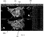
- FIG. 3 is a first view of a three-dimensional cardiac mapping 300a and a second view of a three-dimensional cardiac mapping 300b, according to an embodiment (color omitted).
- the three-dimensional cardiac mapping 300a, 300b comprises low voltage regions 301, which are shaded.
- different colors may be used to indicate different degrees of voltage with respect to the displayed cardiac image and a gradient scale 303 may be displayed for the operator's convenience.
- regions having a voltage measurement of 0.1 mV or less are displayed with a red color indicating a low voltage region and regions having a voltage measurement of 0.5 mV or more are displayed with a pink color indicating a high voltage region with regions having voltage between the low and high voltage thresholds displayed with a color on the gradient scale corresponding to that voltage.
- low voltage regions of a cardiac mapping are associated with diseased or affected tissue.
- an operator such as a physician, lacks the ability to accurately evaluate such low voltage regions. Often, the operator does not know what is happening in a low voltage region. It would be advantageous to identify fractionation signals within low voltage regions to determine what is occurring in the region and whether ablation should be performed at the region.
- FIG. 4 is a diagram of a basket cardiac chamber mapping catheter 40, according to an embodiment.
- the basket cardiac chamber mapping catheter 40 may be used as catheter 14 described above.
- Catheter 40 is similar in design to the basket catheter described in U.S. Pat. No. 6,748,255 , to Fuimaono, et al., which is assigned to the assignees of the present invention and herein incorporated by reference.
- the catheter 40 has multiple ribs, each rib having at multiple electrodes.
- the catheter 40 has 64 unipolar electrodes, and may be configured with up to 7 bipolar pairs per rib.
- rib 42 has unipolar electrodes M1-M8, with bipolar configurations B1-B7.
- the inter-electrode distance may be 4 mm.
- FIG. 5 is a diagram of an example of a spline catheter 46 that may be used as catheter 14 described above.
- the catheter 46 has multiple distal end branches, each branch having several electrodes.
- the example catheter 14 of FIG. 4 has 20 unipolar electrodes, which may be configured as either two or three bipolar pairs per branch.
- branch 47 has a first pair of unipolar electrodes 48, 50 and a second pair of unipolar electrodes 52, 54 (M1-M4). Respective differences between the unipolar electrode pairs are calculated in blocks 56, 58.
- the outputs of blocks 56, 58 (B1, B2) may be associated with one another to constitute a hybrid bipolar electrode configuration, an arrangement referred to herein as a "double bipolar configuration".
- the inter-electrode distances may be 4-4-4 or 2-6-6 mm.
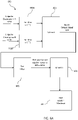
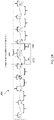
- FIG. 6A is a flow diagram illustrating a process for determining a bipolar activity window 600, according to an embodiment.
- a pre-filter is applied to two unipolar electrograms 601a and 601b.
- the unipolar electrograms 601a and 601b are typically generated from pairs of neighboring electrodes.
- the pre-filter may be configured to remove ventricular far field (VFF) effects.
- VFF ventricular far field
- Far field reduction can be accomplished using the teachings of commonly assigned patent application Ser. No. 14/166,982, entitled Hybrid Bipolar/Unipolar Detection of Activation Wavefront, which is herein incorporated by reference.
- the outputs of the pre-filter blocks 602a and 602b are subtracted in order to determine a bipolar electrogram 604.
- one or more pre-filters are applied to the bipolar electrogram 604.
- a denotch filter may be applied to the first bipolar feature signal 635a and the second bipolar feature signal 635b.
- time intervals comprising a window-of-interest hereinafter referred to as "bipolar activity window" may be determined for the first bipolar feature electrogram 635a and the second bipolar feature electrogram 635b. Different methods may be used to determine the bipolar activity window, as discussed in more detail with respect to FIGs. 7 and 8 .
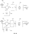
- FIG. 6B illustrates flow diagrams 630a and 630b of the pre-filter process 605, according to an embodiment.
- a sum may be calculated.
- a median filter may be applied to the bipolar electrogram 602a.
- a median filtered signal may be determined and used to correct the electrogram signals such that baseline activities are removed from the electrogram signals.
- the outputs of 621a, 631b are converted to absolute value.
- a first moving average filter may be applied to the output of 631a.
- the moving average filter may take a certain number of samples of input at a time and take the average of those to produce a smoothed output signal referred to as a feature signal. As the length of the filter increases, the smoothness of the output signal increases, whereas the sharp modulations in the data are made increasingly blunt.
- a second moving average filter may be applied to the output of 633b.
- the first moving average filter may be 40ms and the second moving average filter may be 10ms.
- the output of process 630a may be a first bipolar feature 635a and the output of process 630b may be a second bipolar feature 635b.
- FIG. 6C illustrates an example of bipolar electrograms during the prefiltering process described in FIG. 6B .
- Graph 651 illustrates the measured bipolar electrogram.
- Graph 652 illustrates the bipolar electrogram after the baseline correction using the median (632a, 632b in FIG. 6B ).
- Graph 653 illustrates the bipolar electrogram after it has been converted to absolute value (633a, 633b in FIG. 6B ).
- Graph 654 illustrates the resulting first bipolar feature 635a and second bipolar feature 635b after the moving average filter has been applied (634a, 634b in Fig. 6B ).
- FIG. 6D is a flowchart of a denotch filter 640, according to an embodiment, that be used at 606 of Fig. 6A .
- the positive/negative swing couple with the smallest positive swing (swingpMin) or negative swing (swingpMin) is determined.
- swingpMin is less than a predetermined threshold (swingnThr) or if swingnMin is less than a predetermined threshold (swingnThr)
- swingnThr if swingpMin is less than a predetermined threshold (swingnThr)
- swingnThr if swingpMin is greater than or equal to swingnThr, then the process moves to 644, where the process ends.
- the previous swing is compared to the next swing. If the previous negative swing is less than the next negative swing or if the previous positive swing is less than the next positive swing, then the valley is removed at 645 or the peak is removed at 646, respectively.
- FIG. 7 is a diagram illustrating an example process for determining an activity window for a bipolar feature 700, according to an embodiment.
- the process 700 may be used for a bipolar feature signal that is relatively less filtered.
- the process 700 may be used on the first bipolar feature signal 635a for which the moving average filter of 10ms was applied.
- the slope may be calculated to determine if the electrogram is relatively flat (i.e., the slope is under a certain threshold).
- the respective points indicative of when the electrogram is no longer relatively flat may be determined (points 704 and 705).
- These points 704 and 705 may be designated as the start and end of the activity window, respectively.
- the start and end times of the activity window 704, 705 may define a first bipolar feature window.
- FIG. 8 is a diagram illustrating an example process for determining an activity window for a bipolar feature 800, according to an embodiment.
- the process 800 may be used on a bipolar feature that is relatively more filtered.
- the process 800 may be used on the bipolar feature 635b for which the moving average filter of 40ms was applied.
- a current mean 801 and a next mean 802 are calculated. If the current mean 801 is greater than the next mean 802, indicating that the electrogram is still descending, then the process continues to move down the electrogram, until the current mean 801 is less than or equal to the next mean 802, shown as points 804 and 805 in diagram 800. Points 804 and 805 may be designated the start and end of the activity window, respectively.
- the start and end times of the activity window 804, 805 may define a second bipolar feature window.
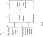
- FIG. 9 is a flow diagram of fusing previously determined activity windows for bipolar features 900 to determine a bipolar activity window, according to an embodiment.
- the start and end times of a first bipolar feature window 901a e.g., 704 and 705 of FIG. 7
- the start and end times of the second bipolar feature window 901b e.g., 804 and 805 of FIG. 8
- the overlap between such windows is 20 percent or greater, the first bipolar feature window 901a and the second bipolar feature window 902b are fused.
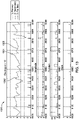
- FIG. 10 is an example visual representation of the process for overlapping two bipolar activity windows, as discussed with respect to FIG. 9 .
- FIG. 10 comprises a first bipolar feature electrogram 1000 with designated activity windows, a second bipolar feature 1010 with designated activity windows, and a combined electrogram 1020 with fused bipolar activity windows.
- the first bipolar feature window 1001 of the first electrogram 1000 and the second bipolar feature activity window 1011 of the second electrogram were determined to have an overlap greater than the fuse threshold.
- the first activity window 1001 and the second activity window 1011 may be combined to create a fused bipolar activity window 1021 in the combined bipolar electrogram 1020.
- a unipolar signal within the window may be analyzed according to the methods described below.
- FIG. 11 is a diagram illustrating an example slope cardiogram (SCG) 1100.
- the corresponding electrogram 1101 is also illustrated.
- the SCG 1100 shows downward (negative) slope amplitude and duration.
- the negative slopes are demarcated as rectangles.
- the width of a rectangle 1110 represents the amplitude of the slope and the length of a rectangle 1111 represents the duration of the slope.
- the duration and amplitude of a negative slope may be used to determine whether a particular slope is a primary slope, secondary slope, far-field, or noise.
- the slope value and amplitude of a negative slope may be used to determine whether a particular slope is a primary slope, secondary slope, far-field, or noise.
- FIG. 12A is a graph 1210 of a negative slope's duration 1211 vs. the negative slope's amplitude 1212, according to an embodiment.
- the negative slope is a primary slope 1213, secondary slope 1214, fair field 1215, or noise 1216.
- the negative slope is identified as noise, regardless of its duration.
- the negative slope may be identified as far-field.
- a negative slope is identified as either noise or far-field, it may not be counted as a slope in further analyses, discussed in more detail below. If a negative slope's amplitude is greater than 0.3mV and its duration is less than 35ms, then it may be identified as a primary slope. If a negative slope amplitude is less than 0.3mV and its duration is less than 35ms, then it may be identified as a secondary slope.
- the thresholds provided above are by way of example only, and other thresholds may be utilized.
- FIG. 12B is a graph 1220 of a negative slope value 1221 vs. the negative slope's amplitude 1222, according to an embodiment.
- the negative slope is a primary slope 1223, secondary slope 1224, fair field 1225, or noise 1226.
- the negative slope is identified as noise, regardless of its slope value.
- the negative slope may be identified as far-field.
- a negative slope is identified as either noise or far-field, it may not be counted as a slope in further analyses, discussed in more detail below. If a negative slope's amplitude is greater than 0.3mV and its slope value is less than 0.2mV/ms, then it may be identified as a primary slope. If a negative slope amplitude is not more than 0.3mV. but not less than .015mV, and its slope value is less than 0.2mV/ms, then it may be identified as a secondary slope.
- the thresholds provided above are by way of example only, and other thresholds may be utilized.
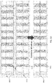
- FIG. 13 is an example unipolar electrogram 1300 with the downward slopes designated as either primary, secondary, or far field.
- the downward slope type may be determined using the methods described above.
- the primary downward slopes 1301, the secondary downward slopes 1302, and the far field downward slopes are designated by respective types of broken lines as indicated in the drawing key.
- artifactual slopes may be removed from a unipolar electrogram.
- small downward notches related to noise may be removed.
- Small downward notches related to noise may be defined as slopes with an amplitude of less than 0.02mV in some embodiments.
- slow downward slopes related to far field potentials may be removed.
- Slow downward slopes related to far field potentials may be defined as slopes less than 0.03 mV/ms and with a duration greater than 25ms in some embodiments.
- small upward slopes embedded in large downward slopes may be removed.
- Upward slopes within large downward slopes with an amplitude of less than 0.05mV and a duration of less than 5ms may be defined as small upward slopes embedded in large downward slopes in some embodiments.
- the thresholds provided above are by way of example only, and other thresholds may be utilized.
- a significant slope may be defined as a slope with an amplitude of greater than 0.05mV, a duration of less than 50ms, a slope of greater than 0.005mV/ms, and a bipolar activity window with greater than 30% overlap and greater than 100 ms.
- FIG. 14 is an example unipolar electrogram 1400 with determined bipolar activity windows.
- the number of complexes of unipolar electrogram 1400 within bipolar activity windows, whose amplitude and peak-to-peak intervals meet certain criteria, is determined.
- the bipolar activity windows are shaded with the amount of shading depending on the number of downward slopes within the window.
- the complex within the bipolar activity window 1401 comprises three slopes. The number of slopes within a bipolar activity window is utilized in the fractionation analysis, as described in more detailed below.
- FIG. 15 is an example unipolar electrogram 1500 illustrating a signalto-noise-ratio (SNR) calculation.
- Unipolar complexes 1501 within bipolar activity windows of the unipolar electrogram 1500 are considered signal and portions of the electrogram outside of the bipolar activity window are designated as noise 1502.
- Rootmean-square (RMS) amplitudes are calculated for respective portions of the electrogram designated as signal and noise.
- the SNR may then be subsequently calculated as a measure of the signal power.
- the SNR may be used in the fractionation analysis, as described in more detailed below.
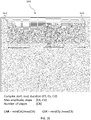
- FIG. 16 is an example complex 1600 of a unipolar electrogram annotated with determined complex level parameters.
- the unipolar electrogram complex 1600 is annotated with the complex start (CS) 1610 (the start of the bipolar activity window), the complex end (CE) 1611 (the end of the bipolar activity window), and the complex duration (CD) 1612.
- the number of slopes (CN) 1620 and respective slope amplitude (CA) and slope value (CV) may be determined.
- These parameters may be used to calculate a complex amplitude ratio (CAR) and a complex slope ratio (CSR).
- CAR may be calculated using Equation 1, below, where min(CA) is the minimum amplitude and max(CA) is the maximum amplitude.
- CSR may be calculated using Equation 2, below, where min(CV) is the minimum slope value and max(CV) is the maximum slope value of the slopes within the activity window.
- the fractionation analysis may take the complex level parameters into account, as discussed in more detail below.
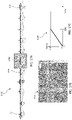
- an example slope cardiogram is analyzed for down slope cross correlation between all complexes C1 to C11 in the same unipolar electrogram 1700.
- the correlation of an ith complex 1701 with a jth complex 1702 may be denoted as Cij., with the value of Cij ranging from 1 to 0.
- Cij value of 1 indicates that the two complexes are identical and a Cij value of 0 indicates that there is no correlation between the two complexes.
- a correlation value greater than 0 to other complexes provides an indication that the present signal is not just noise.
- the correlation may be determined using the morphology of two complexes. In other embodiments, correlation is determined using the timing of slopes within the complexes. The timing of slopes is not affected by respiration, blood flow, etc., which may affect the morphology of a complex.
- FIG. 17B is a cross-correlation matrix 1710 graphically illustrating the correlation of complexes between every possible pair of the 11 complexes C1-C11s in the example unipolar electrogram 1700 of FIG. 17A .
- the higher the correlation value between a pair the darker the box representing the pair is shaded. For example, boxes representing pairs with correlation values 0.85-1 are most darkly shaded.
- the correlation matrix 1710 the complexes of the example unipolar electrogram 1700 are highly correlated.
- CMS complex morphological stability
- XTC is a threshold correlation value.
- the threshold correlation value is 0.8 and if half of the complexes show high correlation, the CMS score is 100, as illustrated in FIG. 17C .
- the fractionation analysis may consider a unipolar electrogram signal's CMS value, as discussed in more detail below.
- LAT local activation time
- the LAT of the electrical activity of at a desired location may be defined in terms of the electrical activity satisfying a predefined condition.
- the predefined condition may comprise a time of occurrence of the largest rapid deflection of the electrogram at the location, and the LAT is assumed to be the time from reference instance to the following onset of the largest rapid deflection of the electrogram of the location.
- the midamplitude or mid-time point may be used as the LAT.
- LAT may be positive or negative.
- Methods for determining the time of occurrence of the largest rapid deflection of the electrogram, and other definitions and conditions for determining the LAT, will be familiar to those skilled in the art, and all such methods, definitions, and conditions are assumed to be comprised within the scope of the present invention.
- FIG. 18 is an example of a unipolar electrogram 1800 where the time intervals of unipolar complexes within bipolar activity windows (indicated with shading) are calculated and compared to each other, according to an embodiment.
- a time interval (I n ) 1801 between the LAT of successive unipolar electrogram complexes within the respective bipolar activity windows may be calculated and compared to a next time interval (I n+1 ) 1802 that follows the time interval 1801.
- a mean time interval (I mean ) 1803 of time intervals of a unipolar electrogram over a predetermined number of intervals that contain time interval (I n ) 1801 and time interval (I n+1 ) 1802 may also be calculated to determine a complex timing stability (CTS) value.
- CTS complex timing stability
- Equation 4 For example, if Equation 4 is satisfied, then the CTS value is 0. If Equation 5a is satisfied, then Equation 5b may be used to calculate the CTS value.
- CTS 100 ⁇ 1 ⁇ abs max I n ⁇ I mean , I n + 1 ⁇ I mean I mean
- the fractionation analysis may take the CTS value into account, as discussed in more detail below.
- FIG. 19 is an example of a unipolar electrogram 1900 illustrating a complex discernibility estimate (CDE) calculation.
- CDE complex discernibility estimate
- Portions indicated with the upper brackets of the unipolar electrogram within a bipolar activity window are complexes, such as complex 1901, and portions of the electrogram outside of the bipolar activity window are designated with lower brackets as isoelectric intervals.
- An isoelectric interval Iso 1 1902 may be compared to a next isoelectric interval Iso 2 1903. If the isoelectric intervals 1902, 1903 surrounding the complex 1901 are highly comparable to the signal of complex 1901, then the complex 1901 has a low CDE, which is not desirable.
- CDE using the root mean square (RMS) amplitudes of the electrogram portions per Equation 6. The fractionation analysis may take the CDE value into account, as discussed in more detail below.
- CDE 100 * RMS Signal of Complex / RMS Signal of Complex + Iso 1 + Iso 2
- the processor of the computing device 22 may be configured use the received and/or location signals to calculate measurement changes in the location of the catheter 14 during the collection of signals. Measurement computations may account for respiratory movement when measuring changes in the location of the catheter 14 sensors. Position stability refers to the measurement of changes in the location of the distal end of the catheter 14 during the collection of signals.
- the fractionation analysis may require that the variation of the location of the catheter over a defined time window be not greater than a predefined maximum distance. The variation may be measured in terms of standard deviation about the mean position during the defined time window.
- a Tissue Proximity Indicator (TPI) value can indicate whether a catheter was in proximity to the tissue of interest when a signal was recorded.
- the TPI may be positive or negative and may indicate whether the catheter is in proximity to tissue, not in proximity to tissue, or if it is unknown. Generally, for accuracy, signals taken when the catheter is in contact with or in proximity to tissue are preferable. Additionally, if the distal end of the catheter 14 is touching the tissue, the signal may indicate characteristics of the tissue.
- the fractionation analysis may or may not take a TPI value of a signal into account. For example, if the TPI indicates that a signal was not recorded within a certain proximity, then the analysis may not use that signal in the fractionation analysis.
- slope ensemble statistics may be calculated from slope characteristics per complex, per potential type. For example, if there is a single potential within a bipolar activity window of a unipolar electrogram, the amplitude and slope may be determined. If there is a double potential, a fractionated potential (three deflections) or a highly fractionated potential (long and more than three deflections) within a bipolar activity window, the mean amplitude and slope may be determined. In some complexes, there may be a slope that does not meet a minimum amplitude or other characteristic within a complex so that it is not counted in determining potential type. For example, a complex having three slopes, where one slope is not of a predetermined minimum amplitude, that complex can be considered as having a double potential.
- the slope amplitude and value ensemble statistics may be sorted from lowest to highest to create scales AREST and VREST.
- the rating of a maximum amplitude AREST(CA) and slope VREST(CV) may be determined per complex in sorted lists by finding the index >REST(AREST,VREST) divided by the number of entries in the list per potential type.
- Slope amplitude and slope value may be rated based on potential dedicated scales.
- the score of amplitude may be determined per complex in ASCALE(CA) and VSCALE(CV) within the dedicated scales, by finding an index divided by the number of entries in the list per potential type.
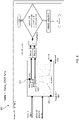
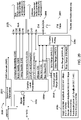
- FIG. 20 is a flow chart diagram of an example fractionation analysis 2000.
- the analysis 2000 makes a quality of annotation (QoA) measurement and evidence value (EVI) measurement.
- QoA quality of annotation
- EVI evidence value
- the QoA is a level of confidence provided per annotation.
- the QoA may be based on complex parameters within a recording and provided per complex type.
- the EVI is annotation evidence provided per complex (bipolar activity window).
- the evidence annotation value is based on slope parameters within a complex and provided per complex type.
- one or more signal level parameters of a unipolar electrogram are determined.
- the one or more signal level parameters may include, but is not limited to, an SNR estimate.
- the SNR estimate may be performed according to the methods described above.
- a bipolar activity window of a bipolar electrogram is determined.
- the bipolar activity window may be determined using the methods described above.
- one or more complex level parameters are determined based on the bipolar activity window.
- the one or more complex parameters may include complex discernibility (CDE), complex morphological stability (CMS), complex timing stability (CTS), bipolar activity window start (CS), bipolar activity window end (CE), and bipolar activity window duration (CD), minimum/maximum amplitude ratio (CAR), minimum/maximum slope ratio (CVR), number of slopes (CN), maximum slope amplitude (CA), and maximum slope (CV).
- CDE complex discernibility
- CMS complex morphological stability
- CTS complex timing stability
- CS bipolar activity window start
- CE bipolar activity window end
- CD bipolar activity window duration
- CAR minimum/maximum amplitude ratio
- CVR minimum/maximum slope ratio
- CN minimum/maximum slope ratio
- CA maximum slope amplitude
- CV maximum slope
- a unipolar/bipolar slope overlap (UBO) parameter may also be determined.
- the complex level parameters may be determined using the methods described above.
- the number of slopes (CN), maximum amplitude (CA), and maximum slope (CV) may be used to determine one or more complex level range rating statistics.
- the one or more complex level range rating statistics may include, but are not limited to a relative slope amplitude range (AREST) and slope value range (VREST).
- the relative slope amplitude range (AREST) and slope value range (VREST) may be determined using the methods described above.
- an absolute slope amplitude range (ASCALE) and slope value range (VSCALE) relative to AREST and VREST may be determined. In the embodiment illustrated in FIG.
- example potential dedicated scales for slope amplitude and slope value for a single potential, double potential, and fractionated potential are shown with highly fractionated potential included in the listing for fractionated potential.
- the example dedicated scales are also provided below in Table 1 below. Table 1 Amplitude Slope Single potential 0:0.5:5 mV 0:0.1:1 mV/ms Double potential 0:0.3:3 mV 0:0.05:0.5 mV/ms Fractionated potential 0:0.1:1 mV Slope 0:0.02:0.2 mV/ms
- complex level rating scores may be determined.
- the complex level rating scores may be determined using the methods described above. For example, in some embodiments, the rating of a maximum amplitude AREST(CA) and slope SREST(CV) may be determined per complex in sorted lists by finding the index >REST(AREST,VREST) divided by the number of entries in the list per potential type.
- the QoA is then determined based on one or more complex level parameters and/or complex level ratings at 2060, as discussed in more detail with respect to FIG. 21 .
- the evidence annotation measurement EVI is determined using an evidence table 2081, as discussed in more detailed with respect to FIG. 22 .
- FIG. 21 is a diagram 2100 illustrating parameters 2101 and weights 2102 for a QoA measurement, according to an embodiment.
- the QoA measurement may be the weighted sum of two or more following parameters: (1) ASCALE 2101a; (2) VSCALE 2101b; (3) AREST 2101c; (4) VREST 2101d; (5) complex amplitude ratio (CAR) 2101e; (6) complex slope ratio (CVR) 2101f; (7) unipolar/bipolar slope overlap (UBO) 2101g; (8) complex morphological stability (CMS) 2101h; (9) complex timing stability (CTS) 2101i; and (10) complex discernibility estimate (CDE) 2101j.
- this list of parameters is not exhaustive, and other parameters may be used in the QoA measurement.
- the weights used in the QoA measurement may be defined per potential type.
- the weight may be defined depending on whether the potential type is single 2110, double 2120, or fractionated 2130.
- fractionated value is used for highly fractionated types as well.
- N is the number of parameters
- Pi is the value of the ith of the N parameters listed above
- w p,i is the weight value for the ith parameter depending on potential type (p) from the table of Fig. 21 .
- FIG. 22 is an example evidence table 2200 for the evidence annotation measurement EVI as a percentage value, according to an embodiment.
- the evidence table may comprise a plurality of classifications 2110 based one or more ECG complex parameters.
- the classifications 2110 are based on ECG complex amplitude scale, complex width, and amplitude ratio of a signal. For example, a complex with an amplitude scale of less than or equal to 20, a complex width of greater than 60, and amplitude ratio of greater than 10 may be classified as Group 19 (2110a).
- An evidence score may then be coded in the table based on the classification, number of slopes (one 2120a, two 2120b, three 2120c, or more than three 2120d), and potential type (i.e., single 2130a, double 2130b, fractionated 2130c or highly fractionated (fractionate+) 2130d). For example, if complex classified as Group 19 has more than three slopes and was identified as a highly fractionated potential, then the complex has an evidence score of 90 (2140) (if identified as a fractionated potential, then the complex has an evidence score of 80).
- the QoA and EVI measurements may be used to determine a final score for a complex.
- a modulating factor M is first calculated based on the QoA and EVI.
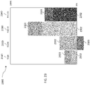
- FIG. 23 is a graph 2300 illustrating a combined evidence annotation measurement (EVI) and modulating factor M for a single potential 2310, a double potential 2320, a fractionated potential (three deflections) 2330 and a highly fractionated potential (long and more than three deflections) 2340, according to an embodiment.
- the final score may be expressed as a percentage, with 100 percent being the highest possible score. The final score may be used to determine whether a complex is a fractionated complex.
- a unipolar electrogram having a predetermined number of successive complexes with final scores of 90% or higher may be identified as a fractionated signal.
- unipolar electrogram complexes with an EVI value of 90% from the Fig. 22 table and a QoA value of at least 50% as well as unipolar electrogram complexes with an EVI value of 80% from the Fig. 22 table and a QoA value of at least 75% meet this final score threshold of 90% or higher.
- Fractionated potentials may occur as a result of slow propagation of activation waves, travelling across areas of diseased tissue that may show an erratic (e.g. zig-zag) type of activation slowing down propagation compared to straightforward fast propagation in healthy tissue (structural fractionation).
- double and fractionated potential may occur as a result of multiple dissociated waves separated by functional lines of block that also results in complex activation patterns and associated fractionated potentials (functional fractionation).
- functional fractionation the latter, in general, does not persist very long, so persistent fractionation (e.g. over at least several beats) points to the structural nature of fractionation.
- LATs local activation times
- a cardiac tissue region that is highly correlated with fractionated signals may be determined by the apparatus 10 as an arrhythmogenic site for treatment via catheter ablation.
- unipolar electrograms representing an area of study such as the entirety of a left atrium may be obtained from the catheter 47 and scored by computing device 22 based on the above.
- the unipolar electrograms scored as fractionated signals are evaluated to determine if there is an atrial tissue area, represented by at least several (e.g. ⁇ 3) replicated fractionated unipolar potentials.
- An atrial tissue area meeting having a predetermined number of unipolar electrograms that meet such criteria, for example, at least three, is then determined by the processor of the computing device 22 to be an atrial arrhythmogenic site for potential ablation treatment.
- the area of study with the determined atrial arrhythmogenic site can then be displayed on the display 29 to assist the operator 16 in performing an ablation treatment.
- unipolar electrograms representing the entirety of a heart chamber can be obtained and scored to determine the existence of a cardiac tissue area within the cardiac region of study that meets the above criteria to be determined to be an arrhythmogenic site for potential ablation treatment.
- the methods described herein may comprise algorithms that can be utilized by a skilled software engineer to generate the requisite step-by-step computer codes for implementation of the overall method in a computer system (e.g., a generalpurpose computer or a special purpose computer such as the Carto system).
- a computer system e.g., a generalpurpose computer or a special purpose computer such as the Carto system.
- the corresponding electrograms, calculations and results may be displayed on a display, such as a graphical user interface.
Landscapes
- Health & Medical Sciences (AREA)
- Life Sciences & Earth Sciences (AREA)
- Engineering & Computer Science (AREA)
- Surgery (AREA)
- Physics & Mathematics (AREA)
- Public Health (AREA)
- General Health & Medical Sciences (AREA)
- Biomedical Technology (AREA)
- Heart & Thoracic Surgery (AREA)
- Medical Informatics (AREA)
- Molecular Biology (AREA)
- Veterinary Medicine (AREA)
- Animal Behavior & Ethology (AREA)
- Cardiology (AREA)
- Pathology (AREA)
- Biophysics (AREA)
- Physiology (AREA)
- Signal Processing (AREA)
- Artificial Intelligence (AREA)
- Computer Vision & Pattern Recognition (AREA)
- Psychiatry (AREA)
- Plasma & Fusion (AREA)
- Nuclear Medicine, Radiotherapy & Molecular Imaging (AREA)
- Otolaryngology (AREA)
- Measurement And Recording Of Electrical Phenomena And Electrical Characteristics Of The Living Body (AREA)
- Surgical Instruments (AREA)
Applications Claiming Priority (2)
| Application Number | Priority Date | Filing Date | Title |
|---|---|---|---|
| US202163189957P | 2021-05-18 | 2021-05-18 | |
| US17/706,223 US20220369991A1 (en) | 2021-05-18 | 2022-03-28 | Medical apparatus for diagnostic and site determination of cardiac arrhythmias and methods |
Publications (3)
| Publication Number | Publication Date |
|---|---|
| EP4091547A1 true EP4091547A1 (de) | 2022-11-23 |
| EP4091547B1 EP4091547B1 (de) | 2023-11-22 |
| EP4091547C0 EP4091547C0 (de) | 2023-11-22 |
Family
ID=81748776
Family Applications (1)
| Application Number | Title | Priority Date | Filing Date |
|---|---|---|---|
| EP22173737.2A Active EP4091547B1 (de) | 2021-05-18 | 2022-05-17 | Medizinisches gerät zur diagnose und ortung von herzarrhythmien |
Country Status (5)
| Country | Link |
|---|---|
| US (1) | US20220369991A1 (de) |
| EP (1) | EP4091547B1 (de) |
| JP (1) | JP7844791B2 (de) |
| CN (1) | CN115363600A (de) |
| IL (1) | IL292949B2 (de) |
Families Citing this family (3)
| Publication number | Priority date | Publication date | Assignee | Title |
|---|---|---|---|---|
| US20220068479A1 (en) * | 2020-08-26 | 2022-03-03 | Biosense Webster (Israel) Ltd. | Separating abnormal heart activities into different classes |
| US12551658B2 (en) | 2022-03-25 | 2026-02-17 | St. Jude Medical, Cardiology Division, Inc. | Steerable introducer with slide block divider |
| US20250185973A1 (en) | 2023-12-12 | 2025-06-12 | Biosense Webster (Israel) Ltd. | Gui to visually connect features identified in electroanatomical (ea) map to ecg signals |
Citations (8)
| Publication number | Priority date | Publication date | Assignee | Title |
|---|---|---|---|---|
| US6748255B2 (en) | 2001-12-14 | 2004-06-08 | Biosense Webster, Inc. | Basket catheter with multiple location sensors |
| US6814733B2 (en) | 2002-01-31 | 2004-11-09 | Biosense, Inc. | Radio frequency pulmonary vein isolation |
| US6961602B2 (en) | 2001-12-31 | 2005-11-01 | Biosense Webster, Inc. | Catheter having multiple spines each having electrical mapping and location sensing capabilities |
| US6997924B2 (en) | 2002-09-17 | 2006-02-14 | Biosense Inc. | Laser pulmonary vein isolation |
| US7156816B2 (en) | 2002-11-26 | 2007-01-02 | Biosense, Inc. | Ultrasound pulmonary vein isolation |
| US7536218B2 (en) | 2005-07-15 | 2009-05-19 | Biosense Webster, Inc. | Hybrid magnetic-based and impedance-based position sensing |
| US7756576B2 (en) | 2005-08-26 | 2010-07-13 | Biosense Webster, Inc. | Position sensing and detection of skin impedance |
| US20150208942A1 (en) * | 2014-01-29 | 2015-07-30 | Biosense Webster (Israel) Ltd. | Double bipolar configuration for atrial fibrillation annotation |
Family Cites Families (5)
| Publication number | Priority date | Publication date | Assignee | Title |
|---|---|---|---|---|
| US8948837B2 (en) | 2011-01-13 | 2015-02-03 | Rhythmia Medical, Inc. | Electroanatomical mapping |
| US9031642B2 (en) * | 2013-02-21 | 2015-05-12 | Medtronic, Inc. | Methods for simultaneous cardiac substrate mapping using spatial correlation maps between neighboring unipolar electrograms |
| WO2015171492A1 (en) * | 2014-05-05 | 2015-11-12 | Cardionxt, Inc. | Methods, systems, and apparatus for identification, characterization, and treatment of rotors associated with fibrillation |
| US9649046B2 (en) | 2014-08-12 | 2017-05-16 | Biosense Webster (Israel) Ltd | Line of block detection |
| US11006887B2 (en) * | 2016-01-14 | 2021-05-18 | Biosense Webster (Israel) Ltd. | Region of interest focal source detection using comparisons of R-S wave magnitudes and LATs of RS complexes |
-
2022
- 2022-03-28 US US17/706,223 patent/US20220369991A1/en active Pending
- 2022-05-11 IL IL292949A patent/IL292949B2/en unknown
- 2022-05-17 JP JP2022080714A patent/JP7844791B2/ja active Active
- 2022-05-17 EP EP22173737.2A patent/EP4091547B1/de active Active
- 2022-05-18 CN CN202210539857.5A patent/CN115363600A/zh active Pending
Patent Citations (8)
| Publication number | Priority date | Publication date | Assignee | Title |
|---|---|---|---|---|
| US6748255B2 (en) | 2001-12-14 | 2004-06-08 | Biosense Webster, Inc. | Basket catheter with multiple location sensors |
| US6961602B2 (en) | 2001-12-31 | 2005-11-01 | Biosense Webster, Inc. | Catheter having multiple spines each having electrical mapping and location sensing capabilities |
| US6814733B2 (en) | 2002-01-31 | 2004-11-09 | Biosense, Inc. | Radio frequency pulmonary vein isolation |
| US6997924B2 (en) | 2002-09-17 | 2006-02-14 | Biosense Inc. | Laser pulmonary vein isolation |
| US7156816B2 (en) | 2002-11-26 | 2007-01-02 | Biosense, Inc. | Ultrasound pulmonary vein isolation |
| US7536218B2 (en) | 2005-07-15 | 2009-05-19 | Biosense Webster, Inc. | Hybrid magnetic-based and impedance-based position sensing |
| US7756576B2 (en) | 2005-08-26 | 2010-07-13 | Biosense Webster, Inc. | Position sensing and detection of skin impedance |
| US20150208942A1 (en) * | 2014-01-29 | 2015-07-30 | Biosense Webster (Israel) Ltd. | Double bipolar configuration for atrial fibrillation annotation |
Non-Patent Citations (1)
| Title |
|---|
| MUNOZ ET AL.: "Three-Dimensional Mapping of Cardiac Arrhythmias - What Do the Colors Really Mean", CIRCULATION: ARRHYTHMIA AND ELECTROPHYSIOLOGY, vol. 3, 1 December 2010 (2010-12-01), XP055253861, DOI: 10.1161/CIRCEP.110.960161 |
Also Published As
| Publication number | Publication date |
|---|---|
| IL292949B2 (en) | 2026-01-01 |
| JP7844791B2 (ja) | 2026-04-14 |
| CN115363600A (zh) | 2022-11-22 |
| US20220369991A1 (en) | 2022-11-24 |
| IL292949A (en) | 2022-12-01 |
| IL292949B1 (en) | 2025-09-01 |
| JP2022177820A (ja) | 2022-12-01 |
| EP4091547B1 (de) | 2023-11-22 |
| EP4091547C0 (de) | 2023-11-22 |
Similar Documents
| Publication | Publication Date | Title |
|---|---|---|
| EP3878365B1 (de) | Einstellung von annotationspunkten in echtzeit | |
| US10004413B2 (en) | Signal analysis related to treatment sites | |
| US10863915B2 (en) | Annotation histogram | |
| JP7630913B2 (ja) | 心不整脈治療のための目標駆動ワークフロー | |
| EP3102102B1 (de) | Integrierte analyse von elektrophysiologischen daten | |
| EP4091547B1 (de) | Medizinisches gerät zur diagnose und ortung von herzarrhythmien | |
| EP3366207A1 (de) | Hervorhebung eines elektrodenbildes gemäss einem elektrodensignal | |
| EP3139828B1 (de) | Nachweis von pulmonarvenenisolation | |
| EP3705037A1 (de) | Mittelfeldsignalextraktion | |
| EP3831304B1 (de) | Intrakardialer musterabgleich | |
| CN120814830A (zh) | 用于辅助标测心律异常的计算机实现的方法和系统 | |
| JP7772298B2 (ja) | 心臓マッピング中の拒絶フィルタのリアルタイム評価 | |
| WO2023089494A1 (en) | Algorithm for optimal beat selection | |
| US11596341B2 (en) | Systems and methods for identifying split activation histograms in cardiac mapping procedures | |
| EP3669767B1 (de) | Visualisierung verschiedener herzrhythmen unter verwendung verschiedener bildpunktanzeigen | |
| US12588854B2 (en) | Algorithm for optimal beat selection | |
| CN110520038B (zh) | 心律失常驱动器的连通性分析 | |
| JP7669144B2 (ja) | ユニポーラ信号及びバイポーラ信号を使用した心室活動の検出 | |
| CN114652325A (zh) | 包括局部异常心室激活(lava)信号的晚电位的注释 |
Legal Events
| Date | Code | Title | Description |
|---|---|---|---|
| PUAI | Public reference made under article 153(3) epc to a published international application that has entered the european phase |
Free format text: ORIGINAL CODE: 0009012 |
|
| STAA | Information on the status of an ep patent application or granted ep patent |
Free format text: STATUS: THE APPLICATION HAS BEEN PUBLISHED |
|
| AK | Designated contracting states |
Kind code of ref document: A1 Designated state(s): AL AT BE BG CH CY CZ DE DK EE ES FI FR GB GR HR HU IE IS IT LI LT LU LV MC MK MT NL NO PL PT RO RS SE SI SK SM TR |
|
| STAA | Information on the status of an ep patent application or granted ep patent |
Free format text: STATUS: REQUEST FOR EXAMINATION WAS MADE |
|
| 17P | Request for examination filed |
Effective date: 20230515 |
|
| RBV | Designated contracting states (corrected) |
Designated state(s): AL AT BE BG CH CY CZ DE DK EE ES FI FR GB GR HR HU IE IS IT LI LT LU LV MC MK MT NL NO PL PT RO RS SE SI SK SM TR |
|
| RIC1 | Information provided on ipc code assigned before grant |
Ipc: A61B 5/00 20060101ALI20230524BHEP Ipc: A61B 5/367 20210101ALI20230524BHEP Ipc: A61B 5/308 20210101ALI20230524BHEP Ipc: A61B 5/287 20210101AFI20230524BHEP |
|
| GRAP | Despatch of communication of intention to grant a patent |
Free format text: ORIGINAL CODE: EPIDOSNIGR1 |
|
| STAA | Information on the status of an ep patent application or granted ep patent |
Free format text: STATUS: GRANT OF PATENT IS INTENDED |
|
| INTG | Intention to grant announced |
Effective date: 20230717 |
|
| GRAS | Grant fee paid |
Free format text: ORIGINAL CODE: EPIDOSNIGR3 |
|
| GRAA | (expected) grant |
Free format text: ORIGINAL CODE: 0009210 |
|
| STAA | Information on the status of an ep patent application or granted ep patent |
Free format text: STATUS: THE PATENT HAS BEEN GRANTED |
|
| AK | Designated contracting states |
Kind code of ref document: B1 Designated state(s): AL AT BE BG CH CY CZ DE DK EE ES FI FR GB GR HR HU IE IS IT LI LT LU LV MC MK MT NL NO PL PT RO RS SE SI SK SM TR |
|
| REG | Reference to a national code |
Ref country code: GB Ref legal event code: FG4D |
|
| REG | Reference to a national code |
Ref country code: CH Ref legal event code: EP |
|
| REG | Reference to a national code |
Ref country code: DE Ref legal event code: R096 Ref document number: 602022001068 Country of ref document: DE |
|
| REG | Reference to a national code |
Ref country code: IE Ref legal event code: FG4D |
|
| U01 | Request for unitary effect filed |
Effective date: 20231206 |
|
| U07 | Unitary effect registered |
Designated state(s): AT BE BG DE DK EE FI FR IT LT LU LV MT NL PT SE SI Effective date: 20231214 |
|
| PG25 | Lapsed in a contracting state [announced via postgrant information from national office to epo] |
Ref country code: GR Free format text: LAPSE BECAUSE OF FAILURE TO SUBMIT A TRANSLATION OF THE DESCRIPTION OR TO PAY THE FEE WITHIN THE PRESCRIBED TIME-LIMIT Effective date: 20240223 |
|
| PG25 | Lapsed in a contracting state [announced via postgrant information from national office to epo] |
Ref country code: IS Free format text: LAPSE BECAUSE OF FAILURE TO SUBMIT A TRANSLATION OF THE DESCRIPTION OR TO PAY THE FEE WITHIN THE PRESCRIBED TIME-LIMIT Effective date: 20240322 |
|
| PG25 | Lapsed in a contracting state [announced via postgrant information from national office to epo] |
Ref country code: ES Free format text: LAPSE BECAUSE OF FAILURE TO SUBMIT A TRANSLATION OF THE DESCRIPTION OR TO PAY THE FEE WITHIN THE PRESCRIBED TIME-LIMIT Effective date: 20231122 |
|
| PG25 | Lapsed in a contracting state [announced via postgrant information from national office to epo] |
Ref country code: IS Free format text: LAPSE BECAUSE OF FAILURE TO SUBMIT A TRANSLATION OF THE DESCRIPTION OR TO PAY THE FEE WITHIN THE PRESCRIBED TIME-LIMIT Effective date: 20240322 Ref country code: GR Free format text: LAPSE BECAUSE OF FAILURE TO SUBMIT A TRANSLATION OF THE DESCRIPTION OR TO PAY THE FEE WITHIN THE PRESCRIBED TIME-LIMIT Effective date: 20240223 Ref country code: ES Free format text: LAPSE BECAUSE OF FAILURE TO SUBMIT A TRANSLATION OF THE DESCRIPTION OR TO PAY THE FEE WITHIN THE PRESCRIBED TIME-LIMIT Effective date: 20231122 |
|
| U20 | Renewal fee for the european patent with unitary effect paid |
Year of fee payment: 3 Effective date: 20240408 |
|
| PG25 | Lapsed in a contracting state [announced via postgrant information from national office to epo] |
Ref country code: RS Free format text: LAPSE BECAUSE OF FAILURE TO SUBMIT A TRANSLATION OF THE DESCRIPTION OR TO PAY THE FEE WITHIN THE PRESCRIBED TIME-LIMIT Effective date: 20231122 Ref country code: PL Free format text: LAPSE BECAUSE OF FAILURE TO SUBMIT A TRANSLATION OF THE DESCRIPTION OR TO PAY THE FEE WITHIN THE PRESCRIBED TIME-LIMIT Effective date: 20231122 Ref country code: NO Free format text: LAPSE BECAUSE OF FAILURE TO SUBMIT A TRANSLATION OF THE DESCRIPTION OR TO PAY THE FEE WITHIN THE PRESCRIBED TIME-LIMIT Effective date: 20240222 Ref country code: HR Free format text: LAPSE BECAUSE OF FAILURE TO SUBMIT A TRANSLATION OF THE DESCRIPTION OR TO PAY THE FEE WITHIN THE PRESCRIBED TIME-LIMIT Effective date: 20231122 |
|
| PG25 | Lapsed in a contracting state [announced via postgrant information from national office to epo] |
Ref country code: CZ Free format text: LAPSE BECAUSE OF FAILURE TO SUBMIT A TRANSLATION OF THE DESCRIPTION OR TO PAY THE FEE WITHIN THE PRESCRIBED TIME-LIMIT Effective date: 20231122 |
|
| PG25 | Lapsed in a contracting state [announced via postgrant information from national office to epo] |
Ref country code: SK Free format text: LAPSE BECAUSE OF FAILURE TO SUBMIT A TRANSLATION OF THE DESCRIPTION OR TO PAY THE FEE WITHIN THE PRESCRIBED TIME-LIMIT Effective date: 20231122 |
|
| PG25 | Lapsed in a contracting state [announced via postgrant information from national office to epo] |
Ref country code: SM Free format text: LAPSE BECAUSE OF FAILURE TO SUBMIT A TRANSLATION OF THE DESCRIPTION OR TO PAY THE FEE WITHIN THE PRESCRIBED TIME-LIMIT Effective date: 20231122 Ref country code: SK Free format text: LAPSE BECAUSE OF FAILURE TO SUBMIT A TRANSLATION OF THE DESCRIPTION OR TO PAY THE FEE WITHIN THE PRESCRIBED TIME-LIMIT Effective date: 20231122 Ref country code: RO Free format text: LAPSE BECAUSE OF FAILURE TO SUBMIT A TRANSLATION OF THE DESCRIPTION OR TO PAY THE FEE WITHIN THE PRESCRIBED TIME-LIMIT Effective date: 20231122 Ref country code: CZ Free format text: LAPSE BECAUSE OF FAILURE TO SUBMIT A TRANSLATION OF THE DESCRIPTION OR TO PAY THE FEE WITHIN THE PRESCRIBED TIME-LIMIT Effective date: 20231122 |
|
| REG | Reference to a national code |
Ref country code: DE Ref legal event code: R097 Ref document number: 602022001068 Country of ref document: DE |
|
| PLBE | No opposition filed within time limit |
Free format text: ORIGINAL CODE: 0009261 |
|
| STAA | Information on the status of an ep patent application or granted ep patent |
Free format text: STATUS: NO OPPOSITION FILED WITHIN TIME LIMIT |
|
| 26N | No opposition filed |
Effective date: 20240823 |
|
| PG25 | Lapsed in a contracting state [announced via postgrant information from national office to epo] |
Ref country code: MC Free format text: LAPSE BECAUSE OF FAILURE TO SUBMIT A TRANSLATION OF THE DESCRIPTION OR TO PAY THE FEE WITHIN THE PRESCRIBED TIME-LIMIT Effective date: 20231122 |
|
| PG25 | Lapsed in a contracting state [announced via postgrant information from national office to epo] |
Ref country code: MC Free format text: LAPSE BECAUSE OF FAILURE TO SUBMIT A TRANSLATION OF THE DESCRIPTION OR TO PAY THE FEE WITHIN THE PRESCRIBED TIME-LIMIT Effective date: 20231122 |
|
| PG25 | Lapsed in a contracting state [announced via postgrant information from national office to epo] |
Ref country code: IE Free format text: LAPSE BECAUSE OF NON-PAYMENT OF DUE FEES Effective date: 20240517 |
|
| U20 | Renewal fee for the european patent with unitary effect paid |
Year of fee payment: 4 Effective date: 20250407 |
|
| PG25 | Lapsed in a contracting state [announced via postgrant information from national office to epo] |
Ref country code: CY Free format text: LAPSE BECAUSE OF FAILURE TO SUBMIT A TRANSLATION OF THE DESCRIPTION OR TO PAY THE FEE WITHIN THE PRESCRIBED TIME-LIMIT; INVALID AB INITIO Effective date: 20220517 |
|
| PG25 | Lapsed in a contracting state [announced via postgrant information from national office to epo] |
Ref country code: HU Free format text: LAPSE BECAUSE OF FAILURE TO SUBMIT A TRANSLATION OF THE DESCRIPTION OR TO PAY THE FEE WITHIN THE PRESCRIBED TIME-LIMIT; INVALID AB INITIO Effective date: 20220517 |
|
| REG | Reference to a national code |
Ref country code: CH Ref legal event code: H13 Free format text: ST27 STATUS EVENT CODE: U-0-0-H10-H13 (AS PROVIDED BY THE NATIONAL OFFICE) Effective date: 20251223 |
|
| PG25 | Lapsed in a contracting state [announced via postgrant information from national office to epo] |
Ref country code: CH Free format text: LAPSE BECAUSE OF NON-PAYMENT OF DUE FEES Effective date: 20250531 |
|
| PGFP | Annual fee paid to national office [announced via postgrant information from national office to epo] |
Ref country code: GB Payment date: 20260324 Year of fee payment: 5 |