EP4091568A2 - Registriersonde zur verbesserten erfassung von informationen - Google Patents
Registriersonde zur verbesserten erfassung von informationen Download PDFInfo
- Publication number
- EP4091568A2 EP4091568A2 EP22174259.6A EP22174259A EP4091568A2 EP 4091568 A2 EP4091568 A2 EP 4091568A2 EP 22174259 A EP22174259 A EP 22174259A EP 4091568 A2 EP4091568 A2 EP 4091568A2
- Authority
- EP
- European Patent Office
- Prior art keywords
- probe
- navigation system
- input
- igs navigation
- igs
- Prior art date
- Legal status (The legal status is an assumption and is not a legal conclusion. Google has not performed a legal analysis and makes no representation as to the accuracy of the status listed.)
- Granted
Links
Images



Classifications
-
- A—HUMAN NECESSITIES
- A61—MEDICAL OR VETERINARY SCIENCE; HYGIENE
- A61B—DIAGNOSIS; SURGERY; IDENTIFICATION
- A61B34/00—Computer-aided surgery; Manipulators or robots specially adapted for use in surgery
- A61B34/20—Surgical navigation systems; Devices for tracking or guiding surgical instruments, e.g. for frameless stereotaxis
-
- A—HUMAN NECESSITIES
- A61—MEDICAL OR VETERINARY SCIENCE; HYGIENE
- A61B—DIAGNOSIS; SURGERY; IDENTIFICATION
- A61B34/00—Computer-aided surgery; Manipulators or robots specially adapted for use in surgery
- A61B34/10—Computer-aided planning, simulation or modelling of surgical operations
-
- A—HUMAN NECESSITIES
- A61—MEDICAL OR VETERINARY SCIENCE; HYGIENE
- A61B—DIAGNOSIS; SURGERY; IDENTIFICATION
- A61B34/00—Computer-aided surgery; Manipulators or robots specially adapted for use in surgery
- A61B34/25—User interfaces for surgical systems
-
- G—PHYSICS
- G06—COMPUTING OR CALCULATING; COUNTING
- G06F—ELECTRIC DIGITAL DATA PROCESSING
- G06F1/00—Details not covered by groups G06F3/00 - G06F13/00 and G06F21/00
- G06F1/16—Constructional details or arrangements
- G06F1/1613—Constructional details or arrangements for portable computers
- G06F1/1633—Constructional details or arrangements of portable computers not specific to the type of enclosures covered by groups G06F1/1615 - G06F1/1626
- G06F1/1684—Constructional details or arrangements related to integrated I/O peripherals not covered by groups G06F1/1635 - G06F1/1675
- G06F1/1694—Constructional details or arrangements related to integrated I/O peripherals not covered by groups G06F1/1635 - G06F1/1675 the I/O peripheral being a single or a set of motion sensors for pointer control or gesture input obtained by sensing movements of the portable computer
-
- G—PHYSICS
- G06—COMPUTING OR CALCULATING; COUNTING
- G06F—ELECTRIC DIGITAL DATA PROCESSING
- G06F3/00—Input arrangements for transferring data to be processed into a form capable of being handled by the computer; Output arrangements for transferring data from processing unit to output unit, e.g. interface arrangements
- G06F3/01—Input arrangements or combined input and output arrangements for interaction between user and computer
- G06F3/048—Interaction techniques based on graphical user interfaces [GUI]
- G06F3/0481—Interaction techniques based on graphical user interfaces [GUI] based on specific properties of the displayed interaction object or a metaphor-based environment, e.g. interaction with desktop elements like windows or icons, or assisted by a cursor's changing behaviour or appearance
-
- G—PHYSICS
- G06—COMPUTING OR CALCULATING; COUNTING
- G06F—ELECTRIC DIGITAL DATA PROCESSING
- G06F3/00—Input arrangements for transferring data to be processed into a form capable of being handled by the computer; Output arrangements for transferring data from processing unit to output unit, e.g. interface arrangements
- G06F3/01—Input arrangements or combined input and output arrangements for interaction between user and computer
- G06F3/048—Interaction techniques based on graphical user interfaces [GUI]
- G06F3/0484—Interaction techniques based on graphical user interfaces [GUI] for the control of specific functions or operations, e.g. selecting or manipulating an object, an image or a displayed text element, setting a parameter value or selecting a range
- G06F3/04842—Selection of displayed objects or displayed text elements
-
- G—PHYSICS
- G06—COMPUTING OR CALCULATING; COUNTING
- G06F—ELECTRIC DIGITAL DATA PROCESSING
- G06F3/00—Input arrangements for transferring data to be processed into a form capable of being handled by the computer; Output arrangements for transferring data from processing unit to output unit, e.g. interface arrangements
- G06F3/01—Input arrangements or combined input and output arrangements for interaction between user and computer
- G06F3/048—Interaction techniques based on graphical user interfaces [GUI]
- G06F3/0487—Interaction techniques based on graphical user interfaces [GUI] using specific features provided by the input device, e.g. functions controlled by the rotation of a mouse with dual sensing arrangements, or of the nature of the input device, e.g. tap gestures based on pressure sensed by a digitiser
- G06F3/0488—Interaction techniques based on graphical user interfaces [GUI] using specific features provided by the input device, e.g. functions controlled by the rotation of a mouse with dual sensing arrangements, or of the nature of the input device, e.g. tap gestures based on pressure sensed by a digitiser using a touch-screen or digitiser, e.g. input of commands through traced gestures
- G06F3/04883—Interaction techniques based on graphical user interfaces [GUI] using specific features provided by the input device, e.g. functions controlled by the rotation of a mouse with dual sensing arrangements, or of the nature of the input device, e.g. tap gestures based on pressure sensed by a digitiser using a touch-screen or digitiser, e.g. input of commands through traced gestures for inputting data by handwriting, e.g. gesture or text
-
- A—HUMAN NECESSITIES
- A61—MEDICAL OR VETERINARY SCIENCE; HYGIENE
- A61B—DIAGNOSIS; SURGERY; IDENTIFICATION
- A61B17/00—Surgical instruments, devices or methods
- A61B2017/00017—Electrical control of surgical instruments
- A61B2017/00203—Electrical control of surgical instruments with speech control or speech recognition
-
- A—HUMAN NECESSITIES
- A61—MEDICAL OR VETERINARY SCIENCE; HYGIENE
- A61B—DIAGNOSIS; SURGERY; IDENTIFICATION
- A61B34/00—Computer-aided surgery; Manipulators or robots specially adapted for use in surgery
- A61B34/10—Computer-aided planning, simulation or modelling of surgical operations
- A61B2034/101—Computer-aided simulation of surgical operations
-
- A—HUMAN NECESSITIES
- A61—MEDICAL OR VETERINARY SCIENCE; HYGIENE
- A61B—DIAGNOSIS; SURGERY; IDENTIFICATION
- A61B34/00—Computer-aided surgery; Manipulators or robots specially adapted for use in surgery
- A61B34/20—Surgical navigation systems; Devices for tracking or guiding surgical instruments, e.g. for frameless stereotaxis
- A61B2034/2046—Tracking techniques
- A61B2034/2048—Tracking techniques using an accelerometer or inertia sensor
-
- A—HUMAN NECESSITIES
- A61—MEDICAL OR VETERINARY SCIENCE; HYGIENE
- A61B—DIAGNOSIS; SURGERY; IDENTIFICATION
- A61B34/00—Computer-aided surgery; Manipulators or robots specially adapted for use in surgery
- A61B34/20—Surgical navigation systems; Devices for tracking or guiding surgical instruments, e.g. for frameless stereotaxis
- A61B2034/2046—Tracking techniques
- A61B2034/2051—Electromagnetic tracking systems
-
- A—HUMAN NECESSITIES
- A61—MEDICAL OR VETERINARY SCIENCE; HYGIENE
- A61B—DIAGNOSIS; SURGERY; IDENTIFICATION
- A61B34/00—Computer-aided surgery; Manipulators or robots specially adapted for use in surgery
- A61B34/20—Surgical navigation systems; Devices for tracking or guiding surgical instruments, e.g. for frameless stereotaxis
- A61B2034/2046—Tracking techniques
- A61B2034/2065—Tracking using image or pattern recognition
-
- A—HUMAN NECESSITIES
- A61—MEDICAL OR VETERINARY SCIENCE; HYGIENE
- A61B—DIAGNOSIS; SURGERY; IDENTIFICATION
- A61B34/00—Computer-aided surgery; Manipulators or robots specially adapted for use in surgery
- A61B34/20—Surgical navigation systems; Devices for tracking or guiding surgical instruments, e.g. for frameless stereotaxis
- A61B2034/2068—Surgical navigation systems; Devices for tracking or guiding surgical instruments, e.g. for frameless stereotaxis using pointers, e.g. pointers having reference marks for determining coordinates of body points
-
- A—HUMAN NECESSITIES
- A61—MEDICAL OR VETERINARY SCIENCE; HYGIENE
- A61B—DIAGNOSIS; SURGERY; IDENTIFICATION
- A61B34/00—Computer-aided surgery; Manipulators or robots specially adapted for use in surgery
- A61B34/20—Surgical navigation systems; Devices for tracking or guiding surgical instruments, e.g. for frameless stereotaxis
- A61B2034/2072—Reference field transducer attached to an instrument or patient
Definitions
- Image-guided surgery is a technique where a computer is used to obtain a real-time correlation of the location of an instrument that has been inserted into a patient's body to a set of preoperatively obtained images (e.g., a CT or MRI scan, 3-D map, etc.), such that the computer system may superimpose the current location of the instrument on the preoperatively obtained images.
- a set of preoperatively obtained images e.g., a CT or MRI scan, 3-D map, etc.
- an electromagnetic IGS navigation system that may be used in IGS procedures is the CARTO ® 3 System by Biosense-Webster, Inc., of Irvine, California.
- a digital tomographic scan e.g., CT or MRI, 3-D map, etc.
- a specially programmed computer is then used to convert the digital tomographic scan data into a digital map.
- special instruments having sensors (e.g., electromagnetic coils that emit electromagnetic fields and/or are responsive to externally generated electromagnetic fields) are used to perform the procedure while the sensors send data to the computer indicating the current position of each surgical instrument.
- the computer correlates the data it receives from the sensors with the digital map that was created from the preoperative tomographic scan.
- the tomographic scan images are displayed on a video monitor along with an indicator (e.g., crosshairs or an illuminated dot, etc.) showing the real-time position of each surgical instrument relative to the anatomical structures shown in the scan images.
- an indicator e.g., crosshairs or an illuminated dot, etc.
- sterility e.g., resterilizing before returning to the sterile room, changing gloves after interacting with a touchscreen.
- proximal and distal are used herein with reference to a clinician gripping a handpiece assembly.
- an end effector is distal with respect to the more proximal handpiece assembly.
- spatial terms such as “top” and “bottom” also are used herein with respect to the clinician gripping the handpiece assembly.
- surgical instruments are used in many orientations and positions, and these terms are not intended to be limiting and absolute.
- FIG. 1 shows an exemplary IGS navigation system (10) enabling an ENT procedure to be performed using image guidance.
- IGS navigation system (10) may be constructed and operable in accordance with at least some of the teachings of U.S. Pat. No.
- IGS navigation system (10) of the present example comprises a field generator assembly (20), which comprises set of magnetic field generators (24) that are integrated into a horseshoe-shaped frame (22). Field generators (24) are operable to generate alternating magnetic fields of different frequencies around the head (H) of the patient (P).
- a navigation guidewire (40) is inserted into the head (H) of the patient (P) in this example.
- Navigation guidewire (40) may be a standalone device or may be positioned on an end effector or other location of a medical instrument such as a surgical cutting instrument or dilation instrument.
- frame (22) is mounted to a chair (30), with the patient (P) being seated in the chair (30) such that frame (22) is located adjacent to the head (H) of the patient (P).
- chair (30) and/or field generator assembly (20) may be configured and operable in accordance with at least some of the teachings of U.S. Pat. No. 10,561,370, entitled “Apparatus to Secure Field Generating Device to Chair,” issued February 18, 2020 , the disclosure of which is incorporated by reference herein.
- IGS navigation system (10) of the present example further comprises a processor (12), which controls field generators (24) and other elements of IGS navigation system (10).
- processor (12) is operable to drive field generators (24) to generate alternating electromagnetic fields; and process signals from navigation guidewire (40) to determine the location of a sensor in navigation guidewire (40) within the head (H) of the patient (P).
- Processor (12) comprises a processing unit (e.g., a set of electronic circuits arranged to evaluate and execute software instructions using combinational logic circuitry or other similar circuitry) communicating with one or more memories.
- Processor (12) of the present example is mounted in a console (18), which comprises operating controls (14) that include a keypad and/or a pointing device such as a mouse or trackball. A physician uses operating controls (14) to interact with processor (12) while performing the surgical procedure.
- Navigation guidewire (40) includes a sensor (not shown) that is responsive to positioning within the alternating magnetic fields generated by field generators (24).
- a coupling unit (42) is secured to the proximal end of navigation guidewire (40) and is configured to provide communication of data and other signals between console (18) and navigation guidewire (40).
- Coupling unit (42) may provide wired or wireless communication of data and other signals.
- the sensor of navigation guidewire (40) comprises at least one coil at the distal end of navigation guidewire (40).
- the alternating magnetic field may generate electrical current in the coil, and this electrical current may be communicated along the electrical conduit(s) in navigation guidewire (40) and further to processor (12) via coupling unit (42).
- This phenomenon may enable IGS navigation system (10) to determine the location of the distal end of navigation guidewire (40) or other medical instrument (e.g., dilation instrument, surgical cutting instrument, etc.) within a three-dimensional space (i.e., within the head (H) of the patient (P), etc.).
- processor (12) executes an algorithm to calculate location coordinates of the distal end of navigation guidewire (40) from the position related signals of the coil(s) in navigation guidewire (40). While the position sensor is located in guidewire (40) in this example, such a position sensor may be integrated into various other kinds of instruments, including those described in greater detail below.
- Processor (12) uses software stored in a memory of processor (12) to calibrate and operate IGS navigation system (10). Such operation includes driving field generators (24), processing data from navigation guidewire (40), processing data from operating controls (14), and driving display screen (16). In some implementations, operation may also include monitoring and enforcement of one or more safety features or functions of IGS navigation system (10). Processor (12) is further operable to provide video in real time via display screen (16), showing the position of the distal end of navigation guidewire (40) in relation to a video camera image of the patient's head (H), a CT scan image of the patient's head (H), and/or a computer generated three-dimensional model of the anatomy within and adjacent to the patient's nasal cavity.
- Display screen (16) may display such images simultaneously and/or superimposed on each other during the surgical procedure. Such displayed images may also include graphical representations of instruments that are inserted in the patient's head (H), such as navigation guidewire (40), such that the operator may view the virtual rendering of the instrument at its actual location in real time.
- display screen (16) may provide images in accordance with at least some of the teachings of U.S. Pat. No. 10,463,242, entitled “Guidewire Navigation for Sinuplasty,” issued November 5, 2019 , the disclosure of which is incorporated by reference herein. In the event that the operator is also using an endoscope, the endoscopic image may also be provided on display screen (16).
- the images provided through display screen (16) may help guide the operator in maneuvering and otherwise manipulating instruments within the patient's head (H) when such instruments incorporate navigation guidewire (40). It should also be understood that other components of a surgical instrument and other kinds of surgical instruments, as described below, may incorporate a sensor like the sensor of navigation guidewire (40).
- IGS navigation systems such as the IGS navigation system (10) may provide advantages during surgical procedures, conventional uses of such systems may be limited in some ways.
- the localization functionality of the system may be used to support data capture, thereby providing improved benefits such as improved ease of use during a surgical procedure.
- a standard computer mouse may be difficult to use in such a surgical environment because it may be difficult to find a contact surface for the optical or mechanical motion tracking element of such a device, and because a surgeon may be wearing gloves, or may have one or both hands already occupied with another tool or task.
- computer keyboards may be difficult to manipulate when wearing sterile gloves, and may not be reusable, or may require cost increasing non-standard features allowing them to be used or reused within a sterile setting (e.g., covers or designs that eliminate areas where contamination can gather, specialized designs that can accommodate later sterilization procedures).
- interacting with user input devices such as a mouse or keyboard may either require the operator to move back and forth between the patient and the user input device or require reliance on an assistant to interact with the user input device. Each of these scenarios may present inefficiencies or otherwise be undesirable.
- Devices having features such as non-contact navigation (e.g., devices that, unlike an optical mouse, do not require a contact surface to function) and motion tracking navigation may provide advantages in ease of use during surgical procedures. Additionally, such functionality may also be advantageously integrated with tools and devices already used in surgical procedures, in order to introduce new functionality without introducing entirely new devices or tools.
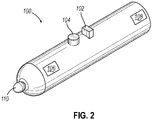
- FIG. 2 shows a perspective view of an exemplary registration probe (100) usable with a surgery navigation system such as the IGS navigation system (10), that may be implemented having one or more features that aid in interactions with the IGS navigation system (10).
- a registration probe (100) may be used with some IGS techniques in order to register the location of various anatomical features of the patient (e.g., the location and orientation of anatomical landmarks on the patient's face) to the IGS navigation system (10) so that it can be correlated with the position of one or more tracked instruments. Examples of various forms that registration probe (100) may take, and registration functionalities that may be provided by registration probe (100), are described in U.S. Pat. No.
- the IGS navigation system (10) provides a tracked space (300) (e.g., an area in which the magnetic field sensors or other sensors can detect the positions and movements of surgical instruments having corresponding sensor elements, as shown in FIG. 3 and discussed in more detail below) in which the position of compatible devices can be tracked.
- This tracked space (300) is a three-dimensional space of varying sizes and shapes and may include at least the space in which the surgical procedure is performed (e.g., for a surgical procedure in or near paranasal sinuses, in a patient's head); but may also include additional portions of space beyond the particular surgical site (e.g., a space extending several feet in each direction from the patient's head).
- the registration probe (100) may be used to locate and register a surgical site, such as the patient's face, with the IGS navigation system (10) so that its position within the tracked space (300) may be determined.
- IGS navigation system (10) may accurately correlate the location of anatomical structures in the patient's head (H) with anatomical structures represented by preoperatively obtained images (e.g., CT scans) and/or digital models, etc. of the patient's head (H) as already stored in IGS navigation system (10).
- the registration probe (100) includes a position sensor that is compatible with the IGS navigation system (10) and allows the registration probe (100) to be located within the tracked space (300); and also includes additional user inputs such as a first button (102), a second button (104), and a wireless transceiver (108).
- a patient may be registered by placing a tip (110) of the registration probe against a plurality of points across the patient's face and registering each point (e.g., manually by pressing a button such as the first button (102), or automatically where the tip (110) is configured to detect contact with the patient's face of a sufficient force to cause automatic registration).
- a position sensor e.g., as could be included in the tip (110) provides that location, within the tracked space (300), to the IGS navigation system (10), which may use such information to correlate the position of any tracked surgical instruments with the patient's position.
- the registration probe (100) may be used to provide one or more features allowing a surgeon to capture information during a procedure, as will be described in more detail below, it should be understood that other surgical instruments that are trackable within the tracked space (300), or that are capable of independently providing signals indicating their position and movements (e.g., by use of accelerometers) and communicating such information to the IGS navigation system (10), may also be advantageously used as described herein. This may include, for example, positionally tracked guidewires, dilation instruments, shavers, endoscopes, cutting tools, and other surgical instruments as will be apparent to those skilled in the art in view of the teachings herein.
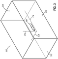
- FIG. 3 shows a diagram showing a surgical instrument such as the registration probe (100) being tracked within the tracked space (300) by a surgery navigation system such as the IGS navigation system (10). While a tracked space may be of varying sizes and shapes, the tracked space (300) is depicted as being a three-dimensional rectangular space in which the registration probe (100) is contained. The registration probe (100) may be tracked in various ways within the tracked space (300) depending upon the capabilities of a particular IGS system and probe (e.g., number and location of position sensors).
- the registration probe (100) may be tracked with three degrees of freedom (e.g., movement along an x, y, and z axis), while in others it may be tracked with six degrees of freedom (e.g., three degrees of freedom, as well as rotations about the x, y, and z axis).
- FIG. 3 shows the registration probe being tracked with three-degrees of freedom, represented by dotted lines, which include tracked movement along an x-axis (308), a y-axis (310), and a z-axis (312).
- Such movements within the tracked space (300) may be interpreted by the IGS navigation system (10) as movements within the three-dimensional space therein; but may also be interpreted as movements within a two-dimensional area.
- the tracked space (300) also includes a first canvas (302), which observes movements of the registration probe (100) along the x-axis (308) and y-axis (310); a second canvas (304), which observes movements along the y-axis (310) and z-axis (312); and a third canvas (306), which observes movements along the x-axis (308) and z-axis (312).
- IGS navigation system (10) or other computer system interfaces may be displayed in two-dimensions
- interpreting movements of a tracked device such as the registration probe (10) in two dimensions may advantageously correspond to such IGS navigation system (10) or other computer system interfaces.
- this may be used for various purposes, such as cursor control of the type that could conventionally be provided by a computer mouse, or text input, such as could be provided by using paths traced using the registration probe (100) (e.g., on a first canvas (302)) as inputs to a handwriting recognition module.
- FIGS. 6A and 6B each show the tracked space (300), with the registration probe's (100) position projected onto the first canvas (302), while FIGS. 7A and 7B show corresponding cursor positions on a display screen (16).
- FIGS. 6A and 6B show the tracked space (300), with the registration probe's (100) position projected onto the first canvas (302)
- FIGS. 7A and 7B show corresponding cursor positions on a display screen (16).
- this is a descriptive term intended to aid in visualizing the movement of the registration probe (100) within the tracked space (300), relative to a specified viewpoint (e.g., the first canvas (302)).
- the IGS navigation system (10) is not required to create corresponding software objects for canvases or projected points, or perform corresponding actions, though in some implementations it may do so.
- the projection may or may not be configured such that the first canvas (or other two-dimensional space used to define the movements of the probe) would conform to any physical object.
- the tracked space (300) may be oriented for purposes of input capture such that the first canvas (302) lays flat against the display screen (16) or against a wall of an operating theater (not pictured). However, this is not required and may not be present in all versions.
- the registration probe (100) is positioned at the approximate midpoint of the first canvas (302), as can be seen by the position (600) projected onto the first canvas (302).
- the position (600) corresponds to the position of a cursor (704) in an interface (700) that may be displayed on the display screen (16) or another device.
- An interface element (702) may be readable text, an image, a clickable button or other control, or another similar feature that may be displayed to a user.
- FIG. 6B the registration probe (100) has been moved downwards and to the right within the tracked space (300), as can be seen by the position (602) projected onto the first canvas (302).
- the position (602) corresponds to the position of the cursor (704), which has moved a direction and distance corresponding to the movement of the registration probe (100) within the tracked space (300).
- the registration probe (100) can be used to control the movements of the cursor (704), in a manner that might otherwise require tools such as optical mice or keyboards that may not be suited to the surgical environment.
- the registration probe (100), or another surgical instrument is already intended for use during a surgical procedure, it may provide such functionality without introducing an additional device or tool to the surgical area (e.g., as a stand-alone non-contact pointing device might) or requiring special implementation considerations (e.g., specially designing a mouse, keyboard, or other conventional input device to make it suitable for sterile procedure use and sterilization).
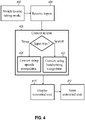
- FIG. 4 depicts an exemplary set of high-level steps for note taking using a registration probe (100).
- a registration probe (100) will be switched (402) into note taking mode. This may be done, for example, by actuating a button (e.g., second button (104)) on the registration probe (100) after registration of the patient's position in three-dimensional space has been completed. In some versions, this may cause a signal to be sent from the registration probe (100) which would cause the processor (12) of the IGS navigation system (10) to display a note taking application on the display screen (16).
- a button e.g., second button (104)
- the IGS navigation system (10) could receive (404) inputs from the registration probe (100). This could be done, for example, by receiving location and orientation information from the registration probe and projecting a line from the tip of the probe to a virtual surface such as the first canvas (302), as previously described in the context of FIGS. 3 , 6A , 6B , 7A and 7B . Alternatively, in some versions, this may be done by receiving speech input, such as could be captured by a microphone (106) included in the registration probe (100).
- Whether input is received (404) in the form of location and orientation information or speech information may vary between versions (e.g., some versions may be configured to capture input in the form of location and orientation information, while other versions may be configured to capture input in the form of speech). However, it is also possible that some versions may be configured to receive input (404) in the form of both speech and location/orientation information.
- first button (102) if a user actuates the first button (102) then input may be captured in the form of speech (e.g., if the user speaks while holding down the first button (102), or if the user speaks after using the first button to turn on speech mode (102) but before using first button (102) to turn off speech mode, etc.), while if the user actuates the second button (104) then input may be captured in the form of position and orientation information.
- Other variations e.g., a variation in which input can be captured in multiple manners that starts in a default input capture mode and cycles through other input capture modes based on button presses
- the above description of various manners for receiving input (404) should be understood as being illustrative only, and should not be treated as limiting.
- the conversion (406) of those inputs into text may take place in a variety of manners.
- the conversion (406) of that input to text may include using the location and orientation information to project a location onto a first canvas (302), buffering locations on the first canvas (302) reflecting changes in location and/or orientation over time, and converting (310) patterns created by the buffered locations into text using handwriting recognition software.
- the input may converted (408) to text using speech recognition software.
- the text could be displayed (410), such in a window displayed by a note taking application, and stored (412), such as in memory comprised by the IGS navigation system (10). Additionally, in some implementations this storage (412) of text may be accompanied by storage of additional information related to the text. For example, in some implementations, converted text may be stored with temporal information (e.g., timestamps) indicating when the underlying input was received (404). This could later be used to correlate specific text with specific parts of the procedure, so that notes could effectively function as annotations in the event a user was reviewing a replay of endoscopic images captured during the procedure.
- temporal information e.g., timestamps
- converted text may be stored along with copies of the original input, so that if there was an error in the conversion process, the original input could be used as a reference for later disambiguation or correction.
- Other variations, such as combinations storing both original input and temporal information, are also possible, and will be immediately apparent to and could be implemented without undue experimentation by, those of ordinary skill in the art in light of this disclosure. Accordingly, the above examples should be understood as being illustrative only, and should not be treated as limiting.
- FIG. 5 depicts a method in which a registration probe (100) is used to write on, paint or otherwise add information to a screen.
- a registration probe (100) would initially be switched (502) into markup mode. This may be done in manners similar to those described above in the context of FIG. 4 , such as actuating a button on the registration probe (100) that would cause a signal to be sent to the IGS navigation system (10) indicating that the user wished to use the registration probe (100) to mark up images on the IGS navigation system's display screen (16).
- the IGS navigation system (10) may treat position and orientation information it receives (504) from the registration probe as input relative to its display screen (16). This may be done, for example, by treating the registration probe (100) as existing in a tracked space (300) in which the first canvas (302) is coincident with the display screen (16) (e.g., by mapping a default coordinate system for the tracked space (300) onto a coordinate system in which the display screen (16) was coincident with the first canvas (302)). This may include steps in which the registration probe would be used to register the display screen (16) in the tracked space in a manner similar to the registration of a patient's body as described above.
- the orientation and location of the registration probe (100) as detected by the IGS navigation system (10) could then be used to project a ray from the tip of the registration probe which would be treated as defining the user's input at the point where the ray intersected the first canvas (302).
- This may be achieved in a variety of manners.
- this ray may be projected at an orientation which is coincident with the orientation of the probe's major axis in the tracked space (300), while in other cases, the tip of the probe in a two-dimensional plana parallel to the first canvas (302) may be projected directly onto the first canvas (302), essentially flattening any three-dimensional motion the probe may experience.
- an IGS navigation system (10) may further require that the user perform some additional action, such as actuating a first button (102) or a second button (104) while moving the registration probe (100) for the location and orientation information to be treated as defining input relative to the display screen (16).
- the user's input could be illustrated (506) on the display screen (16) in the same way if the user had provided input to a drawing program using a tool such as a light pen.
- This could then be stored (508) in a memory of the IGS navigation system (10), such as in connection with whatever image(s) were on the display screen at the time the user's input was received (504), so that the user could later retrieve the images marked up with whatever input he or she had provided.
- This could be used for a variety of purposes, such as surgical pre-planning, or in conjunction with note taking (e.g., where notes and screen markup may be coordinated via timestamps) as described previously.
- a microphone (106) may be used to provide spoken input that would be converted (408) into textual notes via speech recognition
- a microphone (106) comprised by a registration probe (100) may be used for other purposes, such as providing spoken commands for controlling the IGS navigation system (10) during a procedure (e.g., if the registration probe (100) was switched to a voice command mode, such as through actuation of buttons as described previously).
- a IGS navigation system (10) may be configured with software which would automatically capture such spoken commands and incorporate them into a report following a procedure's conclusion.
- FIG. 2 illustrated a potential form factor for a registration probe (100)
- FIGS. 2 and 8 illustrate forms for a registration probe (100) which include a first button (102) and a second button (104) which a user could actuate to control interactions with the IGS navigation system (10)
- the disclosed technology may be implemented using a registration probe which includes more, or fewer, buttons than shown in FIGS. 2 and 8 .
- a registration probe (100) may be implemented to include additional buttons, which buttons may correspond to additional modes of operation that a user could select, or which may correspond to specific actions that a user could perform (e.g., centering a cursor on a window in a display screen (16).
- a registration probe (100) may be implemented with fewer or no buttons, and software on the IGS navigation system (10) could allow users to perform actions or switch between types of actions that could be performed using gesture control or similar input types.
- a registration probe (100) with a touch sensor implemented in its tip (110) may allow a user to mark up a screen display (16) by using touch signals from the registration probe (100) to indicate that movements detected by the IGS navigation system (10) should be treated as providing inputs (e.g., screen markup).
- a registration probe (100) may be used in a variety of different ways different ways during a procedure. This can include using the registration probe (100) in the pre-operative stage to register anatomical landmarks on a patient's head (H) with the IGS navigation system (10), thereby enabling the IGS navigation system (10) to correlate preoperatively obtained images or digital models of the patient's head (H) with the actual location of the patient's head (H) in a tracked space (300).
- This may be much more convenient and efficient for the surgeon, as it allows the surgeon to avoid interacting with a keyboard or mouse.
- the registration probe (100) may be placed on the patient's chest or some other location that is conveniently accessible to the surgeon.
- a method of using an image guided surgery (IGS) navigation system comprising: activating a tracking field generator comprising a set of magnetic field generators operable to produce a magnetic field defining a tracked area comprising a head of a subject; using a probe comprising a position sensor to measure a plurality of magnetic field positions on the head of the subject; generating a registration between the head of the subject and an image of the head of the subject based on the measurement of the plurality of magnetic field positions on the head of the subject; putting the IGS navigation system into an input mode using a control on the probe; and while the IGS navigation system is in the input mode, using the probe to capture an input from a user.
- IGS image guided surgery
- Example 1 The method of Example 1, wherein the method comprises: generating text based on the input from the user; displaying the text on an interface of a note taking application; and storing the text in a memory of the IGS navigation system.
- generating text based on the input from the user comprises: generating an input pattern by performing steps comprising buffering the input from the user; and providing the input pattern to a handwriting recognition program.
- Example 2 wherein the input from the user is spoken input captured by a microphone comprised by the probe; and generating text based on the input from the user comprises providing the spoken input to a speech recognition program.
- storing the text in the memory of the IGS navigation system comprises storing the text with a timestamp corresponding to a time for the input from the user.
- the input mode is a note taking mode; and the method comprises: receiving a signal from the probe indicating actuation of a button comprised by the probe; and automatically putting the IGS navigation system into the note taking mode and activating the note taking application based on receiving the signal from the probe.
- Example 1 wherein: using the probe to capture the input from the user comprises defining a pattern based on movement of an intersection of a ray extending from a tip of the probe to a plane in the tracked area defined by the magnetic field; and the method comprises displaying the pattern on a display of the IGS navigation system.
- Example 7 wherein the method comprises: using the probe to measure a plurality of magnetic field positions on the display of the IGS navigation system; and generating a registration between the display of the IGS navigation system and the plane in the tracked area based on the measurement of the plurality of magnetic field positions on the display of the IGS navigation system.
- displaying the pattern on the display of the IGS navigation system comprises displaying the pattern overlaid on an image of an interior of the subject during pre-operative planning.
- displaying the pattern on the display of the IGS navigation system comprises displaying the pattern overlaid on a real time image of an interior of the subject during a procedure.
- the input captured using the probe comprises a voice command; and the method comprises automatically: converting the voice command to text; and incorporating the text into a report of a procedure performed on the subject.
- the probe comprises a first button, a second button, and a microphone
- the IGS navigation system is configured to: when the first button is depressed, treat movements of the probe within the tracked area as the input; and when the second button is depressed, treat sound captured by the microphone as the input.
- An image guided surgery (IGS) navigation system comprising: a probe comprising a position sensor; a tracking field generator operable to provide a tracked area, wherein the tracked area is a three dimensional space; a processor configured to: determine a position of the probe within the tracked area based upon a set of tracking data, wherein the set of tracking data is based on signals from the position sensor received by the processor as a result of an interaction of the probe with the tracked area; generate a registration between a head of a subject and an image of the head of the subject based on measurements from the probe of a plurality of magnetic field positions of the head of the subject; switching to an input mode based on a control signal received from the probe; and while in the input mode, receiving an input signal from the probe.
- IGS image guided surgery
- the IGS navigation system of Example 16 wherein the processor of the IGS navigation system is configured to generate text based on the input signal from the probe using a program selected from a group consisting of: a handwriting recognition program; and a speech recognition program.
- An IGS navigation system comprising: a probe comprising a position sensor, a microphone, a first button and a second button; a tracking field generator operable to provide a tracked area, wherein the tracked area is a three dimensional space; a processor configured to: determine a position of the probe within the tracked area based upon a set of tracking data, wherein the set of tracking data is based on signals from the position sensor received by the processor as a result of an interaction of the probe with the tracked area; generate a registration between a head of a subject an image of the head of the subject based on measurements from the probe of a plurality of magnetic field positions of the head of the subject; receive a first signal indicating that the first button is depressed, and a second signal indicating that the second button is depressed; when the registration has been generated and the first button is depressed, treat movements of the probe within the tracked area of the magnetic tracking system as input from a user of the probe; and when the registration has been generated and the second button is depressed, treat sound captured by the microphone as
- any of the examples described herein may include various other features in addition to or in lieu of those described above.
- any of the examples described herein may also include one or more of the various features disclosed in any of the various references that are incorporated by reference herein.
Landscapes
- Engineering & Computer Science (AREA)
- Health & Medical Sciences (AREA)
- Surgery (AREA)
- Life Sciences & Earth Sciences (AREA)
- Theoretical Computer Science (AREA)
- General Engineering & Computer Science (AREA)
- Public Health (AREA)
- Heart & Thoracic Surgery (AREA)
- Medical Informatics (AREA)
- Molecular Biology (AREA)
- Animal Behavior & Ethology (AREA)
- General Health & Medical Sciences (AREA)
- Robotics (AREA)
- Biomedical Technology (AREA)
- Veterinary Medicine (AREA)
- Nuclear Medicine, Radiotherapy & Molecular Imaging (AREA)
- Human Computer Interaction (AREA)
- Physics & Mathematics (AREA)
- General Physics & Mathematics (AREA)
- Computer Hardware Design (AREA)
- Ultra Sonic Daignosis Equipment (AREA)
- Magnetic Resonance Imaging Apparatus (AREA)
- Position Input By Displaying (AREA)
- User Interface Of Digital Computer (AREA)
Applications Claiming Priority (1)
| Application Number | Priority Date | Filing Date | Title |
|---|---|---|---|
| US17/325,256 US12611258B2 (en) | 2021-05-20 | 2021-05-20 | Registration probe for enhanced information capture |
Publications (3)
| Publication Number | Publication Date |
|---|---|
| EP4091568A2 true EP4091568A2 (de) | 2022-11-23 |
| EP4091568A3 EP4091568A3 (de) | 2023-05-17 |
| EP4091568B1 EP4091568B1 (de) | 2026-03-11 |
Family
ID=81749290
Family Applications (1)
| Application Number | Title | Priority Date | Filing Date |
|---|---|---|---|
| EP22174259.6A Active EP4091568B1 (de) | 2021-05-20 | 2022-05-19 | Registriersonde zur verbesserten erfassung von informationen |
Country Status (5)
| Country | Link |
|---|---|
| US (1) | US12611258B2 (de) |
| EP (1) | EP4091568B1 (de) |
| JP (1) | JP2022179431A (de) |
| CN (1) | CN115363756A (de) |
| IL (1) | IL293102A (de) |
Citations (6)
| Publication number | Priority date | Publication date | Assignee | Title |
|---|---|---|---|---|
| US7720521B2 (en) | 2004-04-21 | 2010-05-18 | Acclarent, Inc. | Methods and devices for performing procedures within the ear, nose, throat and paranasal sinuses |
| US20140364725A1 (en) | 2004-04-21 | 2014-12-11 | Acclarent, Inc. | Systems and methods for performing image guided procedures within the ear, nose, throat and paranasal sinuses |
| US10463242B2 (en) | 2014-07-09 | 2019-11-05 | Acclarent, Inc. | Guidewire navigation for sinuplasty |
| US10561370B2 (en) | 2017-04-26 | 2020-02-18 | Accalrent, Inc. | Apparatus to secure field generating device to chair |
| US10779891B2 (en) | 2015-10-30 | 2020-09-22 | Acclarent, Inc. | System and method for navigation of surgical instruments |
| US10786311B2 (en) | 2017-12-22 | 2020-09-29 | Acclarent, Inc. | Apparatus and method for registering facial landmarks for surgical navigation system |
Family Cites Families (24)
| Publication number | Priority date | Publication date | Assignee | Title |
|---|---|---|---|---|
| US7747311B2 (en) * | 2002-03-06 | 2010-06-29 | Mako Surgical Corp. | System and method for interactive haptic positioning of a medical device |
| US7225131B1 (en) * | 2002-06-14 | 2007-05-29 | At&T Corp. | System and method for accessing and annotating electronic medical records using multi-modal interface |
| US8403828B2 (en) * | 2003-07-21 | 2013-03-26 | Vanderbilt University | Ophthalmic orbital surgery apparatus and method and image-guide navigation system |
| US20050113812A1 (en) * | 2003-09-16 | 2005-05-26 | Viswanathan Raju R. | User interface for remote control of medical devices |
| TWI301590B (en) | 2005-12-30 | 2008-10-01 | Ibm | Handwriting input method, apparatus, system and computer recording medium with a program recorded thereon of capturing video data of real-time handwriting strokes for recognition |
| US20070238981A1 (en) * | 2006-03-13 | 2007-10-11 | Bracco Imaging Spa | Methods and apparatuses for recording and reviewing surgical navigation processes |
| US8447611B2 (en) * | 2006-09-05 | 2013-05-21 | Fortemedia, Inc. | Pen-type voice computer and method thereof |
| US20080119712A1 (en) * | 2006-11-20 | 2008-05-22 | General Electric Company | Systems and Methods for Automated Image Registration |
| US7671887B2 (en) * | 2006-11-20 | 2010-03-02 | General Electric Company | System and method of navigating a medical instrument |
| US10806519B2 (en) * | 2007-06-22 | 2020-10-20 | Orthosoft Ulc | Computer-assisted surgery system with user interface tool used as mouse in sterile surgery environment |
| US20090080737A1 (en) * | 2007-09-25 | 2009-03-26 | General Electric Company | System and Method for Use of Fluoroscope and Computed Tomography Registration for Sinuplasty Navigation |
| US9304608B2 (en) * | 2011-12-20 | 2016-04-05 | Htc Corporation | Stylus device |
| US9250721B2 (en) * | 2012-12-17 | 2016-02-02 | Disney Enterprises, Inc. | Wireless stylus device with interchangeable tips and eraser |
| US10328280B2 (en) * | 2013-02-08 | 2019-06-25 | Covidien Lp | System and method for lung denervation |
| US9717442B2 (en) * | 2013-03-15 | 2017-08-01 | Medtronic Navigation, Inc. | Method and system for navigating an instrument |
| KR20160023163A (ko) | 2014-08-21 | 2016-03-03 | 삼성전자주식회사 | 전자 장치 및 전자 펜에 의한 전자 장치의 동작 방법 |
| US10409955B2 (en) | 2014-10-21 | 2019-09-10 | uBiome, Inc. | Method and system for microbiome-derived diagnostics and therapeutics for locomotor system conditions |
| US10722306B2 (en) * | 2015-11-17 | 2020-07-28 | Biosense Webster (Israel) Ltd. | System for tracking guidewire with ray tracing capability |
| EP3609424B1 (de) | 2017-04-14 | 2026-01-14 | Stryker Corporation | Chirurgische systeme zur ermöglichung der interoperativen ad-hoc-planung von chirurgischen eingriffen |
| US10813657B2 (en) * | 2017-10-11 | 2020-10-27 | Biosense Webster (Israel) Ltd. | Debrider warning system |
| US10444868B2 (en) | 2017-11-20 | 2019-10-15 | Cheng Uei Precision Industry Co., Ltd. | Multifunctional stylus with a voice control function and voice control method applied therein |
| US11481909B2 (en) * | 2018-12-06 | 2022-10-25 | Biosense Webster (Israel) Ltd. | Method and apparatus for performing facial registration |
| US11744646B2 (en) * | 2018-12-12 | 2023-09-05 | Acclarent, Inc. | Registration probe for image guided surgery system |
| WO2020210782A1 (en) | 2019-04-11 | 2020-10-15 | Think Surgical, Inc. | System and method to check cut plane accuracy after bone removal |
-
2021
- 2021-05-20 US US17/325,256 patent/US12611258B2/en active Active
-
2022
- 2022-05-18 IL IL293102A patent/IL293102A/en unknown
- 2022-05-19 EP EP22174259.6A patent/EP4091568B1/de active Active
- 2022-05-19 JP JP2022082156A patent/JP2022179431A/ja active Pending
- 2022-05-20 CN CN202210549364.XA patent/CN115363756A/zh active Pending
Patent Citations (6)
| Publication number | Priority date | Publication date | Assignee | Title |
|---|---|---|---|---|
| US7720521B2 (en) | 2004-04-21 | 2010-05-18 | Acclarent, Inc. | Methods and devices for performing procedures within the ear, nose, throat and paranasal sinuses |
| US20140364725A1 (en) | 2004-04-21 | 2014-12-11 | Acclarent, Inc. | Systems and methods for performing image guided procedures within the ear, nose, throat and paranasal sinuses |
| US10463242B2 (en) | 2014-07-09 | 2019-11-05 | Acclarent, Inc. | Guidewire navigation for sinuplasty |
| US10779891B2 (en) | 2015-10-30 | 2020-09-22 | Acclarent, Inc. | System and method for navigation of surgical instruments |
| US10561370B2 (en) | 2017-04-26 | 2020-02-18 | Accalrent, Inc. | Apparatus to secure field generating device to chair |
| US10786311B2 (en) | 2017-12-22 | 2020-09-29 | Acclarent, Inc. | Apparatus and method for registering facial landmarks for surgical navigation system |
Also Published As
| Publication number | Publication date |
|---|---|
| US20220370143A1 (en) | 2022-11-24 |
| CN115363756A (zh) | 2022-11-22 |
| JP2022179431A (ja) | 2022-12-02 |
| EP4091568A3 (de) | 2023-05-17 |
| IL293102A (en) | 2022-12-01 |
| EP4091568B1 (de) | 2026-03-11 |
| US12611258B2 (en) | 2026-04-28 |
Similar Documents
| Publication | Publication Date | Title |
|---|---|---|
| JP7816722B2 (ja) | センサベースのナビゲーションと内視鏡検査との組み合わせを用いた外科用システム | |
| US11259870B2 (en) | Interactive user interfaces for minimally invasive telesurgical systems | |
| CN110876643B (zh) | 医疗手术导航系统及方法 | |
| US12376914B2 (en) | Registration probe for image guided surgery system | |
| US8398541B2 (en) | Interactive user interfaces for robotic minimally invasive surgical systems | |
| US20080123910A1 (en) | Method and system for providing accuracy evaluation of image guided surgery | |
| US10575755B2 (en) | Computer-implemented technique for calculating a position of a surgical device | |
| US20070073137A1 (en) | Virtual mouse for use in surgical navigation | |
| US20070073133A1 (en) | Virtual mouse for use in surgical navigation | |
| US20150287236A1 (en) | Imaging system, operating device with the imaging system and method for imaging | |
| JP6706576B2 (ja) | 最小侵襲性のインターベンションのための形状センスされるロボット超音波 | |
| EP4316400A2 (de) | Vorrichtung und verfahren zur registrierung von gesichtsmarkierungen für ein chirurgisches navigationssystem | |
| US12079440B2 (en) | Method for real time update of fly-through camera placement | |
| CN117582288A (zh) | 配置用于执行插入路径近似的空间感知医疗设备 | |
| AU2018202682A1 (en) | Endoscopic view of invasive procedures in narrow passages | |
| US12507864B2 (en) | Interactive augmented reality system for laparoscopic and video assisted surgeries | |
| Abdurahiman et al. | Human-computer interfacing for control of angulated scopes in robotic scope assistant systems | |
| EP4091568A2 (de) | Registriersonde zur verbesserten erfassung von informationen | |
| JP4717683B2 (ja) | 医用画像表示装置 | |
| US20240164844A1 (en) | Bone landmarks extraction by bone surface palpation using ball tip stylus for computer assisted surgery navigation | |
| JP2002017751A (ja) | 手術ナビゲーション装置 | |
| WO2025150057A1 (en) | "system for image-guided surgery" | |
| KR20250016315A (ko) | 이미징 자세 추천 생성 | |
| WO2025229542A1 (en) | Target localization for percutaneous access | |
| JP4703161B2 (ja) | 核磁気共鳴撮像装置 |
Legal Events
| Date | Code | Title | Description |
|---|---|---|---|
| PUAI | Public reference made under article 153(3) epc to a published international application that has entered the european phase |
Free format text: ORIGINAL CODE: 0009012 |
|
| STAA | Information on the status of an ep patent application or granted ep patent |
Free format text: STATUS: THE APPLICATION HAS BEEN PUBLISHED |
|
| AK | Designated contracting states |
Kind code of ref document: A2 Designated state(s): AL AT BE BG CH CY CZ DE DK EE ES FI FR GB GR HR HU IE IS IT LI LT LU LV MC MK MT NL NO PL PT RO RS SE SI SK SM TR |
|
| RIC1 | Information provided on ipc code assigned before grant |
Ipc: A61B 17/00 19680901ALN20230109BHEP Ipc: G10L 15/26 20000101ALI20230109BHEP Ipc: G06F 3/04883 20220101ALI20230109BHEP Ipc: A61B 34/20 20160101AFI20230109BHEP |
|
| PUAL | Search report despatched |
Free format text: ORIGINAL CODE: 0009013 |
|
| AK | Designated contracting states |
Kind code of ref document: A3 Designated state(s): AL AT BE BG CH CY CZ DE DK EE ES FI FR GB GR HR HU IE IS IT LI LT LU LV MC MK MT NL NO PL PT RO RS SE SI SK SM TR |
|
| RIC1 | Information provided on ipc code assigned before grant |
Ipc: A61B 17/00 20060101ALN20230411BHEP Ipc: G10L 15/26 20060101ALI20230411BHEP Ipc: G06F 3/04883 20220101ALI20230411BHEP Ipc: A61B 34/20 20160101AFI20230411BHEP |
|
| STAA | Information on the status of an ep patent application or granted ep patent |
Free format text: STATUS: REQUEST FOR EXAMINATION WAS MADE |
|
| 17P | Request for examination filed |
Effective date: 20231116 |
|
| RBV | Designated contracting states (corrected) |
Designated state(s): AL AT BE BG CH CY CZ DE DK EE ES FI FR GB GR HR HU IE IS IT LI LT LU LV MC MK MT NL NO PL PT RO RS SE SI SK SM TR |
|
| GRAP | Despatch of communication of intention to grant a patent |
Free format text: ORIGINAL CODE: EPIDOSNIGR1 |
|
| STAA | Information on the status of an ep patent application or granted ep patent |
Free format text: STATUS: GRANT OF PATENT IS INTENDED |
|
| RIC1 | Information provided on ipc code assigned before grant |
Ipc: A61B 34/20 20160101AFI20250908BHEP Ipc: G06F 3/04883 20220101ALI20250908BHEP Ipc: G06F 1/16 20060101ALI20250908BHEP Ipc: G06F 3/0481 20220101ALI20250908BHEP Ipc: G06F 3/04842 20220101ALI20250908BHEP Ipc: A61B 17/00 20060101ALN20250908BHEP |
|
| INTG | Intention to grant announced |
Effective date: 20250917 |
|
| GRAS | Grant fee paid |
Free format text: ORIGINAL CODE: EPIDOSNIGR3 |
|
| GRAJ | Information related to disapproval of communication of intention to grant by the applicant or resumption of examination proceedings by the epo deleted |
Free format text: ORIGINAL CODE: EPIDOSDIGR1 |
|
| GRAL | Information related to payment of fee for publishing/printing deleted |
Free format text: ORIGINAL CODE: EPIDOSDIGR3 |
|
| STAA | Information on the status of an ep patent application or granted ep patent |
Free format text: STATUS: REQUEST FOR EXAMINATION WAS MADE |
|
| GRAP | Despatch of communication of intention to grant a patent |
Free format text: ORIGINAL CODE: EPIDOSNIGR1 |
|
| STAA | Information on the status of an ep patent application or granted ep patent |
Free format text: STATUS: GRANT OF PATENT IS INTENDED |
|
| GRAA | (expected) grant |
Free format text: ORIGINAL CODE: 0009210 |
|
| STAA | Information on the status of an ep patent application or granted ep patent |
Free format text: STATUS: THE PATENT HAS BEEN GRANTED |
|
| INTC | Intention to grant announced (deleted) | ||
| RIC1 | Information provided on ipc code assigned before grant |
Ipc: A61B 34/20 20160101AFI20260121BHEP Ipc: G06F 3/04883 20220101ALI20260121BHEP Ipc: G06F 1/16 20060101ALI20260121BHEP Ipc: G06F 3/0481 20220101ALI20260121BHEP Ipc: G06F 3/04842 20220101ALI20260121BHEP Ipc: A61B 17/00 20060101ALN20260121BHEP |
|
| INTG | Intention to grant announced |
Effective date: 20260129 |
|
| AK | Designated contracting states |
Kind code of ref document: B1 Designated state(s): AL AT BE BG CH CY CZ DE DK EE ES FI FR GB GR HR HU IE IS IT LI LT LU LV MC MK MT NL NO PL PT RO RS SE SI SK SM TR |
|
| REG | Reference to a national code |
Ref country code: CH Ref legal event code: F10 Free format text: ST27 STATUS EVENT CODE: U-0-0-F10-F00 (AS PROVIDED BY THE NATIONAL OFFICE) Effective date: 20260311 Ref country code: GB Ref legal event code: FG4D |
|
| REG | Reference to a national code |
Ref country code: DE Ref legal event code: R096 Ref document number: 602022031977 Country of ref document: DE |
|
| REG | Reference to a national code |
Ref country code: IE Ref legal event code: FG4D |