EP4091802A1 - Dry spot tool for creating a dry spot in a composite part - Google Patents
Dry spot tool for creating a dry spot in a composite part Download PDFInfo
- Publication number
- EP4091802A1 EP4091802A1 EP21174154.1A EP21174154A EP4091802A1 EP 4091802 A1 EP4091802 A1 EP 4091802A1 EP 21174154 A EP21174154 A EP 21174154A EP 4091802 A1 EP4091802 A1 EP 4091802A1
- Authority
- EP
- European Patent Office
- Prior art keywords
- dry spot
- tool
- dry
- tool body
- outlets
- Prior art date
- Legal status (The legal status is an assumption and is not a legal conclusion. Google has not performed a legal analysis and makes no representation as to the accuracy of the status listed.)
- Granted
Links
Images


Classifications
-
- B—PERFORMING OPERATIONS; TRANSPORTING
- B29—WORKING OF PLASTICS; WORKING OF SUBSTANCES IN A PLASTIC STATE IN GENERAL
- B29C—SHAPING OR JOINING OF PLASTICS; SHAPING OF MATERIAL IN A PLASTIC STATE, NOT OTHERWISE PROVIDED FOR; AFTER-TREATMENT OF THE SHAPED PRODUCTS, e.g. REPAIRING
- B29C70/00—Shaping composites, i.e. plastics material comprising reinforcements, fillers or preformed parts, e.g. inserts
- B29C70/04—Shaping composites, i.e. plastics material comprising reinforcements, fillers or preformed parts, e.g. inserts comprising reinforcements only, e.g. self-reinforcing plastics
- B29C70/28—Shaping operations therefor
- B29C70/40—Shaping or impregnating by compression not applied
- B29C70/42—Shaping or impregnating by compression not applied for producing articles of definite length, i.e. discrete articles
- B29C70/44—Shaping or impregnating by compression not applied for producing articles of definite length, i.e. discrete articles using isostatic pressure, e.g. pressure difference-moulding, vacuum bag-moulding, autoclave-moulding or expanding rubber-moulding
- B29C70/443—Shaping or impregnating by compression not applied for producing articles of definite length, i.e. discrete articles using isostatic pressure, e.g. pressure difference-moulding, vacuum bag-moulding, autoclave-moulding or expanding rubber-moulding and impregnating by vacuum or injection
-
- B—PERFORMING OPERATIONS; TRANSPORTING
- B29—WORKING OF PLASTICS; WORKING OF SUBSTANCES IN A PLASTIC STATE IN GENERAL
- B29C—SHAPING OR JOINING OF PLASTICS; SHAPING OF MATERIAL IN A PLASTIC STATE, NOT OTHERWISE PROVIDED FOR; AFTER-TREATMENT OF THE SHAPED PRODUCTS, e.g. REPAIRING
- B29C70/00—Shaping composites, i.e. plastics material comprising reinforcements, fillers or preformed parts, e.g. inserts
- B29C70/04—Shaping composites, i.e. plastics material comprising reinforcements, fillers or preformed parts, e.g. inserts comprising reinforcements only, e.g. self-reinforcing plastics
- B29C70/28—Shaping operations therefor
- B29C70/54—Component parts, details or accessories; Auxiliary operations, e.g. feeding or storage of prepregs or SMC after impregnation or during ageing
- B29C70/545—Perforating, cutting or machining during or after moulding
-
- B—PERFORMING OPERATIONS; TRANSPORTING
- B29—WORKING OF PLASTICS; WORKING OF SUBSTANCES IN A PLASTIC STATE IN GENERAL
- B29C—SHAPING OR JOINING OF PLASTICS; SHAPING OF MATERIAL IN A PLASTIC STATE, NOT OTHERWISE PROVIDED FOR; AFTER-TREATMENT OF THE SHAPED PRODUCTS, e.g. REPAIRING
- B29C70/00—Shaping composites, i.e. plastics material comprising reinforcements, fillers or preformed parts, e.g. inserts
- B29C70/04—Shaping composites, i.e. plastics material comprising reinforcements, fillers or preformed parts, e.g. inserts comprising reinforcements only, e.g. self-reinforcing plastics
- B29C70/28—Shaping operations therefor
- B29C70/54—Component parts, details or accessories; Auxiliary operations, e.g. feeding or storage of prepregs or SMC after impregnation or during ageing
- B29C70/546—Measures for feeding or distributing the matrix material in the reinforcing structure
- B29C70/548—Measures for feeding or distributing the matrix material in the reinforcing structure using distribution constructions, e.g. channels incorporated in or associated with the mould
-
- B—PERFORMING OPERATIONS; TRANSPORTING
- B29—WORKING OF PLASTICS; WORKING OF SUBSTANCES IN A PLASTIC STATE IN GENERAL
- B29C—SHAPING OR JOINING OF PLASTICS; SHAPING OF MATERIAL IN A PLASTIC STATE, NOT OTHERWISE PROVIDED FOR; AFTER-TREATMENT OF THE SHAPED PRODUCTS, e.g. REPAIRING
- B29C2793/00—Shaping techniques involving a cutting or machining operation
- B29C2793/0009—Cutting out
- B29C2793/0018—Cutting out for making a hole
-
- B—PERFORMING OPERATIONS; TRANSPORTING
- B29—WORKING OF PLASTICS; WORKING OF SUBSTANCES IN A PLASTIC STATE IN GENERAL
- B29C—SHAPING OR JOINING OF PLASTICS; SHAPING OF MATERIAL IN A PLASTIC STATE, NOT OTHERWISE PROVIDED FOR; AFTER-TREATMENT OF THE SHAPED PRODUCTS, e.g. REPAIRING
- B29C2793/00—Shaping techniques involving a cutting or machining operation
- B29C2793/009—Shaping techniques involving a cutting or machining operation after shaping
-
- B—PERFORMING OPERATIONS; TRANSPORTING
- B29—WORKING OF PLASTICS; WORKING OF SUBSTANCES IN A PLASTIC STATE IN GENERAL
- B29L—INDEXING SCHEME ASSOCIATED WITH SUBCLASS B29C, RELATING TO PARTICULAR ARTICLES
- B29L2031/00—Other particular articles
- B29L2031/08—Blades for rotors, stators, fans, turbines or the like, e.g. screw propellers
- B29L2031/082—Blades, e.g. for helicopters
- B29L2031/085—Wind turbine blades
-
- Y—GENERAL TAGGING OF NEW TECHNOLOGICAL DEVELOPMENTS; GENERAL TAGGING OF CROSS-SECTIONAL TECHNOLOGIES SPANNING OVER SEVERAL SECTIONS OF THE IPC; TECHNICAL SUBJECTS COVERED BY FORMER USPC CROSS-REFERENCE ART COLLECTIONS [XRACs] AND DIGESTS
- Y02—TECHNOLOGIES OR APPLICATIONS FOR MITIGATION OR ADAPTATION AGAINST CLIMATE CHANGE
- Y02P—CLIMATE CHANGE MITIGATION TECHNOLOGIES IN THE PRODUCTION OR PROCESSING OF GOODS
- Y02P70/00—Climate change mitigation technologies in the production process for final industrial or consumer products
- Y02P70/50—Manufacturing or production processes characterised by the final manufactured product
Definitions
- the invention relates to a dry spot tool for creating a dry spot in a composite material of a wind turbine during vacuum assisted resin transfer molding, a dry spot arrangement comprising the dry spot tool and a vacuum system and a method for manufacturing a composite part with a dry spot by means of vacuum assisted resin transfer molding using the dry spot arrangement.
- an intended and controlled dry spot formation in particular with respect to size and location of the dry spot, may provide advantageous composite parts, in which the dry spots may fulfil certain functions of the unit, for example a wind turbine, in which the manufactured composite part is later used.
- a dry spot tool for creating a dry spot in a composite part of a wind turbine during vacuum assisted resin transfer molding.
- the dry spot tool has a tool body.
- the tool body comprises a perimeter.
- the tool body extends along the perimeter and has an opening in the center of the perimeter for creating the dry spot in an area of the opening.
- the tool body further has a top side and a bottom side.
- the top side is opposite of the bottom side and the bottom side has at least one bottom surface.
- the tool body also has outlets.
- the outlets are fluidically connected to inlets of the dry spot tool.
- the inlets are configured for connecting hoses of a vacuum system thereto.
- the tool body comprises a flow passage.
- the flow passage fluidically connects the outlets with one another.
- the flow passage extends at least for a partial length thereof along the perimeter of the tool body.
- the flow passage extends at least for a partial length thereof in width from the outlets to the bottom side.
- the usage of the dry spot tool allows the creation of dry spots in the composite part during the manufacturing process of vacuum assisted resin transfer molding. This may be done by placing the dry spot tool on top of a reinforcement material, in particular fiber material and having multiple layers, which may be placed on top of a mold or draped onto the mold. A seal cover may afterwards be placed on both, the reinforcement material and the dry spot tool. The dry spot tool may then be attached to the vacuum system. Then, the space between the mold and the seal cover may be supplied with liquid matrix material, in particular resin, by means of applying a vacuum for infusing the reinforcement material with the liquid matrix material as generally known in the state of the art.
- vacuum assisted resin transfer molding vacuum may be supplied to the dry spot tool by means of the vacuum system.
- This vacuum provides for firm attachment of the dry spot tool to the reinforcement material.
- a vacuum is created inside of the flow passage connected via the outlets to the inlets connected to the vacuum system.
- the bottom side of the dry spot tool with the vacuum inside the flow passage accordingly may press against the mold having the reinforcement material in between and attach with its at least one bottom surface to the reinforcement material and mold.
- the tool body thereby prevents the liquid matrix material from flowing from outside of the dry spot tool into the inside of the dry spot tool defined by its opening during the vacuum assisted infusion process.
- the area outside of the dry spot tool is soaked or wetted with the liquid matrix material and may cure.
- the area inside of the opening of the dry spot tool has remained dry during the manufacturing process, thereby resulting in the dry spot.
- the use of the dry spot tool will be described later in more detail with reference to the manufacturing method making use of the dry spot tool.
- the dry spot tool thereby allows for a particular simple and inexpensive method of creating a dry spot in a controlled manner.
- the dry spot tool may essentially create the dry spot at any location of the composite material and in any size.
- the dry spot tool may essentially be placed on any area of the matrix reinforcement material or mold.
- the opening or overall dry spot tool may be dimensioned according to the desired dry spot size.
- the dry spot tool is not limited to flat or planar geometries of the mold or composite part to be manufactured but may be adjusted in the shape of its tool body to correspond to the geometry of the mold or composite part at the location at which the dry spot is to be created.
- the tool body in particular its bottom side, may be curved or have one or multiple edges.
- the composite part to be manufactured is a rotor blade of a wind turbine and the dry spot is to be created on the leading edge of the rotor blade
- the tool body may be designed with its geometry corresponding to the geometry of the leading edge at the location in which the dry spot is to be created in the rotor blade made from the composite material.
- the tool body or the entire dry spot tool may be designed monolithically or, in other words, from a single piece of material. It is preferable that the dry spot tool is made from plastic, which is particularly inexpensive. Preferably, the tool body or the entire dry spot tool may be manufactured by an additive manufacturing process, which allows to manufacture the dry spot tool with great freedom with respect to its geometry and inexpensively provide different dry spot tools for different places of dry spots to be created on geometrically complex composite parts.
- the at least one bottom surface on the bottom side of the tool body may be a substantially smooth surface. Thereby, it may be prevented that gaps occur between the reinforcement material and the tool body, which might allow the liquid matrix material to enter the inside of the dry spot tool, eventually resulting in an undesired infusion of the area inside of the dry spot tool, where the dry spot shall be created.
- a particular preferable application of the dry spot tool is in manufacturing processes of composite parts of wind turbines, such as rotor blades, for example, as these are comparatively large, may have complex geometry and are therefore difficult to manufacture.
- the dry spot in the composite parts of wind turbines may fulfill different functions associated with the wind turbine, as will be explained in more detail later on.
- the dry spot tool may be used for other composite parts than from wind turbines as well and the dry spot tool and its associated method for manufacturing a composite part with a dry spot are not limited to composite parts of wind turbines.
- the composite part may alternatively be of any other structure, such as, for example, a car, an airplane, or similar.
- the flow passage may substantially extend along the entire perimeter of the tool body.
- substantially herein means that the flow passage extends along the entire or nearly the entire perimeter, in particular along at least 95 % of the perimeter, of the tool body.
- the vacuum generated inside of the flow passage may completely or nearly completely attach the tool body to the reinforcement material on which it may be placed. Thereby, it may be prevented that a gap between the tool body and reinforcement material allows liquid matrix material to flow from outside of the dry spot tool into the inside or opening thereof, which would result in undesired infusion of the area inside of the dry spot tool.
- the flow passage may extend substantially along its entire length in width from the outlets to the bottom side. Substantially herein means that the flow passage extends along its entire length or nearly its entire length in width from the outlets to the bottom side, in particular along at least 95 % of its length.
- the vacuum generated inside of the flow passage may completely or nearly completely attach the tool body to the reinforcement material on which it may be placed. Thereby, it may be prevented that a gap between the tool body and reinforcement material allows liquid matrix material to flow from outside of the dry spot tool into the inside or opening thereof, which would result in undesired infusion of the area inside of the dry spot tool.
- the flow passage may extend from an inside of the tool body, in which the outlets are located, to the bottom side.
- the flow passage may be designed as a cavity or groove inside of the tool body.
- the cavity or groove may be open towards or at the bottom side such that the flow passage extends in width to the bottom side.
- the width or, in other words, diameter of the dry spot tool is understood as the extension of the flow passage perpendicular to its length or, in other words, longitudinal extension.
- the bottom side may have two bottom surfaces separated from one another by means of the flow passage located in between the two bottom surfaces.
- the two bottom surfaces may be part of two separate walls of the tool body, in between which the flow passage, in particular cavity or groove, extends.
- the two bottom surfaces may share one common level or plane.
- the flow passage with its open side is being (nearly) closed by sucking onto the mold or reinforcement material functioning as a closure, whereas the two bottom surfaces attach to the mold or reinforcement material effectively shutting off the flow passage from the outside of the dry spot tool and the inside or opening of the dry spot tool.
- the two bottom surfaces very effectively prevent the liquid matrix material flowing outside of the dry spot tool from flowing into the opening of the dry spot tool, because there are two walls which would need to be passed by the liquid matrix material to get into the area of the dry spot to be created.
- Each one of the inlets may be respectively fluidically connected to one of the outlets via a respective one of multiple flow channels.
- the flow channels may be at least partially provided in the tool body.
- the inlets may in particular be provided on the top side of the tool body.
- the dry spot tool may comprise nozzles extending away from the top side of the tool body. Each one of the nozzles may have one of the inlets of the dry spot tool.
- the number of nozzles may correspond to the number of outlets.
- the number of nozzles may be two, three, four or more, for example.
- the nozzles may be spatially distributed with equal distance from one another on the dry spot tool. Also, or alternatively, the inlets and/or outlets may be spatially distributed with equal distance from one another on the dry spot tool.
- the individual flow channels may, in addition to being formed inside of the tool body, also be formed inside of the nozzles, thereby extending along the nozzles and the tool body.
- the nozzles may be made separate from the tool body and attached to the tool body.
- the nozzles may be made from a different material than the tool body.
- the nozzles may be made from a flexible material, allowing flexibility for attaching the hoses of the vacuum system thereto.
- rubber may be chosen as a flexible material.
- the nozzles may be monolithically or, in other words, integrally formed with the tool body.
- the tool body may have a substantially circular, square or triangular shape, for example.
- the circular shape of the tool body preferably allows for a good distribution of the negative pressure generated by the vacuum system.
- the dry spot may be provided as a circular dry spot. This may be preferred for certain applications.
- a circular-shaped tool body with a central opening having a circular shape results in a ring-shaped tool body.
- the opening of the tool body may have a square or triangular shape, which may correspond to the geometrical shape of the tool body. Thereby, different shapes of dry spots may be created depending on the particular requirement or later application of the dry spot of the composite part or component.
- the object is solved by a dry spot arrangement comprising the dry spot tool according to the first aspect of the invention.
- the dry spot arrangement further comprises hoses and a vacuum system.
- the vacuum system is configured to be connected or is connected to the inlets of the dry spot tool via the hoses.
- Each one of the inlets of the dry spot tool may be individually connected to the vacuum system via an individual one of the hoses, for example. It is possible that the individual hoses are connected with each other before being connected to the vacuum system.
- the vacuum system may in particular be a vacuum pump.
- the dry spot arrangement may further comprise an additional vacuum system and a reservoir.
- the additional vacuum system may be decoupled from the vacuum system (connected to the dry spot tool) such that the vacuum systems may be operated with different negative pressures.
- the reservoir may comprise a liquid matrix material.
- each one of the vacuum systems may be an individual vacuum pump, which may be individually operated.
- the vacuum systems may be provided by means of a single vacuum pump but there may be a regulating device, such as a valve, enabling the vacuum pump to provide the vacuum systems with different negative pressures.
- the additional vacuum system may be configured to be operated with a greater negative pressure than the vacuum system (connected to the dry spot tool). This ensures that the liquid matrix material may be evenly distributed along the entire reinforcement material outside of the dry spot tool without interruption from the vacuum generated by the vacuum system attached to the dry spot tool. In particular, it may be prevented that the vacuum system connected to the dry spot tool draws the liquid matrix material inside of the opening of the dry spot tool, where the dry spot shall be created.
- the dry spot arrangement may further comprise a controlled leak system.
- the controlled leak system may have a suction structure configured to be placed or being placed inside of the opening.
- the suction structure may be a suction cup, for example.
- the leak or leakage provided at the opening of the dry spot tool ensures provision of the dry spot tool with a continuous negative pressure, thereby preventing the liquid matrix material from entering the area of the opening of the tool body during the resin transfer molding or, in other words, infusion process.
- the controlled leak system may have a control device for controlling a leak flow of the dry spot arrangement passing through the suction structure.
- the control device allows for regulating the negative pressure inside of the dry spot tool.
- the control device may be a clamp, for example.
- the object is solved by a method for manufacturing a composite part, in particular of a wind turbine, with a dry spot by means of vacuum assisted resin transfer molding using the dry spot arrangement of the second aspect of the invention.
- the method comprises the steps of:
- the manufacturing method may comprise further steps as generally known to the person skilled in the art to be applied in a vacuum assisted resin transfer molding.
- a further step may be placing a peel-ply (and distribution layer) on the reinforcement material, for example.
- the method may comprise the step of sealing the seal cover, e.g., by means of a sealant tape.
- a further step may be to provide the additional vacuum system, in particular an additional vacuum pump, and fluidically attach it to the first space.
- a further step may be to provide the reservoir with the liquid matrix material, in particular resin, and fluidically attach it to the first space.
- the negative pressure in the first space may be generated by operating the additional vacuum system.
- the curing of the liquid matrix material may be performed by waiting for a certain curing time.
- the manufacturing method may moreover comprise further steps specifically designed for the dry spot creation as described herein.
- the method may as a further step comprise providing the vacuum system, in particular a vacuum pump, and fluidically attaching it to the dry spot tool.
- the negative pressure in the second space may be generated by means of the vacuum system.
- the negative pressure in the second space may in particular be less than the negative pressure in the first space.
- the method may further comprise providing the controlled leak system as previously described.
- the suction structure may be placed inside of the opening and attached to the reinforcement material. Accordingly, the dry spot tool and the reinforcement material may later together with the suction structure be sealed by means of the seal cover.
- the leakage flow of the dry spot arrangement passing through the suction structure may be controlled by means of the control device.
- the method may further comprise the step of cutting a hole into the composite part in the area of the dry spot.
- the cutting of the hole in the dry spot area after the composite part has been manufactured is much easier than in the wet or infused area of the composite part.
- the precision of the hole cutting may be increased.
- the hole may later serve for a function of the composite part.
- the hole or multiple holes cut into dry spot areas may serve as attachment points of lifting devices, introduction points of supply hoses of aerodynamic features placed on a blade surface of the rotor blades or for guiding lightning protection receptors from the blade surface therethrough.
- FIGS. 1 - 8 there is schematically shown:
- FIGS. 1 - 8 Same objects in FIGS. 1 - 8 are denominated with the same reference number. If there is more than one of the same type of object in any one of the FIGS. 1 - 8 , the objects of the same type are denominated with the same reference number, whereby the objects are numbered in ascending order, the numbering being separated from the reference number by a dot.
- the objects are shown in a schematic manner and their specific dimensions are exemplary and may be enlarged for ease of reference only.
- FIG. 1 shows a dry spot tool 1 having a tool body 2.
- the dry spot tool 1 is configured for creating a dry spot 21 in a composite part 20 (see FIG. 7 ) during a manufacturing process of the composite part 20 including vacuum assisted resin transfer molding.
- the dry spot tool 1 has an opening 6 inside of it.
- the tool body 2 has a ring-shape surrounding the opening 6.
- the tool body 2 is not limited to this ring-shape or any other circular shape but may alternatively have a square shape, triangular shape or similar.
- the dry spot tool 1 has a top side 3, which may be seen in FIG. 1 .
- a number of nozzles 9.1, 9.2, 9.3, 9.4 are provided on the top side 3, which extend away from the top side 3.
- the nozzles 9.1, 9.2, 9.3, 9.4 are provided with inlets 10.1, 10.2, 10.3, 10.4.
- the nozzles 9.1, 9.2, 9.3, 9.4 enable a simple and air-tight connection of hoses 11.1, 11.2, 11.3, 11.4 (see FIG. 3 ) thereto.
- the nozzles 9.1, 9.2, 9.3, 9.4 of the dry spot tool 1 shown in FIG. 1 are manufactured separately and later attached to the tool body 2. However, it is also possible to manufacture the tool body 2 with the nozzles 9.1, 9.2, 9.3, 9.4 or, in other words, the entire dry spot tool 1 from the same material and in one single manufacturing process, for example from a plastic and by means of additive manufacturing.
- FIG. 2 shows the dry spot tool 1 with its bottom side 4, which is opposite of the top side 3.
- the dry spot tool 1 has a number of outlets 7.1, 7.2, 7.3, 7.4 equivalent to the number of nozzles 9.1, 9.2, 9.3, 9.4 or inlets 10.1, 10.2, 10.3, 10.4, which are fluidically connected with each other through respective flow channels extending inside of the tool body 2 and the nozzles 9.1, 9.2, 9.3, 9.4.
- the dry spot tool 1 further has a flow passage 8.
- the flow passage 8 extends with its entire length L along a perimeter P of the tool body 2. Further, the flow passage 8 extends in width or diameter from the outlets 7.1, 7.2, 7.3, 7.4 inside of the tool body 2 to the bottom side 4.
- the flow passage 8 in this exemplary case follows the ring-shape of the tool body 2.
- the flow passage 8 is designed as a groove or cavity inside of the tool body 2 at its bottom side 4, and it is fluidically connected to each one of the outlets 7.1, 7.2, 7.3, 7.4.
- each one of the outlets 7.1, 7.2, 7.3, 7.4 fluidically connects with the other ones via the flow passage 8.
- the flow passage 8 separates two bottom surfaces 5.1, 5.2 of the bottom side 4 from one another, the two bottom surfaces 5.1, 5.2 sharing the same plane.
- the flow passage 8 extends between the two bottom surfaces 5.1, 5.2 along the bottom side 4, such that the inner bottom surface 5.1 is adjacent the opening 6 and the outer bottom surface 5.2 is adjacent the outside of the tool body 2.
- FIG. 3 shows the dry spot tool 1 of FIGS. 1 and 2 together with a controlled leak system 13 during the vacuum assisted resin transfer molding process.
- the dry spot tool 1 with its tool body 2 is placed on a layup of the composite part 20.
- the layup of the composite part 20 comprise reinforcement material 22 (see FIG. 5 ), which may comprise multiple reinforcement material layers and be made from fibers or, in other words, the reinforcement material 22 may be a fibrous material having multiple layers stacked on top of one another.
- the reinforcement material 22 may comprise glass fibers, aramid fibers, carbon fibers and/or other fibers for reinforcing the composite part 20 to be manufactured.
- Hoses 11.1, 11.2, 11.3, 11.4 are individually attached to the nozzles 9.1, 9.2, 9.3, 9.4 of the dry spot tool 1.
- Adhesive tapes 12.1, 12.2, 12.3, 12.4 assist in the sealing attachment of the hoses 11.1, 11.2, 11.3, 11.4 to the nozzles 9.1, 9.2, 9.3, 9.4.
- the suction structure 14 is attached to a hose 11.5, to which a control device 16, which in this exemplary case is a clamp, is attached.
- An outer rim of the suction structure 14 is sealingly attached to the reinforcement material 22 of the composite part 20 by means of an adhesive 15.
- FIG. 4 further shows that the hoses 11.1, 11.2, 11.3, 11.4 are connected to a vacuum system 30, which in this exemplary case is an individual vacuum pump 30, thereby forming a dry spot arrangement 40 including the dry spot tool 1.
- a vacuum system 30 which in this exemplary case is an individual vacuum pump 30, thereby forming a dry spot arrangement 40 including the dry spot tool 1.
- the layup consisting of the components shown in FIG. 5 for manufacturing the composite part 20 is fluidically connected to a reservoir 32 containing a liquid matrix material 23 (see FIG. 5 ), in particular resin, via a further hose 11.7 and a matrix material inlet 34 on the layup of the composite part.
- the dry spot tool 1 is arranged in the center of the composite part 20.
- the dry spot tool 1 may be arranged anywhere on the layup of the composite part 20.
- the same vacuum system 30 may be used for all of these multiple dry spot tools 1.
- FIG. 4 only one matrix material inlet 34 and one matrix material outlet 33 are shown. However, there may be multiple matrix material inlets 34 and/or multiple matrix material outlets 33 distributed throughout the area of the layup of the composite part 20 to be manufactured, in particular at its sides. Thereby, an even infusion or, in other words, wetting of the reinforcement material 22 with the liquid matrix material 23 may be ensured throughout the reinforcement material 22, in particular around the area where the dry spot tool 1 is placed.
- FIG. 5 shows the manufacturing setup according to FIG. 4 from another perspective.
- the layup of the composite part 20 to be manufactured consists of multiples layers of reinforcement material 22.1, 22.2, 22.3, 22.4 placed on top of one another on the mold 24.
- the fibers of the layers of reinforcement material 22.1, 22.2, 22.3, 22.4 are oriented in different directions as may be seen in FIG. 5 .
- a peel-ply 26 is placed on top of the reinforcement material 22.1, 22.2, 22.3, 22.4.
- the tool body 2 and the suction structure 13 are placed on top of the reinforcement material 22.1, 22.2, 22.3, 22.4 and the peel-ply 26.
- the tool body 2, the suction structure 13, the reinforcement material 22.1, 22.2, 22.3, 22.4 together with the peel ply 26 and the mold 24 underneath are then covered by a seal cover 25.
- the seal cover 25 is a vacuum bag.
- the vacuum bay may be made from a plastic material, in particular a transparent plastic material, for example.
- the hoses 11.1, 11.2 are connected by means of the hoses 11.1, 11.2 (only these are shown in FIG. 5 for the sake of simplicity) as shown in FIG. 4 to the vacuum system 30. Because the nozzles 9.1, 9.2, 9.3, 9.4 are fluidically connected to the flow passage 8 at the bottom side 4 of the tool body 2 and due to the controlled leak provided by the controlled leak system 13, the hoses 11.1, 11.2 of the vacuum system 30 are thereby connected to a second space 26 between the seal cover 25 and the mold 24 inside of the opening 6 of the tool body 2.
- the vacuum system 30 When the vacuum system 30 is operated, it draws air from within the second space 26 constantly provided by means of the controlled leak system 13, and the tool body 2 is pressed against the mold 24.
- the reservoir 32 and additional vacuum system 31 are being operated in parallel and infuse the layup of the composite part 20 between the mold 24 and the seal cover 25 with the liquid matrix material 23 outside of the tool body 2.
- the additional vacuum system 31 is being operated with a greater negative pressure than the vacuum system 30 such that the liquid matrix material 23 is distributed throughout the area of the layup of the composite part 20 outside of the tool body 2 rather than inside of the opening 6.
- the negative pressure from the vacuum system 30 presses the tool body 2 firmly against the layup of the composite part 20 and mold 24 at its position and through the constantly provided negative pressure prevents liquid matrix material 23 from entering the second space 27 inside of the opening 6.
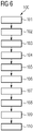
- FIG. 6 schematically depicts the steps 101 - 110 of the method 100 for manufacturing the composite part 20 with the dry spot by means of the vacuum assisted resin transfer molding using the dry spot arrangement 40 from FIGS. 4 and 5 and as previously explained.
- the mold 24 is provided.
- the mold 24 is provided with a shape that corresponds to the shape of the composite part 20 that is to be manufactured.
- the composite part 20 may be a rotor blade for a wind turbine or part thereof.
- the mold 24 has a curved shape corresponding to a curvature of a rotor blade.
- step 102 of method 100 the reinforcement material 22.1, 22.2, 22.3, 22.4 is placed on the mold 24 in the desired number of layers and fiber orientation.
- step 103 of method 100 the peel-ply 26 is placed on top of the already placed reinforcement material 22.1, 22.2, 22.3, 22.4.
- the peel-ply 26 enables uniform infusion of the layup with the liquid matrix material 23 and simple removal of the seal cover 25 attached to the layup of the composite material 20 after curing the infused layup to get the composite material 20.
- step 104 of method 100 the dry spot tool 1 and the controlled leak system 13 are provided on the peel-ply 26 as previously explained with reference to FIG. 5 .
- step 105 of method 100 the seal cover 25 is placed on top of the entirety of the layup of the composite part 20 to be manufactured including the dry spot tool 1 and the suction structure 13 in the opening 6.
- step 106 of method 100 the hoses 11.1, 11.2 connected to the vacuum system 30 are connected through or, in other words, penetrating the seal cover 25 to the nozzles 9 of the dry spot tool 1.
- the hose 11.3 is being connected to the suction structure 14, and the hoses 11.4, 11.5 of the reservoir 32 and the additional vacuum system 31 are connected via the matrix material inlet 32 and matrix material outlet 31 (see FIG. 4 ) to the first space 26 inside of the layup of the composite part 20 to be manufactured.
- both vacuum systems 30, 31 are operated such that the layup of the composite part 20 outside of the tool body 20 is infused with the resin from the reservoir 32 during the vacuum assisted resin transfer molding executed thereby, while the layup of the composite part 20 at the position of the opening 6 remains dry, such that the dry spot 21 shown in FIG. 7 is formed in the composite part 20 that is thereby manufactured.
- step 108 of method 100 the vacuum systems 30, 31 are turned off and the liquid matrix material 23 inside of the layup of the composite part 20 is allowed to cure for a predetermined time period.
- step 109 of method 100 the seal cover 25 together with the peel-ply 26, the dry spot tool 1 and the suction structure 14 are removed from the manufactured composite part 20 consisting of the reinforcement material 22.1, 22.2, 22.3, 22.4 and the cured matrix material 23.
- the composite part 20 is also removed from the mold 24.
- a hole is cut in the composite part 20 in the area of the dry spot 21 seen in FIG. 7 .
- the hole may serve for a function of the composite part 20, which in this case is a rotor blade of a wind turbine.
- an attachment of a lifting device via the hole, guiding supply hoses of aerodynamic features placed on a blade surface of the rotor blade through the hole or guiding a lightning protection receptor from the blade surface through the hole are some possible further steps of application involving the hole cut in the area of the dry spot 21.
- FIG. 8 shows the cross-sectional cut along line A-A of FIG. 7 .
- the manufactured composite part 20 is seen with the cured portions having the cured matrix material 23 embedding the reinforcement material 22.1, 22.2, 22.3, 22.4 therein and a portion in between, which is the dry spot 21.
- the dry spot 21 has the reinforcement material 22.1, 22.2, 22.3, 22.4 but not the matrix material 23 embedding the fibers of the reinforcement material 22.1, 22.2, 22.3, 22.4 therein.
Landscapes
- Chemical & Material Sciences (AREA)
- Engineering & Computer Science (AREA)
- Composite Materials (AREA)
- Mechanical Engineering (AREA)
- Casting Or Compression Moulding Of Plastics Or The Like (AREA)
- Moulding By Coating Moulds (AREA)
Abstract
Description
- The invention relates to a dry spot tool for creating a dry spot in a composite material of a wind turbine during vacuum assisted resin transfer molding, a dry spot arrangement comprising the dry spot tool and a vacuum system and a method for manufacturing a composite part with a dry spot by means of vacuum assisted resin transfer molding using the dry spot arrangement.
- In geometrically complex and large composite parts, such as rotor blades of wind turbines, which are manufactured by a liquid composite molding process, formation of unintended dry spots resulting from macroscopic gas entrapments during the manufacturing process may occur. The formation of one or several dry spots in the composite part is a problem because it may lead to scrap parts.
- It is desirable to gain control of the formation of dry spots in the manufacturing process of composite parts. Thereby, it would be possible to analyze the phenomenon of the macroscopic gas entrapments more thoroughly, eventually leading to a better understanding of the formation of the dry spots, in particular in specific composite structures and geometries, and avoidance during appropriate setup and control of the manufacturing process.
- Moreover, the inventors have found that an intended and controlled dry spot formation, in particular with respect to size and location of the dry spot, may provide advantageous composite parts, in which the dry spots may fulfil certain functions of the unit, for example a wind turbine, in which the manufactured composite part is later used.
- Accordingly, it is an object of the invention to enable a controlled creation of dry spots in a composite part during vacuum assisted resin transfer molding, which should be simple and inexpensive.
- This object is solved by the subject-matter of the claims. In particular, the object is solved by a dry spot tool according to
claim 1, a dry spot arrangement according to claim 9 and a method for manufacturing a composite part with a dry spot by means of vacuum assisted resin transfer molding using the dry spot arrangement according toclaim 14. Further details of the invention unfold from the other claims as well as the description and the drawings. Thereby, the features and details described in connection with the dry spot tool of the invention, the dry spot arrangement of the invention and the method of the invention apply in connection with each other so that regarding the disclosure of the individual aspects of the invention, it is or can be referred to one another. - According to a first aspect of the invention, the above object is solved by a dry spot tool for creating a dry spot in a composite part of a wind turbine during vacuum assisted resin transfer molding. The dry spot tool has a tool body. The tool body comprises a perimeter. The tool body extends along the perimeter and has an opening in the center of the perimeter for creating the dry spot in an area of the opening. The tool body further has a top side and a bottom side. The top side is opposite of the bottom side and the bottom side has at least one bottom surface. The tool body also has outlets. The outlets are fluidically connected to inlets of the dry spot tool. The inlets are configured for connecting hoses of a vacuum system thereto. Further, the tool body comprises a flow passage. The flow passage fluidically connects the outlets with one another. Also, the flow passage extends at least for a partial length thereof along the perimeter of the tool body. Moreover, the flow passage extends at least for a partial length thereof in width from the outlets to the bottom side.
- The usage of the dry spot tool allows the creation of dry spots in the composite part during the manufacturing process of vacuum assisted resin transfer molding. This may be done by placing the dry spot tool on top of a reinforcement material, in particular fiber material and having multiple layers, which may be placed on top of a mold or draped onto the mold. A seal cover may afterwards be placed on both, the reinforcement material and the dry spot tool. The dry spot tool may then be attached to the vacuum system. Then, the space between the mold and the seal cover may be supplied with liquid matrix material, in particular resin, by means of applying a vacuum for infusing the reinforcement material with the liquid matrix material as generally known in the state of the art. During this process, which in the art is generally referred to as vacuum assisted resin transfer molding, vacuum may be supplied to the dry spot tool by means of the vacuum system. This vacuum provides for firm attachment of the dry spot tool to the reinforcement material. More particularly, a vacuum is created inside of the flow passage connected via the outlets to the inlets connected to the vacuum system. The bottom side of the dry spot tool with the vacuum inside the flow passage accordingly may press against the mold having the reinforcement material in between and attach with its at least one bottom surface to the reinforcement material and mold. The tool body thereby prevents the liquid matrix material from flowing from outside of the dry spot tool into the inside of the dry spot tool defined by its opening during the vacuum assisted infusion process. After the infusion process has finished, the area outside of the dry spot tool is soaked or wetted with the liquid matrix material and may cure. However, the area inside of the opening of the dry spot tool has remained dry during the manufacturing process, thereby resulting in the dry spot. The use of the dry spot tool will be described later in more detail with reference to the manufacturing method making use of the dry spot tool.
- The dry spot tool thereby allows for a particular simple and inexpensive method of creating a dry spot in a controlled manner. The dry spot tool may essentially create the dry spot at any location of the composite material and in any size. For adjusting the location of the dry spot, the dry spot tool may essentially be placed on any area of the matrix reinforcement material or mold. For adjusting the size of the dry spot to be created, the opening or overall dry spot tool may be dimensioned according to the desired dry spot size.
- The dry spot tool is not limited to flat or planar geometries of the mold or composite part to be manufactured but may be adjusted in the shape of its tool body to correspond to the geometry of the mold or composite part at the location at which the dry spot is to be created. For example, the tool body, in particular its bottom side, may be curved or have one or multiple edges. For example, if the composite part to be manufactured is a rotor blade of a wind turbine and the dry spot is to be created on the leading edge of the rotor blade, the tool body may be designed with its geometry corresponding to the geometry of the leading edge at the location in which the dry spot is to be created in the rotor blade made from the composite material.
- The tool body or the entire dry spot tool may be designed monolithically or, in other words, from a single piece of material. It is preferable that the dry spot tool is made from plastic, which is particularly inexpensive. Preferably, the tool body or the entire dry spot tool may be manufactured by an additive manufacturing process, which allows to manufacture the dry spot tool with great freedom with respect to its geometry and inexpensively provide different dry spot tools for different places of dry spots to be created on geometrically complex composite parts.
- The at least one bottom surface on the bottom side of the tool body may be a substantially smooth surface. Thereby, it may be prevented that gaps occur between the reinforcement material and the tool body, which might allow the liquid matrix material to enter the inside of the dry spot tool, eventually resulting in an undesired infusion of the area inside of the dry spot tool, where the dry spot shall be created.
- A particular preferable application of the dry spot tool is in manufacturing processes of composite parts of wind turbines, such as rotor blades, for example, as these are comparatively large, may have complex geometry and are therefore difficult to manufacture. Also, the dry spot in the composite parts of wind turbines may fulfill different functions associated with the wind turbine, as will be explained in more detail later on. However, the dry spot tool may be used for other composite parts than from wind turbines as well and the dry spot tool and its associated method for manufacturing a composite part with a dry spot are not limited to composite parts of wind turbines. The composite part may alternatively be of any other structure, such as, for example, a car, an airplane, or similar.
- The flow passage may substantially extend along the entire perimeter of the tool body. Substantially herein means that the flow passage extends along the entire or nearly the entire perimeter, in particular along at least 95 % of the perimeter, of the tool body. When the flow passage substantially extends along the entire perimeter of the tool body, the vacuum generated inside of the flow passage may completely or nearly completely attach the tool body to the reinforcement material on which it may be placed. Thereby, it may be prevented that a gap between the tool body and reinforcement material allows liquid matrix material to flow from outside of the dry spot tool into the inside or opening thereof, which would result in undesired infusion of the area inside of the dry spot tool.
- The flow passage may extend substantially along its entire length in width from the outlets to the bottom side. Substantially herein means that the flow passage extends along its entire length or nearly its entire length in width from the outlets to the bottom side, in particular along at least 95 % of its length. When the flow passage substantially extends along its entire length in width from the outlets to the bottom side, the vacuum generated inside of the flow passage may completely or nearly completely attach the tool body to the reinforcement material on which it may be placed. Thereby, it may be prevented that a gap between the tool body and reinforcement material allows liquid matrix material to flow from outside of the dry spot tool into the inside or opening thereof, which would result in undesired infusion of the area inside of the dry spot tool.
- The flow passage may extend from an inside of the tool body, in which the outlets are located, to the bottom side. For example, the flow passage may be designed as a cavity or groove inside of the tool body. The cavity or groove may be open towards or at the bottom side such that the flow passage extends in width to the bottom side. The width or, in other words, diameter of the dry spot tool is understood as the extension of the flow passage perpendicular to its length or, in other words, longitudinal extension.
- The bottom side may have two bottom surfaces separated from one another by means of the flow passage located in between the two bottom surfaces. In particular, the two bottom surfaces may be part of two separate walls of the tool body, in between which the flow passage, in particular cavity or groove, extends. The two bottom surfaces may share one common level or plane. In the manufacturing process, the flow passage with its open side is being (nearly) closed by sucking onto the mold or reinforcement material functioning as a closure, whereas the two bottom surfaces attach to the mold or reinforcement material effectively shutting off the flow passage from the outside of the dry spot tool and the inside or opening of the dry spot tool. The two bottom surfaces very effectively prevent the liquid matrix material flowing outside of the dry spot tool from flowing into the opening of the dry spot tool, because there are two walls which would need to be passed by the liquid matrix material to get into the area of the dry spot to be created.
- Each one of the inlets may be respectively fluidically connected to one of the outlets via a respective one of multiple flow channels. The flow channels may be at least partially provided in the tool body. The inlets may in particular be provided on the top side of the tool body.
- The dry spot tool may comprise nozzles extending away from the top side of the tool body. Each one of the nozzles may have one of the inlets of the dry spot tool. The number of nozzles may correspond to the number of outlets. The number of nozzles may be two, three, four or more, for example. The nozzles may be spatially distributed with equal distance from one another on the dry spot tool. Also, or alternatively, the inlets and/or outlets may be spatially distributed with equal distance from one another on the dry spot tool. The individual flow channels may, in addition to being formed inside of the tool body, also be formed inside of the nozzles, thereby extending along the nozzles and the tool body. The nozzles may be made separate from the tool body and attached to the tool body. In particular, the nozzles may be made from a different material than the tool body. For example, the nozzles may be made from a flexible material, allowing flexibility for attaching the hoses of the vacuum system thereto. For example, rubber may be chosen as a flexible material. Alternatively, the nozzles may be monolithically or, in other words, integrally formed with the tool body.
- The tool body may have a substantially circular, square or triangular shape, for example. The circular shape of the tool body preferably allows for a good distribution of the negative pressure generated by the vacuum system. When the opening has a circular shape as well, the dry spot may be provided as a circular dry spot. This may be preferred for certain applications. A circular-shaped tool body with a central opening having a circular shape results in a ring-shaped tool body. Alternatively, the opening of the tool body may have a square or triangular shape, which may correspond to the geometrical shape of the tool body. Thereby, different shapes of dry spots may be created depending on the particular requirement or later application of the dry spot of the composite part or component.
- According to a second aspect of the invention, the object is solved by a dry spot arrangement comprising the dry spot tool according to the first aspect of the invention. The dry spot arrangement further comprises hoses and a vacuum system. The vacuum system is configured to be connected or is connected to the inlets of the dry spot tool via the hoses.
- Each one of the inlets of the dry spot tool may be individually connected to the vacuum system via an individual one of the hoses, for example. It is possible that the individual hoses are connected with each other before being connected to the vacuum system. The vacuum system may in particular be a vacuum pump.
- The dry spot arrangement may further comprise an additional vacuum system and a reservoir. The additional vacuum system may be decoupled from the vacuum system (connected to the dry spot tool) such that the vacuum systems may be operated with different negative pressures. The reservoir may comprise a liquid matrix material. In particular, each one of the vacuum systems may be an individual vacuum pump, which may be individually operated. Alternatively, the vacuum systems may be provided by means of a single vacuum pump but there may be a regulating device, such as a valve, enabling the vacuum pump to provide the vacuum systems with different negative pressures.
- The additional vacuum system may be configured to be operated with a greater negative pressure than the vacuum system (connected to the dry spot tool). This ensures that the liquid matrix material may be evenly distributed along the entire reinforcement material outside of the dry spot tool without interruption from the vacuum generated by the vacuum system attached to the dry spot tool. In particular, it may be prevented that the vacuum system connected to the dry spot tool draws the liquid matrix material inside of the opening of the dry spot tool, where the dry spot shall be created.
- The dry spot arrangement may further comprise a controlled leak system. The controlled leak system may have a suction structure configured to be placed or being placed inside of the opening. The suction structure may be a suction cup, for example. The leak or leakage provided at the opening of the dry spot tool ensures provision of the dry spot tool with a continuous negative pressure, thereby preventing the liquid matrix material from entering the area of the opening of the tool body during the resin transfer molding or, in other words, infusion process.
- The controlled leak system may have a control device for controlling a leak flow of the dry spot arrangement passing through the suction structure. The control device allows for regulating the negative pressure inside of the dry spot tool. The control device may be a clamp, for example.
- According to a third aspect of the invention, the object is solved by a method for manufacturing a composite part, in particular of a wind turbine, with a dry spot by means of vacuum assisted resin transfer molding using the dry spot arrangement of the second aspect of the invention. The method comprises the steps of:
- providing a mold;
- placing reinforcement material on the mold;
- placing the dry spot tool on the reinforcement material;
- sealing the dry spot tool and the reinforcement material by means of a seal cover;
- generating a negative pressure in a first space between the mold and the seal cover outside of the dry spot tool, thereby infusing the first space with the liquid matrix material; and
- generating a negative pressure in a second space between the mold and the seal cover inside of the dry spot tool, thereby creating the dry spot in the composite material manufactured by curing the infused liquid matrix material.
- The manufacturing method may comprise further steps as generally known to the person skilled in the art to be applied in a vacuum assisted resin transfer molding. Such a further step may be placing a peel-ply (and distribution layer) on the reinforcement material, for example. Also, the method may comprise the step of sealing the seal cover, e.g., by means of a sealant tape. A further step may be to provide the additional vacuum system, in particular an additional vacuum pump, and fluidically attach it to the first space. Also, a further step may be to provide the reservoir with the liquid matrix material, in particular resin, and fluidically attach it to the first space. The negative pressure in the first space may be generated by operating the additional vacuum system. The curing of the liquid matrix material may be performed by waiting for a certain curing time.
- The manufacturing method may moreover comprise further steps specifically designed for the dry spot creation as described herein. For example, the method may as a further step comprise providing the vacuum system, in particular a vacuum pump, and fluidically attaching it to the dry spot tool. The negative pressure in the second space may be generated by means of the vacuum system. The negative pressure in the second space may in particular be less than the negative pressure in the first space.
- The method may further comprise providing the controlled leak system as previously described. The suction structure may be placed inside of the opening and attached to the reinforcement material. Accordingly, the dry spot tool and the reinforcement material may later together with the suction structure be sealed by means of the seal cover. The leakage flow of the dry spot arrangement passing through the suction structure may be controlled by means of the control device.
- The method may further comprise the step of cutting a hole into the composite part in the area of the dry spot. The cutting of the hole in the dry spot area after the composite part has been manufactured is much easier than in the wet or infused area of the composite part. Also, the precision of the hole cutting may be increased. The hole may later serve for a function of the composite part. For example, in the case that the composite part is a rotor blade of a wind turbine, the hole or multiple holes cut into dry spot areas may serve as attachment points of lifting devices, introduction points of supply hoses of aerodynamic features placed on a blade surface of the rotor blades or for guiding lightning protection receptors from the blade surface therethrough.
- Further advantages, features and details of the invention unfold from the following description, in which by reference to drawings
FIGS. 1 - 8 , embodiments of the present invention are described in detail. Thereby, the features from the claims as well as the features mentioned in the description can be essential for the invention as taken alone or in an arbitrary combination. In the drawings, there is schematically shown: - FIG. 1
- a perspective view on a top side of a dry spot tool;
- FIG. 2
- a perspective view on a bottom side of the dry spot tool from
FIG. 1 ; - FIG. 3
- a perspective view on the dry spot tool of
FIGS. 1 and 2 and a controlled leak system used during vacuum assisted resin transfer molding of a composite part; - FIG. 4
- a top view on a vacuum assisted resin transfer molding process including a dry spot arrangement having the dry spot tool of
FIG. 3 ; - FIG. 5
- a side view on the vacuum assisted resin transfer molding process depicted in
FIG. 4 ; - FIG. 6
- a schematic illustration of the steps of the vacuum assisted resin transfer molding process performed in
FIGS. 4 and5 ; - FIG. 7
- a top view on the composite part manufactured by means of the vacuum assisted resin transfer molding process depicted in
FIGS. 4 - 6 ; and - FIG. 8
- a sectional view of the composite part of
FIG. 7 . - Same objects in
FIGS. 1 - 8 are denominated with the same reference number. If there is more than one of the same type of object in any one of theFIGS. 1 - 8 , the objects of the same type are denominated with the same reference number, whereby the objects are numbered in ascending order, the numbering being separated from the reference number by a dot. The objects are shown in a schematic manner and their specific dimensions are exemplary and may be enlarged for ease of reference only. -
FIG. 1 shows adry spot tool 1 having atool body 2. Thedry spot tool 1 is configured for creating adry spot 21 in a composite part 20 (seeFIG. 7 ) during a manufacturing process of thecomposite part 20 including vacuum assisted resin transfer molding. - The
dry spot tool 1 has anopening 6 inside of it. In this example of adry spot tool 1, thetool body 2 has a ring-shape surrounding theopening 6. However, thetool body 2 is not limited to this ring-shape or any other circular shape but may alternatively have a square shape, triangular shape or similar. - The
dry spot tool 1 has atop side 3, which may be seen inFIG. 1 . A number of nozzles 9.1, 9.2, 9.3, 9.4 are provided on thetop side 3, which extend away from thetop side 3. In this case, there are four nozzles 9.1, 9.2, 9.3, 9.4 as well as four outlets 7.1, 7.2, 7.3, 7.4 and inlets 10.1, 10.2, 10.3, 10.4 provided on thedry spot tool 1. At their ends, the nozzles 9.1, 9.2, 9.3, 9.4 are provided with inlets 10.1, 10.2, 10.3, 10.4. The nozzles 9.1, 9.2, 9.3, 9.4 enable a simple and air-tight connection of hoses 11.1, 11.2, 11.3, 11.4 (seeFIG. 3 ) thereto. - The nozzles 9.1, 9.2, 9.3, 9.4 of the
dry spot tool 1 shown inFIG. 1 are manufactured separately and later attached to thetool body 2. However, it is also possible to manufacture thetool body 2 with the nozzles 9.1, 9.2, 9.3, 9.4 or, in other words, the entiredry spot tool 1 from the same material and in one single manufacturing process, for example from a plastic and by means of additive manufacturing. -
FIG. 2 shows thedry spot tool 1 with its bottom side 4, which is opposite of thetop side 3. Thedry spot tool 1 has a number of outlets 7.1, 7.2, 7.3, 7.4 equivalent to the number of nozzles 9.1, 9.2, 9.3, 9.4 or inlets 10.1, 10.2, 10.3, 10.4, which are fluidically connected with each other through respective flow channels extending inside of thetool body 2 and the nozzles 9.1, 9.2, 9.3, 9.4. - On the bottom side 4, the
dry spot tool 1 further has aflow passage 8. In this exemplary case, theflow passage 8 extends with its entire length L along a perimeter P of thetool body 2. Further, theflow passage 8 extends in width or diameter from the outlets 7.1, 7.2, 7.3, 7.4 inside of thetool body 2 to the bottom side 4. - The
flow passage 8 in this exemplary case follows the ring-shape of thetool body 2. Theflow passage 8 is designed as a groove or cavity inside of thetool body 2 at its bottom side 4, and it is fluidically connected to each one of the outlets 7.1, 7.2, 7.3, 7.4. In other words, each one of the outlets 7.1, 7.2, 7.3, 7.4 fluidically connects with the other ones via theflow passage 8. - The
flow passage 8 separates two bottom surfaces 5.1, 5.2 of the bottom side 4 from one another, the two bottom surfaces 5.1, 5.2 sharing the same plane. Theflow passage 8 extends between the two bottom surfaces 5.1, 5.2 along the bottom side 4, such that the inner bottom surface 5.1 is adjacent theopening 6 and the outer bottom surface 5.2 is adjacent the outside of thetool body 2. -
FIG. 3 shows thedry spot tool 1 ofFIGS. 1 and 2 together with a controlledleak system 13 during the vacuum assisted resin transfer molding process. Thedry spot tool 1 with itstool body 2 is placed on a layup of thecomposite part 20. - The layup of the
composite part 20 comprise reinforcement material 22 (seeFIG. 5 ), which may comprise multiple reinforcement material layers and be made from fibers or, in other words, the reinforcement material 22 may be a fibrous material having multiple layers stacked on top of one another. The reinforcement material 22 may comprise glass fibers, aramid fibers, carbon fibers and/or other fibers for reinforcing thecomposite part 20 to be manufactured. - Hoses 11.1, 11.2, 11.3, 11.4 are individually attached to the nozzles 9.1, 9.2, 9.3, 9.4 of the
dry spot tool 1. Adhesive tapes 12.1, 12.2, 12.3, 12.4 assist in the sealing attachment of the hoses 11.1, 11.2, 11.3, 11.4 to the nozzles 9.1, 9.2, 9.3, 9.4. - A
suction structure 14 of the controlledleak system 13, which in this exemplary case is a suction cup, has been placed on the layup of thecomposite part 20. Thesuction structure 14 is attached to a hose 11.5, to which acontrol device 16, which in this exemplary case is a clamp, is attached. An outer rim of thesuction structure 14 is sealingly attached to the reinforcement material 22 of thecomposite part 20 by means of an adhesive 15. -
FIG. 4 further shows that the hoses 11.1, 11.2, 11.3, 11.4 are connected to avacuum system 30, which in this exemplary case is anindividual vacuum pump 30, thereby forming adry spot arrangement 40 including thedry spot tool 1. - The layup consisting of the components shown in
FIG. 5 for manufacturing thecomposite part 20 is fluidically connected to areservoir 32 containing a liquid matrix material 23 (seeFIG. 5 ), in particular resin, via a further hose 11.7 and amatrix material inlet 34 on the layup of the composite part. A further oradditional vacuum system 31, which in this exemplary case is designed as a further oradditional vacuum pump 31, is connected via a further hose 11.6 and amatrix material outlet 33 to the layup of thecomposite part 20 to be manufactured. - In the example of
FIG. 4 , thedry spot tool 1 is arranged in the center of thecomposite part 20. However, thedry spot tool 1 may be arranged anywhere on the layup of thecomposite part 20. Also, it is possible to provide multipledry spot tools 1 on the same layup of thecomposite part 20. Thesame vacuum system 30 may be used for all of these multipledry spot tools 1. - Further, in the example of
FIG. 4 , only onematrix material inlet 34 and onematrix material outlet 33 are shown. However, there may be multiplematrix material inlets 34 and/or multiplematrix material outlets 33 distributed throughout the area of the layup of thecomposite part 20 to be manufactured, in particular at its sides. Thereby, an even infusion or, in other words, wetting of the reinforcement material 22 with theliquid matrix material 23 may be ensured throughout the reinforcement material 22, in particular around the area where thedry spot tool 1 is placed. -
FIG. 5 shows the manufacturing setup according toFIG. 4 from another perspective. The layup of thecomposite part 20 to be manufactured consists of multiples layers of reinforcement material 22.1, 22.2, 22.3, 22.4 placed on top of one another on themold 24. In this case, the fibers of the layers of reinforcement material 22.1, 22.2, 22.3, 22.4 are oriented in different directions as may be seen inFIG. 5 . A peel-ply 26 is placed on top of the reinforcement material 22.1, 22.2, 22.3, 22.4. - The
tool body 2 and thesuction structure 13 are placed on top of the reinforcement material 22.1, 22.2, 22.3, 22.4 and the peel-ply 26. Thetool body 2, thesuction structure 13, the reinforcement material 22.1, 22.2, 22.3, 22.4 together with the peel ply 26 and themold 24 underneath are then covered by aseal cover 25. In this exemplary case, theseal cover 25 is a vacuum bag. The vacuum bay may be made from a plastic material, in particular a transparent plastic material, for example. - After the
tool body 2 and thesuction structure 13 have been covered with theseal cover 25, they are connected by means of the hoses 11.1, 11.2 (only these are shown inFIG. 5 for the sake of simplicity) as shown inFIG. 4 to thevacuum system 30. Because the nozzles 9.1, 9.2, 9.3, 9.4 are fluidically connected to theflow passage 8 at the bottom side 4 of thetool body 2 and due to the controlled leak provided by the controlledleak system 13, the hoses 11.1, 11.2 of thevacuum system 30 are thereby connected to asecond space 26 between theseal cover 25 and themold 24 inside of theopening 6 of thetool body 2. - When the
vacuum system 30 is operated, it draws air from within thesecond space 26 constantly provided by means of the controlledleak system 13, and thetool body 2 is pressed against themold 24. Thereservoir 32 andadditional vacuum system 31 are being operated in parallel and infuse the layup of thecomposite part 20 between themold 24 and theseal cover 25 with theliquid matrix material 23 outside of thetool body 2. Theadditional vacuum system 31 is being operated with a greater negative pressure than thevacuum system 30 such that theliquid matrix material 23 is distributed throughout the area of the layup of thecomposite part 20 outside of thetool body 2 rather than inside of theopening 6. The negative pressure from thevacuum system 30 presses thetool body 2 firmly against the layup of thecomposite part 20 andmold 24 at its position and through the constantly provided negative pressure preventsliquid matrix material 23 from entering thesecond space 27 inside of theopening 6. -
FIG. 6 schematically depicts the steps 101 - 110 of themethod 100 for manufacturing thecomposite part 20 with the dry spot by means of the vacuum assisted resin transfer molding using thedry spot arrangement 40 fromFIGS. 4 and5 and as previously explained. - In
step 101 ofmethod 100, themold 24 is provided. Themold 24 is provided with a shape that corresponds to the shape of thecomposite part 20 that is to be manufactured. In this case, thecomposite part 20 may be a rotor blade for a wind turbine or part thereof. As may be seen inFIG. 5 , themold 24 has a curved shape corresponding to a curvature of a rotor blade. - In
step 102 ofmethod 100, the reinforcement material 22.1, 22.2, 22.3, 22.4 is placed on themold 24 in the desired number of layers and fiber orientation. - In
step 103 ofmethod 100, the peel-ply 26 is placed on top of the already placed reinforcement material 22.1, 22.2, 22.3, 22.4. The peel-ply 26 enables uniform infusion of the layup with theliquid matrix material 23 and simple removal of theseal cover 25 attached to the layup of thecomposite material 20 after curing the infused layup to get thecomposite material 20. - In
step 104 ofmethod 100, thedry spot tool 1 and the controlledleak system 13 are provided on the peel-ply 26 as previously explained with reference toFIG. 5 . - In
step 105 ofmethod 100, theseal cover 25 is placed on top of the entirety of the layup of thecomposite part 20 to be manufactured including thedry spot tool 1 and thesuction structure 13 in theopening 6. - In
step 106 ofmethod 100, the hoses 11.1, 11.2 connected to thevacuum system 30 are connected through or, in other words, penetrating theseal cover 25 to the nozzles 9 of thedry spot tool 1. Similarly, the hose 11.3 is being connected to thesuction structure 14, and the hoses 11.4, 11.5 of thereservoir 32 and theadditional vacuum system 31 are connected via thematrix material inlet 32 and matrix material outlet 31 (seeFIG. 4 ) to thefirst space 26 inside of the layup of thecomposite part 20 to be manufactured. - In
step 107 ofmethod 100, bothvacuum systems composite part 20 outside of thetool body 20 is infused with the resin from thereservoir 32 during the vacuum assisted resin transfer molding executed thereby, while the layup of thecomposite part 20 at the position of theopening 6 remains dry, such that thedry spot 21 shown inFIG. 7 is formed in thecomposite part 20 that is thereby manufactured. - In
step 108 ofmethod 100, thevacuum systems liquid matrix material 23 inside of the layup of thecomposite part 20 is allowed to cure for a predetermined time period. - In
step 109 ofmethod 100, theseal cover 25 together with the peel-ply 26, thedry spot tool 1 and thesuction structure 14 are removed from the manufacturedcomposite part 20 consisting of the reinforcement material 22.1, 22.2, 22.3, 22.4 and the curedmatrix material 23. Thecomposite part 20 is also removed from themold 24. - In optional step 110 of
method 100, a hole is cut in thecomposite part 20 in the area of thedry spot 21 seen inFIG. 7 . In a possible further step, the hole may serve for a function of thecomposite part 20, which in this case is a rotor blade of a wind turbine. For example, an attachment of a lifting device via the hole, guiding supply hoses of aerodynamic features placed on a blade surface of the rotor blade through the hole or guiding a lightning protection receptor from the blade surface through the hole are some possible further steps of application involving the hole cut in the area of thedry spot 21. -
FIG. 8 shows the cross-sectional cut along line A-A ofFIG. 7 . The manufacturedcomposite part 20 is seen with the cured portions having the curedmatrix material 23 embedding the reinforcement material 22.1, 22.2, 22.3, 22.4 therein and a portion in between, which is thedry spot 21. Thedry spot 21 has the reinforcement material 22.1, 22.2, 22.3, 22.4 but not thematrix material 23 embedding the fibers of the reinforcement material 22.1, 22.2, 22.3, 22.4 therein.
Claims (15)
- Dry spot tool (1) for creating a dry spot (21) in a composite part (20) of a wind turbine during vacuum assisted resin transfer molding, whereby the dry spot tool (1) has a tool body (2) comprising:- a perimeter (P), the tool body (2) extending along the perimeter (2) and having an opening (6) in the center of the perimeter (2) for creating the dry spot (21) in an area of the opening (6);- a top side (3) and a bottom side (4), the top side (3) being opposite of the bottom side (4) and the bottom side (4) having at least one bottom surface (5);- outlets (7), the outlets (7) being fluidically connected to inlets (10) of the dry spot tool (1), the inlets (10) being configured for connecting hoses (11) of a vacuum system (30) thereto; and- a flow passage (8), the flow passage (8) fluidically connecting the outlets (7) with one another, extending at least for a partial length (L) thereof along the perimeter (P) of the tool body (2) and extending at least for a partial length (L) thereof in width from the outlets (7) to the bottom side (4).
- Dry spot tool (1) according to claim 1, whereby the flow passage (8) substantially extends along the entire perimeter (P) of the tool body (2).
- Dry spot tool (1) according to claim 1 or 2, whereby the flow passage (8) extends substantially along its entire length (L) in width from the outlets (7) to the bottom side (4).
- Dry spot tool (1) according to any of the previous claims, whereby the flow passage (8) extends from an inside of the tool body (2), in which the outlets (7) are located, to the bottom side (4).
- Dry spot tool (1) according to any of the previous claims, whereby the bottom side (4) has two bottom surfaces (5) separated from one another by means of the flow passage (8) located in between the two bottom surfaces (5).
- Dry spot tool (1) according to any of the previous claims, whereby each one of the inlets (10) is respectively fluidically connected to one of the outlets (7) via a respective one of multiple flow channels.
- Dry spot tool (1) according to any of the previous claims, whereby the dry spot tool (1) comprises nozzles (9) extending away from the top side (3) of the tool body (2), each one of the nozzles (9) having one of the inlets (10) of the dry spot tool (1).
- Dry spot tool (1) according to any of the previous claims, whereby the tool body (2) has a substantially circular, square or triangular shape.
- Dry spot arrangement (40) comprising the dry spot tool (1) according to any of the previous claims, hoses (11) and a vacuum system (30), the vacuum system (30) being configured to be connected or being connected to the inlets (10) of the dry spot tool (1) via the hoses (11).
- Dry spot arrangement (40) according to claim 9, whereby the dry spot arrangement (40) further comprises an additional vacuum system (31) and a reservoir (32), the additional vacuum system (31) being decoupled from the vacuum system (30) such that the vacuum systems (30, 31) may be operated with different negative pressures and the reservoir (32) comprising a liquid matrix material (23).
- Dry spot arrangement (40) according to claim 10, whereby the additional vacuum system (31) is configured to be operated with a greater negative pressure than the vacuum system (30).
- Dry spot arrangement (40) according to any of claims 9 - 11, whereby the dry spot arrangement (40) further comprises a controlled leak system (13), the controlled leak system (13) having a suction structure (14) being configured to be placed or being placed inside of the opening (6).
- Dry spot arrangement (40) according to claim 12, whereby the controlled leak system (13) comprises a control device (16) for controlling a leak flow of the dry spot arrangement (40) passing through the suction structure (14).
- Method (100) for manufacturing a composite part (20) with a dry spot (21) by means of vacuum assisted resin transfer molding using the dry spot arrangement (40) according to any of claims 10 - 13, whereby the method (100) comprises the steps of:- providing a mold (24);- placing reinforcement material (22) on the mold (24);- placing the dry spot tool (1) on the reinforcement material (22);- sealing the dry spot tool (1) and the reinforcement material (22) by means of a seal cover (25);- generating a negative pressure in a first space (26) between the mold (24) and the seal cover (25) outside of the dry spot tool (1), thereby infusing the first space (26) with the liquid matrix material (23); and- generating a negative pressure in a second space (27) between the mold (24) and the seal cover (25) inside of the dry spot tool (1), thereby creating the dry spot (21) in the composite material (20) manufactured by curing the infused liquid matrix material (23).
- Method (100) according to claim 14, whereby the method (100) further comprises the step of cutting a hole into the composite part (20) in the area of the dry spot (21).
Priority Applications (2)
| Application Number | Priority Date | Filing Date | Title |
|---|---|---|---|
| DK21174154.1T DK4091802T3 (en) | 2021-05-17 | 2021-05-17 | Dry spot tool for creating a dry spot in a composite part |
| EP21174154.1A EP4091802B1 (en) | 2021-05-17 | 2021-05-17 | Dry spot tool for creating a dry spot in a composite part |
Applications Claiming Priority (1)
| Application Number | Priority Date | Filing Date | Title |
|---|---|---|---|
| EP21174154.1A EP4091802B1 (en) | 2021-05-17 | 2021-05-17 | Dry spot tool for creating a dry spot in a composite part |
Publications (2)
| Publication Number | Publication Date |
|---|---|
| EP4091802A1 true EP4091802A1 (en) | 2022-11-23 |
| EP4091802B1 EP4091802B1 (en) | 2026-01-28 |
Family
ID=75936898
Family Applications (1)
| Application Number | Title | Priority Date | Filing Date |
|---|---|---|---|
| EP21174154.1A Active EP4091802B1 (en) | 2021-05-17 | 2021-05-17 | Dry spot tool for creating a dry spot in a composite part |
Country Status (2)
| Country | Link |
|---|---|
| EP (1) | EP4091802B1 (en) |
| DK (1) | DK4091802T3 (en) |
Citations (3)
| Publication number | Priority date | Publication date | Assignee | Title |
|---|---|---|---|---|
| US20120292408A1 (en) * | 2011-05-18 | 2012-11-22 | Delavan Inc. | Multipoint injectors with standard envelope characteristics |
| EP2871047A1 (en) * | 2013-11-07 | 2015-05-13 | Siemens Aktiengesellschaft | Wind turbine blade segment and method of manufacturing the wind turbine blade segment |
| CN107576219A (en) * | 2017-09-06 | 2018-01-12 | 河北科技大学 | A kind of combination tubular sheet heat exchanger with thermal compensation function |
-
2021
- 2021-05-17 EP EP21174154.1A patent/EP4091802B1/en active Active
- 2021-05-17 DK DK21174154.1T patent/DK4091802T3/en active
Patent Citations (3)
| Publication number | Priority date | Publication date | Assignee | Title |
|---|---|---|---|---|
| US20120292408A1 (en) * | 2011-05-18 | 2012-11-22 | Delavan Inc. | Multipoint injectors with standard envelope characteristics |
| EP2871047A1 (en) * | 2013-11-07 | 2015-05-13 | Siemens Aktiengesellschaft | Wind turbine blade segment and method of manufacturing the wind turbine blade segment |
| CN107576219A (en) * | 2017-09-06 | 2018-01-12 | 河北科技大学 | A kind of combination tubular sheet heat exchanger with thermal compensation function |
Also Published As
| Publication number | Publication date |
|---|---|
| EP4091802B1 (en) | 2026-01-28 |
| DK4091802T3 (en) | 2026-03-30 |
Similar Documents
| Publication | Publication Date | Title |
|---|---|---|
| EP2346674B1 (en) | Reusable infusion bag | |
| CA2887194C (en) | Apparatus and method for producing a rotor blade spar cap | |
| US9868237B2 (en) | Mold for producing fiber-reinforced components | |
| US7413695B2 (en) | Resin infusion mold tool system and vacuum assisted resin transfer molding with subsequent pressure bleed | |
| US20040046291A1 (en) | Curable liquid sealant used as vacuum bag in composite manufacturing | |
| US11267208B2 (en) | Pre-kitted infusion package including vacuum bag with built-in infusion channels and consumables | |
| EP4091802B1 (en) | Dry spot tool for creating a dry spot in a composite part | |
| DE102016120799B3 (en) | vacuum hood | |
| EP2799215B1 (en) | Perforated vacuum membrane for fibre reinforced laminates | |
| US10486377B2 (en) | Method of moulding a composite article and mould | |
| US11485099B2 (en) | Actuatable flow media | |
| US9908299B2 (en) | Connecting port arrangement for use in an apparatus for producing a composite material component | |
| JP7041164B2 (en) | Tools for manufacturing complex components | |
| US20070108646A1 (en) | Method of fabricating a composite structure with details | |
| EP4484139B1 (en) | Curing tool assemblies, methods, and systems for composite manufacturing | |
| US20060097426A1 (en) | Method of forming nubs on a composite part | |
| US20200047432A1 (en) | Composite material molding method and composite material molding device | |
| WO2022125373A1 (en) | Method and apparatus for forming a composite object |
Legal Events
| Date | Code | Title | Description |
|---|---|---|---|
| PUAI | Public reference made under article 153(3) epc to a published international application that has entered the european phase |
Free format text: ORIGINAL CODE: 0009012 |
|
| STAA | Information on the status of an ep patent application or granted ep patent |
Free format text: STATUS: THE APPLICATION HAS BEEN PUBLISHED |
|
| AK | Designated contracting states |
Kind code of ref document: A1 Designated state(s): AL AT BE BG CH CY CZ DE DK EE ES FI FR GB GR HR HU IE IS IT LI LT LU LV MC MK MT NL NO PL PT RO RS SE SI SK SM TR |
|
| STAA | Information on the status of an ep patent application or granted ep patent |
Free format text: STATUS: REQUEST FOR EXAMINATION WAS MADE |
|
| 17P | Request for examination filed |
Effective date: 20230523 |
|
| RBV | Designated contracting states (corrected) |
Designated state(s): AL AT BE BG CH CY CZ DE DK EE ES FI FR GB GR HR HU IE IS IT LI LT LU LV MC MK MT NL NO PL PT RO RS SE SI SK SM TR |
|
| GRAP | Despatch of communication of intention to grant a patent |
Free format text: ORIGINAL CODE: EPIDOSNIGR1 |
|
| STAA | Information on the status of an ep patent application or granted ep patent |
Free format text: STATUS: GRANT OF PATENT IS INTENDED |
|
| RIC1 | Information provided on ipc code assigned before grant |
Ipc: B29C 70/44 20060101AFI20250813BHEP Ipc: B29C 70/54 20060101ALI20250813BHEP Ipc: B29L 31/08 20060101ALN20250813BHEP |
|
| INTG | Intention to grant announced |
Effective date: 20250910 |
|
| GRAS | Grant fee paid |
Free format text: ORIGINAL CODE: EPIDOSNIGR3 |
|
| GRAA | (expected) grant |
Free format text: ORIGINAL CODE: 0009210 |
|
| STAA | Information on the status of an ep patent application or granted ep patent |
Free format text: STATUS: THE PATENT HAS BEEN GRANTED |
|
| AK | Designated contracting states |
Kind code of ref document: B1 Designated state(s): AL AT BE BG CH CY CZ DE DK EE ES FI FR GB GR HR HU IE IS IT LI LT LU LV MC MK MT NL NO PL PT RO RS SE SI SK SM TR |
|
| REG | Reference to a national code |
Ref country code: CH Ref legal event code: F10 Free format text: ST27 STATUS EVENT CODE: U-0-0-F10-F00 (AS PROVIDED BY THE NATIONAL OFFICE) Effective date: 20260128 Ref country code: GB Ref legal event code: FG4D |
|
| REG | Reference to a national code |
Ref country code: DE Ref legal event code: R096 Ref document number: 602021046614 Country of ref document: DE |
|
| REG | Reference to a national code |
Ref country code: IE Ref legal event code: FG4D |
|
| REG | Reference to a national code |
Ref country code: DK Ref legal event code: T3 Effective date: 20260326 |
|
| PGFP | Annual fee paid to national office [announced via postgrant information from national office to epo] |
Ref country code: GB Payment date: 20260323 Year of fee payment: 6 |