EP4091866A1 - Câble de charge, station de charge, système de charge et procédé de charge d'une batterie de traction d'un véhicule électrique - Google Patents
Câble de charge, station de charge, système de charge et procédé de charge d'une batterie de traction d'un véhicule électrique Download PDFInfo
- Publication number
- EP4091866A1 EP4091866A1 EP22173802.4A EP22173802A EP4091866A1 EP 4091866 A1 EP4091866 A1 EP 4091866A1 EP 22173802 A EP22173802 A EP 22173802A EP 4091866 A1 EP4091866 A1 EP 4091866A1
- Authority
- EP
- European Patent Office
- Prior art keywords
- charging
- cable
- line
- traction battery
- charging station
- Prior art date
- Legal status (The legal status is an assumption and is not a legal conclusion. Google has not performed a legal analysis and makes no representation as to the accuracy of the status listed.)
- Withdrawn
Links
Images


Classifications
-
- B—PERFORMING OPERATIONS; TRANSPORTING
- B60—VEHICLES IN GENERAL
- B60L—PROPULSION OF ELECTRICALLY-PROPELLED VEHICLES; SUPPLYING ELECTRIC POWER FOR AUXILIARY EQUIPMENT OF ELECTRICALLY-PROPELLED VEHICLES; ELECTRODYNAMIC BRAKE SYSTEMS FOR VEHICLES IN GENERAL; MAGNETIC SUSPENSION OR LEVITATION FOR VEHICLES; MONITORING OPERATING VARIABLES OF ELECTRICALLY-PROPELLED VEHICLES; ELECTRIC SAFETY DEVICES FOR ELECTRICALLY-PROPELLED VEHICLES
- B60L53/00—Methods of charging batteries, specially adapted for electric vehicles; Charging stations or on-board charging equipment therefor; Exchange of energy storage elements in electric vehicles
- B60L53/10—Methods of charging batteries, specially adapted for electric vehicles; Charging stations or on-board charging equipment therefor; Exchange of energy storage elements in electric vehicles characterised by the energy transfer between the charging station and the vehicle
- B60L53/14—Conductive energy transfer
- B60L53/18—Cables specially adapted for charging electric vehicles
-
- B—PERFORMING OPERATIONS; TRANSPORTING
- B60—VEHICLES IN GENERAL
- B60L—PROPULSION OF ELECTRICALLY-PROPELLED VEHICLES; SUPPLYING ELECTRIC POWER FOR AUXILIARY EQUIPMENT OF ELECTRICALLY-PROPELLED VEHICLES; ELECTRODYNAMIC BRAKE SYSTEMS FOR VEHICLES IN GENERAL; MAGNETIC SUSPENSION OR LEVITATION FOR VEHICLES; MONITORING OPERATING VARIABLES OF ELECTRICALLY-PROPELLED VEHICLES; ELECTRIC SAFETY DEVICES FOR ELECTRICALLY-PROPELLED VEHICLES
- B60L53/00—Methods of charging batteries, specially adapted for electric vehicles; Charging stations or on-board charging equipment therefor; Exchange of energy storage elements in electric vehicles
- B60L53/30—Constructional details of charging stations
- B60L53/305—Communication interfaces
-
- B—PERFORMING OPERATIONS; TRANSPORTING
- B60—VEHICLES IN GENERAL
- B60L—PROPULSION OF ELECTRICALLY-PROPELLED VEHICLES; SUPPLYING ELECTRIC POWER FOR AUXILIARY EQUIPMENT OF ELECTRICALLY-PROPELLED VEHICLES; ELECTRODYNAMIC BRAKE SYSTEMS FOR VEHICLES IN GENERAL; MAGNETIC SUSPENSION OR LEVITATION FOR VEHICLES; MONITORING OPERATING VARIABLES OF ELECTRICALLY-PROPELLED VEHICLES; ELECTRIC SAFETY DEVICES FOR ELECTRICALLY-PROPELLED VEHICLES
- B60L53/00—Methods of charging batteries, specially adapted for electric vehicles; Charging stations or on-board charging equipment therefor; Exchange of energy storage elements in electric vehicles
- B60L53/60—Monitoring or controlling charging stations
-
- B—PERFORMING OPERATIONS; TRANSPORTING
- B60—VEHICLES IN GENERAL
- B60L—PROPULSION OF ELECTRICALLY-PROPELLED VEHICLES; SUPPLYING ELECTRIC POWER FOR AUXILIARY EQUIPMENT OF ELECTRICALLY-PROPELLED VEHICLES; ELECTRODYNAMIC BRAKE SYSTEMS FOR VEHICLES IN GENERAL; MAGNETIC SUSPENSION OR LEVITATION FOR VEHICLES; MONITORING OPERATING VARIABLES OF ELECTRICALLY-PROPELLED VEHICLES; ELECTRIC SAFETY DEVICES FOR ELECTRICALLY-PROPELLED VEHICLES
- B60L53/00—Methods of charging batteries, specially adapted for electric vehicles; Charging stations or on-board charging equipment therefor; Exchange of energy storage elements in electric vehicles
- B60L53/60—Monitoring or controlling charging stations
- B60L53/62—Monitoring or controlling charging stations in response to charging parameters, e.g. current, voltage or electrical charge
-
- B—PERFORMING OPERATIONS; TRANSPORTING
- B60—VEHICLES IN GENERAL
- B60L—PROPULSION OF ELECTRICALLY-PROPELLED VEHICLES; SUPPLYING ELECTRIC POWER FOR AUXILIARY EQUIPMENT OF ELECTRICALLY-PROPELLED VEHICLES; ELECTRODYNAMIC BRAKE SYSTEMS FOR VEHICLES IN GENERAL; MAGNETIC SUSPENSION OR LEVITATION FOR VEHICLES; MONITORING OPERATING VARIABLES OF ELECTRICALLY-PROPELLED VEHICLES; ELECTRIC SAFETY DEVICES FOR ELECTRICALLY-PROPELLED VEHICLES
- B60L53/00—Methods of charging batteries, specially adapted for electric vehicles; Charging stations or on-board charging equipment therefor; Exchange of energy storage elements in electric vehicles
- B60L53/60—Monitoring or controlling charging stations
- B60L53/66—Data transfer between charging stations and vehicles
Definitions
- Private charging stations are usually assigned to a specific user.
- a private charging station can be installed in a private garage of an electric vehicle user.
- the energy used to charge the traction battery of the private user with his private charging station can be determined simply by connecting a corresponding measuring device between the power grid and the charging station, or alternatively using the measuring device already available for the user's household.
- the voltages at the vehicle connector or cable end are recorded, with the number of voltages to be recorded depending on the type of cable and the associated power transmission, for example whether the energy is transmitted via direct current or alternating current and with how many phases.
- the voltage at the cable clamps of the charging station i.e. the end of the charging cable on the charging station side, can be recorded, in which case the losses in the charging cable can be determined from the voltage at the cable clamps and the current measured at the charging station to determine the energy tapped by the electric vehicle energy to be deducted.
- the losses in the cable or the cable losses can be calculated if the relevant cable parameters are known.
- Another way to determine the losses in the charging cable is to calculate or estimate the losses using the cable parameters required for this, in particular the cable resistance, which in turn results from the length of the cable, the specific electrical resistance of the cable and the cross-sectional area of the conductor .
- the cable parameters must then be known.
- a clearly defined cable must be assigned to the respective charging station, clearly and permanently, since the cable parameters immanent to the charging cable are also different each time the charging cable is changed.
- the charging station or its energy meter it is necessary for the charging station or its energy meter to save the cable parameters in order to calculate the cable losses. Accordingly, the charging station or its energy meter cannot be used with any other cable, as this would affect the billing data.
- a charging cable in the form of an "intelligent charging cable" which has a computing device for determining or calculating the amount of energy transmitted to the electric vehicle and a communication device for transmitting the determined amount of energy to a Central control unit includes.
- Such charging cables are, for example, from U.S. 2020/231063 A1 or the DE 10 2018 201 698 A1 known.
- Such charging cables have a complex structure and are correspondingly complex to manufacture and expensive.
- the computing device to be provided in these intelligent charging cables, but also the communication device with additional separate communication channels, for example additional lines, which are necessary for the communication.
- the charging cable has a particularly simple structure despite the additional provision of the cable-specific data in the cable itself. Consequently, the configuration of the charging cable described above enables the cable parameters to be read out via a very simply constructed data line.
- a charging station or its energy meter, automatically recognizes its cable-specific data, and thus its cable parameters, when a charging cable is connected.
- the charging cable can be connected to various charging stations set up for this purpose, since each of the charging stations can read out the cable-specific data from the charging cable. Accordingly, a charging station can also be operated with different charging cables designed in the manner proposed, for example with charging cables of different lengths, without the charging station having to be preconfigured. Furthermore, it is not necessary for a person connecting the charging cable to the charging station to be specially trained, for example with regard to official requirements, for example with regard to calibration law.
- a charging cable can be exchanged by the operator of a charging station on site at the charging station, without any existing legal calibration setting and/or sealing being affected after acceptance by legal calibration.
- a legal calibration acceptance of the cable and a legal calibration acceptance of the charging station can also be carried out separately from each other. Consequently, a direct assignment of a specific charging station with a specific charging cable is not necessary, even if the charging station is used commercially.
- the charging cable and/or the charging station can already be sealed during production, i.e. ex works. There is no need for another official calibration test at the installation site of the charging station or at the point of use of the charging cable. Accordingly, setting up the charging station can be cheaper for the operator than with conventional charging stations.
- an additional difficulty with regard to manipulation of the cable-specific data used to calculate the losses in the cable during charging in other words cable parameters, can thereby be achieved.
- this can ensure that when a charging cable at a charging station is replaced by a charging cable with a lower cable resistance, for example because the newly connected charging cable is shorter than the charging cable that was removed, the charging station does not have a fixed value that would otherwise be stored in the charging station for the cable resistance, which corresponds to that of the removed cable.
- At least one line for energy transmission is designed to transmit energy to the memory module or to supply the memory module with electrical energy.
- At least one line for energy transmission can be designed to transmit the energy provided for charging the vehicle battery of an electric vehicle.
- the at least one line for energy transmission to the vehicle battery of the electric vehicle also called “power line” or “L1”, “L2”, “L3”
- the charging cable can also be designed and set up to be operable in a “no charging” mode, in which the electrical energy for charging the traction battery is not transmitted and preferably no signals are transmitted.
- the charging cable can be set up and designed to provide communication with the memory module in “no charging” mode.
- the memory module is communicatively connected to at least two, preferably exactly two, lines for energy transmission, preferably for energy transmission to the memory module, and/or signal transmission.
- the cable-specific data include at least one of a length of the charging cable and/or a length of the cable harness, a cable resistance, preferably a cable resistance of the power lines of the charging cable, a specific cable resistance per specified length unit, a specific line resistance of at least one of the lines, a cross-sectional area of at least one of the lines, and/or information about the type of cable, the information including at least one of information about the type of charging voltage, preferably alternating current or direct current, about a number of phases of the cable, a manufacturing location, a serial number, a Manufacturer.
- At least one line for signal transmission connected to the memory module is a signal line for a sensor, preferably a temperature sensor, particularly preferably a temperature sensor assigned to a conductor contact of a plug of the charging cable, a proximity signal line, also "PP line “ or “Proximity Pilot” line, or a control signal line, also called “CP line” or “Control Pilot” line, for exchanging control signals between electric vehicle and charging station.
- a sensor preferably a temperature sensor, particularly preferably a temperature sensor assigned to a conductor contact of a plug of the charging cable, a proximity signal line, also "PP line “ or “Proximity Pilot” line, or a control signal line, also called “CP line” or “Control Pilot” line, for exchanging control signals between electric vehicle and charging station.
- a line connected to the memory chip for this purpose can also be a line for signal transmission in the form of a signal line for a sensor, preferably a temperature sensor, a proximity signal line, a conductor contact line or a neutral conductor line, with this sensor preferably being converted into a 1- Wire communication is integrated.
- the 1-Wire communication network is not limited to one sensor, but can be expanded as required.
- the memory chip is connected to at least two lines, with the memory chip preferably being connected to two signal lines of a sensor, preferably a temperature sensor.
- the memory chip can be communicatively connected to a line pair of a sensor.
- the memory chip can be connected to a signal line of a first sensor, preferably a temperature sensor, and to a signal line of a further sensor, preferably a further temperature sensor.
- the memory chip may be communicatively connected to a line for signal transmission, preferably a signal line of a sensor of the charging cable, and to a line for energy transmission, preferably a protective contact line (PE line).
- a line for signal transmission preferably a signal line of a sensor of the charging cable
- PE line protective contact line
- a charging station for transferring electrical energy to a traction battery for charging the traction battery, preferably for charging a traction battery of an electric vehicle, comprising at least one charging cable connection for connecting a charging cable with at least one conductor contact for contacting a line for energy transmission of the charging cable and/or at least a signal contact to Contacting a line for signal transmission of the charging cable, and further comprising a computing device connected to the at least one conductor contact and/or signal contact for calculating losses occurring during the energy transmission to the traction battery in the charging cable connected to the charging cable connection using cable-specific data.
- the computing device is preferably designed to measure the current delivered to the charging cable and the voltage present at the charging station end of the charging cable for the energy calculation. Accordingly, the computing device can be embodied as an energy meter or include an energy meter functionality. Alternatively, the computing device includes an energy meter for this purpose or is connected to an energy meter of the charging station.
- the computing device is designed and set up to transfer the cable-specific data from a memory module arranged in the charging cable, which is communicatively connected to at least one of the lines primarily intended for signal transmission and/or energy transmission, via the at least one connected line to enable communication with the charging station in addition to signal transmission and/or energy transmission.
- the charging station is preferably set up and configured to only enable the transmission of electrical energy for charging the traction battery if the cable-specific data has been read out beforehand and preferably at least one cable resistance required for determining the cable losses has been determined. As a result, the accuracy of the energy actually delivered to charge the vehicle battery can be determined with particular accuracy.
- the charging system includes a charging cable according to one of the above embodiments and/or a charging station according to one of the above embodiments.
- a "loading” mode in which the electrical energy for charging the traction battery is transmitted and / or signals, preferably sensor signals are transmitted
- a "no loading” mode in which no transmission of electrical energy for charging of the traction battery, can be switched, with the cable-specific data preferably being read out in "no charging” mode.
- the inside figure 2 Connector 26 shown on the left corresponds to a charging station-side connector 26 in the figure 2
- the plug 26 shown on the right is a plug 26 on the vehicle.
- the charging cable 2 is optionally designed as a three-phase AC charging cable 2 for 400 V and accordingly includes a conductor contact 21 per phase conductor, the so-called outer conductors (L1, L2, L3), a conductor contact 21 for the neutral conductor (N) and a Conductor contact 21 for grounding or the protective contact (PE).
- the end of the charging cable on the charging station side instead of comprising a plug 26 as shown, can be designed so that the lines of the charging cable 2 on the charging station side can be connected directly to the charging station 3, preferably with a screw or clamp connection and/or with a separable one or inseparable connectors.
- the charging cable 2 can also, as in figure 2 shown, include a plurality of sensors (not shown here) in the vehicle-side connector 26, which are each connected to at least one line for signal transmission.
- the lines for signal transmission are connected to corresponding signal contacts 23 in the plug 26 on the charging station side.
- a charging cable 2 should preferably be designed in such a way that at least one, preferably two, signal lines are present.
- the charging cable 2 also includes a memory module 25, which is designed and set up to store cable-specific data and is integrated into the charging cable 2, in the present case optionally integrated into the connector 26 on the vehicle.
- the memory chip 25 also in the cable harness 27, for example at the end on the charging station side, preferably if the charging cable 2 does not include a plug on the charging station side, and/or be integrated in the plug 26 on the charging station side.
- the cable-specific data can include information about the type of cable, wherein the information can be at least one of information about the type of charging voltage, preferably alternating current or direct current, about a number of phases of the cable, a manufacturing location, a serial number, a manufacturer.
- the memory module 25 can optionally be designed and set up to store the cable-specific data in an open or encrypted and/or signed manner and/or to make them available for retrieval in an open or encrypted and/or signed manner.
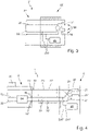
- FIG 3 shows a schematic sectional view of a charging cable 2 according to a further embodiment in the area of a vehicle-side plug 26 of the charging cable 2.
- the charging cable 2 corresponds in its structure essentially to that of FIG figure 2 .
- the charging cable 2 includes, among other things, a line 20 for energy transmission, for example with 230 V alternating current.
- the line 20 ends in the connector 26 on the vehicle side in a conductor contact 21.
- the temperature of the conductor contact 21 is monitored by a temperature sensor 24 assigned to it.
- the temperature sensor 24 has an assigned pair of lines 22 for signal transmission, in other words "signal lines" 22, which run in the cable harness 27 to the plug 26 on the charging station side and can be contacted there by the charging station in order to pick up the signals from the sensor 24.
- the sensor system described formed from the signal lines 22 and the temperature sensor 24, can be present multiple times, preferably if a plurality of lines for energy transmission, in particular formed as power lines (including the lines “L”, “L2” and/or “L3” for alternating current, or the "DC+” and/or “DC-” lines for direct current), as exemplified below with regard to FIG figure 4 described with reference to reference numeral 22'.
- a memory module 25 in the form of an EEPROM is also arranged in plug 26, which is communicatively connected to the two signal lines 22 of sensor 24 via two communication connections 250 or connecting lines, in order to enable communication via connected lines 22 in addition to the signal transmission of the signals from sensor 24 between the storage unit 25 and the charging station 3 to allow.
- the charging station 3 can read out data located in the memory module 25 via the lines 22 .
- the communication connections 250 can also be provided to supply energy to the memory module, preferably a memory provided therein and/or a microprocessor provided therein.
- the memory chip 25 can also be installed partially or completely in the plug 26 on the charging station side (see figure 2 ) - if present - and/or partially or fully arranged in the cable harness 27, preferably at the charging end of the charging cable 2.
- the memory chip 25 can also be communicatively connected to other lines 20, 22 of the charging cable 2, as described above in the general part (such as the PE conductor, PP conductor, or CP conductor).
- the memory chip 25 can alternatively comprise a computing unit in addition to a storage medium, preferably a microcontroller, preferably with an integrated storage medium, preferably a 1-wire memory chip.
- the memory chip 25 is preferably also supplied with power via the lines 22 communicatively connected to it.
- the memory module 25 can be connected to other lines 20, 22 already present in the charging cable 2, which are primarily assigned to a different purpose or a different function, for the power supply.
- At least one of the lines 22 connected to the memory module 25 for signal transmission can optionally be in the form of a data bus line, preferably as a standard bus, proprietary bus or 1-wire bus.
- the signal lines 22 used for the sensors in the cable harness 27 are preferably used for contacting the memory module 25 .
- figure 4 shows a schematic sectional view through a charging system 1 for charging a traction battery of an electric vehicle 4 according to a further embodiment.
- a charging station 3 is connected to the charging cable 2 via a charging cable connection 30, which in the present case is only indicated via contacts 31, 32 designed as connection terminals.
- the charging station 3 comprises conductor contacts 31 connected to a power grid (not shown) for the energy supply, which are connected to the lines 20 for the energy transmission of the charging cable 2 . Furthermore, the charging station 3 includes signal contacts 32, 32', which are connected to corresponding lines 22, 22' for signal transmission of the charging cable 2.
- the data transmission path of the memory module 25 (comprising a signal line 22 of the first pair and a signal line 22' of the second pair) differs accordingly pair) of the data transmission paths of the sensors 24, which each communicate via their pair of signal lines 22 and 22'.
- the charging station 3 can have the separate lines shown here for further communication of the sensor signals, present in the form of a sensor bus 36, and for further communication of the data read from the memory module 25, present in the form of a communication bus 35, with the logic circuit 34 Buses 35, 36 switched communicatively depending on the operating mode.
- the charging station 3 also includes a computing device 33 for calculating losses occurring during the energy transfer to the traction battery in the charging cable 2 connected to the charging cable connection 30 using cable-specific data of the charging cable 2.
- the charging station 3 can read the data from the storage unit 25 and use it to determine the expected energy losses in the charging cable 2 while charging the traction battery.
- the computing device 33 is designed to calculate the power loss in the charging cable 2 using the cable resistance determined from the cable-specific data and the measured current values, and also the calculated losses from the charging cable 2 for the correct calculation of the electrical energy delivered at the charging plug 26 from the via deduct the energy measured by the energy meter 6 .
- the computing device 33 communicates via a data connection 7 with a further functional unit 8 of the charging station 3, which is present as a controller for controlling the charging station 3, for example its state or mode, switching on and off the energy transmission for charging the vehicle battery, and /or to control the computing device 33 and/or the energy meter 6.
- the further functional unit 8 can be connected to the sensors 24 via the sensor bus 36 .
Landscapes
- Engineering & Computer Science (AREA)
- Power Engineering (AREA)
- Transportation (AREA)
- Mechanical Engineering (AREA)
- Electric Propulsion And Braking For Vehicles (AREA)
- Charge And Discharge Circuits For Batteries Or The Like (AREA)
Applications Claiming Priority (1)
| Application Number | Priority Date | Filing Date | Title |
|---|---|---|---|
| DE102021112750.5A DE102021112750A1 (de) | 2021-05-17 | 2021-05-17 | Ladekabel, Ladestation Ladesystem und Verfahren zum Laden einer Traktionsbatterie eines Elektrofahrzeuges |
Publications (1)
| Publication Number | Publication Date |
|---|---|
| EP4091866A1 true EP4091866A1 (fr) | 2022-11-23 |
Family
ID=81846369
Family Applications (1)
| Application Number | Title | Priority Date | Filing Date |
|---|---|---|---|
| EP22173802.4A Withdrawn EP4091866A1 (fr) | 2021-05-17 | 2022-05-17 | Câble de charge, station de charge, système de charge et procédé de charge d'une batterie de traction d'un véhicule électrique |
Country Status (2)
| Country | Link |
|---|---|
| EP (1) | EP4091866A1 (fr) |
| DE (1) | DE102021112750A1 (fr) |
Cited By (1)
| Publication number | Priority date | Publication date | Assignee | Title |
|---|---|---|---|---|
| WO2026061646A1 (fr) * | 2024-09-23 | 2026-03-26 | Liebherr-Mining Equipment Colmar Sas | Système d'alimentation électrique fixe pour un véhicule pouvant être entraîné électriquement |
Families Citing this family (1)
| Publication number | Priority date | Publication date | Assignee | Title |
|---|---|---|---|---|
| LU503454B1 (de) * | 2023-02-09 | 2024-08-09 | Phoenix Contact E Mobility Gmbh | Messgerät und Ladesystem zur eichrechtskonformen Messung von elektrischer Energie sowie Verfahren dazu |
Citations (5)
| Publication number | Priority date | Publication date | Assignee | Title |
|---|---|---|---|---|
| WO2014006096A2 (fr) * | 2012-07-04 | 2014-01-09 | Ebee Smart Technologies Gmbh | Câble de charge et procédé de détection d'un câble de charge |
| DE102018201698A1 (de) | 2018-02-05 | 2019-08-08 | Audi Ag | Verfahren zum Betreiben eines Ladekabels, Verfahren zum Betreiben einer Ladeinfrastruktur sowie Ladekabel |
| US20200180460A1 (en) * | 2018-12-07 | 2020-06-11 | Ohmenergy Limited | System and method for selectively charging an electric vehicle |
| US20200231063A1 (en) | 2019-01-17 | 2020-07-23 | Honda Motor Co.,Ltd. | Cable, power transfer managing system, managing apparatus, and computer-readable storage medium |
| KR102193414B1 (ko) * | 2020-03-20 | 2020-12-22 | 중앙제어 주식회사 | 전기차용 전력량 측정방법 및 장치 |
Family Cites Families (4)
| Publication number | Priority date | Publication date | Assignee | Title |
|---|---|---|---|---|
| DE102016214050B4 (de) | 2016-07-29 | 2024-05-08 | Audi Ag | Anordnung aus einem Kraftfahrzeug und einem Verbindungsmittel, Kraftfahrzeug und Verbindungsmittel |
| DE102017209450A1 (de) | 2017-06-02 | 2018-12-06 | Bayerische Motoren Werke Aktiengesellschaft | Verfahren zur Ermittlung der Temperatur einer Lade-Schnittstelle eines Fahrzeugs |
| DE102019200870A1 (de) | 2019-01-24 | 2020-07-30 | Audi Ag | Ladekabel |
| DE102019129799B4 (de) | 2019-11-05 | 2026-01-08 | Lisa Dräxlmaier GmbH | Verfahren und vorrichtung zum laden eines elektrisch angetriebenen fahrzeugs |
-
2021
- 2021-05-17 DE DE102021112750.5A patent/DE102021112750A1/de not_active Withdrawn
-
2022
- 2022-05-17 EP EP22173802.4A patent/EP4091866A1/fr not_active Withdrawn
Patent Citations (5)
| Publication number | Priority date | Publication date | Assignee | Title |
|---|---|---|---|---|
| WO2014006096A2 (fr) * | 2012-07-04 | 2014-01-09 | Ebee Smart Technologies Gmbh | Câble de charge et procédé de détection d'un câble de charge |
| DE102018201698A1 (de) | 2018-02-05 | 2019-08-08 | Audi Ag | Verfahren zum Betreiben eines Ladekabels, Verfahren zum Betreiben einer Ladeinfrastruktur sowie Ladekabel |
| US20200180460A1 (en) * | 2018-12-07 | 2020-06-11 | Ohmenergy Limited | System and method for selectively charging an electric vehicle |
| US20200231063A1 (en) | 2019-01-17 | 2020-07-23 | Honda Motor Co.,Ltd. | Cable, power transfer managing system, managing apparatus, and computer-readable storage medium |
| KR102193414B1 (ko) * | 2020-03-20 | 2020-12-22 | 중앙제어 주식회사 | 전기차용 전력량 측정방법 및 장치 |
Cited By (1)
| Publication number | Priority date | Publication date | Assignee | Title |
|---|---|---|---|---|
| WO2026061646A1 (fr) * | 2024-09-23 | 2026-03-26 | Liebherr-Mining Equipment Colmar Sas | Système d'alimentation électrique fixe pour un véhicule pouvant être entraîné électriquement |
Also Published As
| Publication number | Publication date |
|---|---|
| DE102021112750A1 (de) | 2022-11-17 |
Similar Documents
| Publication | Publication Date | Title |
|---|---|---|
| DE102021203363B4 (de) | Ladekabel, Anschlussvorrichtung zur Verwendung als erste Anschlussvorrichtung in einem Ladekabel und Anschlussvorrichtung zur Verwendung als zweite Anschlussvorrichtung in einem Ladekabel | |
| EP3688858B1 (fr) | Dispositif modulaire de chargement décalé des véhicules électriques à une station de charge | |
| DE102016214050B4 (de) | Anordnung aus einem Kraftfahrzeug und einem Verbindungsmittel, Kraftfahrzeug und Verbindungsmittel | |
| EP2699446B1 (fr) | Dispositif de charge pour véhicule | |
| EP2445745B1 (fr) | Determination de quantité d'énergie recu | |
| DE102011089567A1 (de) | System und Verfahren zum Evaluieren von Fahrzeugladeschaltkreisen | |
| DE102013007330A1 (de) | Wechselstecker zum länderübergreifenden elektrischen Laden eines Fortbewegungsmittels | |
| EP3572272A1 (fr) | Installation de charge, procédé de charge et système de charge | |
| LU500995B1 (de) | Vorrichtung und verfahren zum steuern der ladeleistung beim laden einer zu ladenden vorrichtung unter verwendung eines intelligenten ladekabels | |
| EP4091866A1 (fr) | Câble de charge, station de charge, système de charge et procédé de charge d'une batterie de traction d'un véhicule électrique | |
| EP3798045A1 (fr) | Ajustement d'une performance de charge | |
| DE102020108744A1 (de) | Dynamisch veränderliches Energieverteilsystem bestehend aus einer Anzahl von Elektrofahrzeugen, die temporär als Stromanbieter oder Stromabnehmer im Energieverteilsystem vorhanden sind | |
| DE102018208357B4 (de) | Adapter für das elektrische Laden eines Akkumulators eines Gerätes und Ladesystem hierfür | |
| WO2019219647A1 (fr) | Procédé destiné à faire fonctionner un dispositif de charge et dispositif de charge destiné à charger un accumulateur d'énergie pour véhicules électriques | |
| WO2023275344A2 (fr) | Câble de charge, station de charge, système de charge et procédé de transmission d'un courant de charge d'une station de charge à une batterie de traction | |
| DE102017209718A1 (de) | Adaptervorrichtung für eine Ladeeinrichtung eines Kraftfahrzeugs sowie Verfahren zum Betreiben der Adaptervorrichtung | |
| EP3670246A1 (fr) | Dispositif de charge pour chariots de manutention | |
| EP4173879A1 (fr) | Câble de charge et son procédé de fonctionnement | |
| DE102013113437A1 (de) | Verfahren zum Kalibrieren eines elektrisch angetriebenen Fahrzeugs auf einen Netzstandard | |
| DE102021214174B4 (de) | Vorrichtung und verfahren zum steuern der ladeleistung beim laden einer zu ladenden vorrichtung unter verwendung eines intelligenten ladekabels | |
| DE102019004206A1 (de) | Ladesystem fur ein elektrisch betreibbares Fahrzeug | |
| WO2019120684A1 (fr) | Appareil de commande pour un dispositif de charge et procédé de commande dudit dispositif de charge | |
| EP1734633B1 (fr) | Câble capable du transmission de données et de puissance pour la connexion d'une batterie avec un chargeur | |
| EP4372391B1 (fr) | Prise de mesure et réseau d'appareils d'installation électriques/électroniques | |
| DE102004006851B4 (de) | Schaltschrank- oder Rackanordnung |
Legal Events
| Date | Code | Title | Description |
|---|---|---|---|
| PUAI | Public reference made under article 153(3) epc to a published international application that has entered the european phase |
Free format text: ORIGINAL CODE: 0009012 |
|
| STAA | Information on the status of an ep patent application or granted ep patent |
Free format text: STATUS: THE APPLICATION HAS BEEN PUBLISHED |
|
| AK | Designated contracting states |
Kind code of ref document: A1 Designated state(s): AL AT BE BG CH CY CZ DE DK EE ES FI FR GB GR HR HU IE IS IT LI LT LU LV MC MK MT NL NO PL PT RO RS SE SI SK SM TR |
|
| STAA | Information on the status of an ep patent application or granted ep patent |
Free format text: STATUS: REQUEST FOR EXAMINATION WAS MADE |
|
| 17P | Request for examination filed |
Effective date: 20230210 |
|
| RBV | Designated contracting states (corrected) |
Designated state(s): AL AT BE BG CH CY CZ DE DK EE ES FI FR GB GR HR HU IE IS IT LI LT LU LV MC MK MT NL NO PL PT RO RS SE SI SK SM TR |
|
| STAA | Information on the status of an ep patent application or granted ep patent |
Free format text: STATUS: THE APPLICATION IS DEEMED TO BE WITHDRAWN |
|
| 18D | Application deemed to be withdrawn |
Effective date: 20251202 |