EP4091869A1 - Procédé et agencement de commande destinés à la charge/décharge d'un système de batterie haute tension - Google Patents
Procédé et agencement de commande destinés à la charge/décharge d'un système de batterie haute tension Download PDFInfo
- Publication number
- EP4091869A1 EP4091869A1 EP22167783.4A EP22167783A EP4091869A1 EP 4091869 A1 EP4091869 A1 EP 4091869A1 EP 22167783 A EP22167783 A EP 22167783A EP 4091869 A1 EP4091869 A1 EP 4091869A1
- Authority
- EP
- European Patent Office
- Prior art keywords
- soc
- target
- battery
- capacity
- window
- Prior art date
- Legal status (The legal status is an assumption and is not a legal conclusion. Google has not performed a legal analysis and makes no representation as to the accuracy of the status listed.)
- Granted
Links
Images



Classifications
-
- B—PERFORMING OPERATIONS; TRANSPORTING
- B60—VEHICLES IN GENERAL
- B60L—PROPULSION OF ELECTRICALLY-PROPELLED VEHICLES; SUPPLYING ELECTRIC POWER FOR AUXILIARY EQUIPMENT OF ELECTRICALLY-PROPELLED VEHICLES; ELECTRODYNAMIC BRAKE SYSTEMS FOR VEHICLES IN GENERAL; MAGNETIC SUSPENSION OR LEVITATION FOR VEHICLES; MONITORING OPERATING VARIABLES OF ELECTRICALLY-PROPELLED VEHICLES; ELECTRIC SAFETY DEVICES FOR ELECTRICALLY-PROPELLED VEHICLES
- B60L58/00—Methods or circuit arrangements for monitoring or controlling batteries or fuel cells, specially adapted for electric vehicles
- B60L58/10—Methods or circuit arrangements for monitoring or controlling batteries or fuel cells, specially adapted for electric vehicles for monitoring or controlling batteries
- B60L58/12—Methods or circuit arrangements for monitoring or controlling batteries or fuel cells, specially adapted for electric vehicles for monitoring or controlling batteries responding to state of charge [SoC]
- B60L58/13—Maintaining the SoC within a determined range
-
- B—PERFORMING OPERATIONS; TRANSPORTING
- B60—VEHICLES IN GENERAL
- B60L—PROPULSION OF ELECTRICALLY-PROPELLED VEHICLES; SUPPLYING ELECTRIC POWER FOR AUXILIARY EQUIPMENT OF ELECTRICALLY-PROPELLED VEHICLES; ELECTRODYNAMIC BRAKE SYSTEMS FOR VEHICLES IN GENERAL; MAGNETIC SUSPENSION OR LEVITATION FOR VEHICLES; MONITORING OPERATING VARIABLES OF ELECTRICALLY-PROPELLED VEHICLES; ELECTRIC SAFETY DEVICES FOR ELECTRICALLY-PROPELLED VEHICLES
- B60L58/00—Methods or circuit arrangements for monitoring or controlling batteries or fuel cells, specially adapted for electric vehicles
- B60L58/10—Methods or circuit arrangements for monitoring or controlling batteries or fuel cells, specially adapted for electric vehicles for monitoring or controlling batteries
- B60L58/16—Methods or circuit arrangements for monitoring or controlling batteries or fuel cells, specially adapted for electric vehicles for monitoring or controlling batteries responding to battery ageing, e.g. to the number of charging cycles or the state of health [SoH]
-
- B—PERFORMING OPERATIONS; TRANSPORTING
- B60—VEHICLES IN GENERAL
- B60L—PROPULSION OF ELECTRICALLY-PROPELLED VEHICLES; SUPPLYING ELECTRIC POWER FOR AUXILIARY EQUIPMENT OF ELECTRICALLY-PROPELLED VEHICLES; ELECTRODYNAMIC BRAKE SYSTEMS FOR VEHICLES IN GENERAL; MAGNETIC SUSPENSION OR LEVITATION FOR VEHICLES; MONITORING OPERATING VARIABLES OF ELECTRICALLY-PROPELLED VEHICLES; ELECTRIC SAFETY DEVICES FOR ELECTRICALLY-PROPELLED VEHICLES
- B60L2240/00—Control parameters of input or output; Target parameters
- B60L2240/10—Vehicle control parameters
- B60L2240/34—Cabin temperature
-
- B—PERFORMING OPERATIONS; TRANSPORTING
- B60—VEHICLES IN GENERAL
- B60L—PROPULSION OF ELECTRICALLY-PROPELLED VEHICLES; SUPPLYING ELECTRIC POWER FOR AUXILIARY EQUIPMENT OF ELECTRICALLY-PROPELLED VEHICLES; ELECTRODYNAMIC BRAKE SYSTEMS FOR VEHICLES IN GENERAL; MAGNETIC SUSPENSION OR LEVITATION FOR VEHICLES; MONITORING OPERATING VARIABLES OF ELECTRICALLY-PROPELLED VEHICLES; ELECTRIC SAFETY DEVICES FOR ELECTRICALLY-PROPELLED VEHICLES
- B60L2240/00—Control parameters of input or output; Target parameters
- B60L2240/60—Navigation input
- B60L2240/64—Road conditions
- B60L2240/642—Slope of road
-
- B—PERFORMING OPERATIONS; TRANSPORTING
- B60—VEHICLES IN GENERAL
- B60L—PROPULSION OF ELECTRICALLY-PROPELLED VEHICLES; SUPPLYING ELECTRIC POWER FOR AUXILIARY EQUIPMENT OF ELECTRICALLY-PROPELLED VEHICLES; ELECTRODYNAMIC BRAKE SYSTEMS FOR VEHICLES IN GENERAL; MAGNETIC SUSPENSION OR LEVITATION FOR VEHICLES; MONITORING OPERATING VARIABLES OF ELECTRICALLY-PROPELLED VEHICLES; ELECTRIC SAFETY DEVICES FOR ELECTRICALLY-PROPELLED VEHICLES
- B60L2240/00—Control parameters of input or output; Target parameters
- B60L2240/60—Navigation input
- B60L2240/66—Ambient conditions
- B60L2240/662—Temperature
-
- B—PERFORMING OPERATIONS; TRANSPORTING
- B60—VEHICLES IN GENERAL
- B60L—PROPULSION OF ELECTRICALLY-PROPELLED VEHICLES; SUPPLYING ELECTRIC POWER FOR AUXILIARY EQUIPMENT OF ELECTRICALLY-PROPELLED VEHICLES; ELECTRODYNAMIC BRAKE SYSTEMS FOR VEHICLES IN GENERAL; MAGNETIC SUSPENSION OR LEVITATION FOR VEHICLES; MONITORING OPERATING VARIABLES OF ELECTRICALLY-PROPELLED VEHICLES; ELECTRIC SAFETY DEVICES FOR ELECTRICALLY-PROPELLED VEHICLES
- B60L2250/00—Driver interactions
- B60L2250/18—Driver interactions by enquiring driving style
-
- B—PERFORMING OPERATIONS; TRANSPORTING
- B60—VEHICLES IN GENERAL
- B60L—PROPULSION OF ELECTRICALLY-PROPELLED VEHICLES; SUPPLYING ELECTRIC POWER FOR AUXILIARY EQUIPMENT OF ELECTRICALLY-PROPELLED VEHICLES; ELECTRODYNAMIC BRAKE SYSTEMS FOR VEHICLES IN GENERAL; MAGNETIC SUSPENSION OR LEVITATION FOR VEHICLES; MONITORING OPERATING VARIABLES OF ELECTRICALLY-PROPELLED VEHICLES; ELECTRIC SAFETY DEVICES FOR ELECTRICALLY-PROPELLED VEHICLES
- B60L2260/00—Operating Modes
- B60L2260/40—Control modes
- B60L2260/50—Control modes by future state prediction
- B60L2260/52—Control modes by future state prediction drive range estimation, e.g. of estimation of available travel distance
-
- B—PERFORMING OPERATIONS; TRANSPORTING
- B60—VEHICLES IN GENERAL
- B60L—PROPULSION OF ELECTRICALLY-PROPELLED VEHICLES; SUPPLYING ELECTRIC POWER FOR AUXILIARY EQUIPMENT OF ELECTRICALLY-PROPELLED VEHICLES; ELECTRODYNAMIC BRAKE SYSTEMS FOR VEHICLES IN GENERAL; MAGNETIC SUSPENSION OR LEVITATION FOR VEHICLES; MONITORING OPERATING VARIABLES OF ELECTRICALLY-PROPELLED VEHICLES; ELECTRIC SAFETY DEVICES FOR ELECTRICALLY-PROPELLED VEHICLES
- B60L2260/00—Operating Modes
- B60L2260/40—Control modes
- B60L2260/50—Control modes by future state prediction
- B60L2260/54—Energy consumption estimation
Definitions
- the invention relates to a method for charging/discharging control of a high-voltage battery system according to the preamble of claim 1 and an arrangement for carrying out the method according to the preamble of claim 10.
- the invention is particularly useful in a purely battery-powered vehicle or a partially battery-powered vehicle, in particular applicable to a plug-in hybrid vehicle.
- High-voltage battery systems are used to store energy for many purposes, especially where off-grid operation is necessary or desired. Such energy stores can be found, for example, in cars, ships and airplanes, where they supply the energy required to start the engine. In recent years, their use as traction batteries for partially or fully electrically operated vehicles has gained in importance. Electrically operated small devices such as electric tools, smartphones and cameras are also supplied with energy by means of accumulators - i.e. rechargeable batteries. Furthermore, rechargeable energy storage devices of the type in question are becoming increasingly important as buffer storage devices in order to initially store wind or solar energy and feed it into the power grid at a later point in time.
- accumulators are used, which differ in particular in the materials used for energy storage.
- Lead-acid batteries for example, are commonly used as starter batteries for cars.
- Portable electrical or electronic devices usually have lithium-ion batteries.
- Lithium-based energy storage is usually also found in partially or fully electrically operated vehicles.
- the manufacturers therefore usually specify a permissible state of charge (SoC) range, within which the accumulator is to be operated in order to achieve a guaranteed number of cycles or a guaranteed calendar aging.
- SoC state of charge
- the permissible state of charge range varies depending on the type of accumulator. With lithium-ion accumulators, for example, the middle charge range between 10% and 80% is used, with lead accumulators the upper charge range between 60% and 100%.
- U.S. 8,970,173 B2 therefore a method for setting the operating mode of an electric vehicle proposed, wherein the operating mode is selected from a variety of operating modes.
- the plurality of operating modes includes at least one battery life mode and one default mode, wherein the battery life mode is configured with respect to the selection of operating and charging parameters such that battery health and battery life are emphasized over vehicle range and/or vehicle performance.
- the system includes a thermal management system for maintaining the vehicle's battery pack within one of multiple temperature ranges and a charging system for charging the vehicle's battery pack to one of multiple minimum and maximum SoC levels.
- SoC windows adapted to a number of predefined operating modes are therefore kept available and set by the driver actuating a selection device. Although such a choice creates greater flexibility in the use of a vehicle, it transfers the responsibility for the longest possible service life of the high-voltage battery to the driver.
- Another approach is in the EP 3 050 739 A1 suggested.
- the method described there provides that for the control and/or regulation of at least one operating parameter of the electrical energy store influencing the state of aging of an electrical energy store of a motor vehicle, an actual state of aging of the electrical energy store and a target state of aging are determined.
- the actual aging condition shows increased aging compared to the target aging condition or less aging. If the actual aging condition is higher than the desired aging condition, an operating parameter range is adjusted in such a way that the electrical energy store is operated within the adjusted operating parameter range with a reduced aging rate.
- the operating parameter range can be adjusted in such a way that the electrical energy storage device is operated within the adjusted operating parameter range with an increased aging rate.
- the adjusted operating parameter range can be the state of charge window (SoC window) of the energy store.
- the object of the invention is to provide a method in which the SoC window is defined dynamically in such a way that the charge actually required between two charging processes is available.
- the charge that is actually required is to be understood as meaning the charge that—possibly including a safety reserve—is necessary to accomplish a task to be performed using the stored charge.
- Another part of the task is to specify an arrangement for carrying out the method.
- the starting point is an implemented charge/discharge control of a high-voltage battery system, which allows different charge state ranges to be set by introducing correspondingly narrowed SoC windows in order to optimize the aging of the battery.
- Optimizing the aging state of the battery means here that the SoC window is smaller than a maximum permissible SoC window (SoC-F max) in a large number of cases and is within the maximum permissible SoC window (SoC-F max) .
- the SoC window is set using the charge/discharge control and the battery is charged within the range specified by the SoC window.
- the charge/discharge controller controls the discharging of the battery in such a way that the state of charge remains within the state of charge range specified by the SoC window.
- the advantage of the method is that the lower value of the SoC window UG (SoC-F) and the upper value of the SoC window OG (SoC-F) dynamically, by predictive estimation of the capacity required between two charging processes, always Values are set that cover the battery capacity actually required.
- the lower value of the target SoC window is set larger than the minimum permissible lower value of the maximum permissible SoC Window and the upper value of the target SoC window is set smaller than the maximum permissible upper value of the maximum permissible SoC window. In these cases, the battery is therefore operated in a range that is favorable for aging.
- the actual aging of the battery is therefore always lower than the aging that occurs when the SoC window is set to the maximum permissible net capacity specified by the manufacturer.
- the method according to the invention automatically leads to an optimum in the aging of the battery, without the need for external intervention and without sacrificing comfort.
- the charge/discharge controller checks whether the SoC window for a specified number of charge-discharge cycles was less than the maximum allowable SoC window. If so, the charge/discharge controller sets a SoC window that is greater than the maximum allowable SoC window and less than or equal to a predefined extended SoC window. In exceptional cases, this procedure allows the battery to be charged to an extended net capacity that is greater than the maximum permissible net capacity specified by the manufacturer.
- the charging/discharging controller triggers a signal .
- the signaling can be of an optical, acoustic or haptic nature. This signals to an operator that a predefined task can only be completed with an intermediate charge.
- the at least one parameter determined in the process prior to charging which predicts the usable capacity of the battery required until the next charging, can be of different nature. It is thus possible to use a predefined task as a parameter. It can be provided, for example, to select a predefined task from a plurality of predefined tasks and to use the parameter assigned to it. Another possibility consists in predicting a task, in which case a plurality of parameters can be used to determine the task in order to obtain a parameter.
- a task is that a fully electrically operated vehicle is to cover a certain distance between a location "A" and a location "B”
- the distance to be covered and an associated height profile can be determined as parameters from the route determined using a route calculation system and from A first parameter can be formed from these parameters, which at least partially defines the task in terms of the energy required to complete it.
- Another parameter can be environmental conditions. For example, the ambient temperature, the season, the time of day or other environmental parameters from which a parameter can be formed, for example the traffic situation at a specific time of day, come into consideration as parameters for environmental conditions.
- a second parameter is formed from a temperature prevailing at a certain time of the year and a traffic situation prevailing at a certain time of day.
- a further parameter can be of a personal nature, namely when characteristics of an operator play a role in order to accomplish a task with regard to the energy required for it.
- an additional energy consumption or reduced energy consumption can be determined as a parameter from a person-related behavior analysis carried out in advance.
- "covering a certain distance" this means that, for example, a driving style analysis carried out in advance supplies an energy-consumption-specific parameter.
- each charging process can be controlled as a function of the outside temperatures and the resulting need for air conditioning, among other things, in such a way that the driver always has a reliable, fixed/constant range, in particular over the entire guaranteed property duration of the high-voltage traction battery, provided.
- the method according to the invention can be used particularly advantageously in connection with a high-voltage traction battery of a fully electrically or partially electrically operated vehicle.
- the predefined task is to cover a minimum route with a predefined altitude profile, with the length of the route (for example 50 km, 100 km, 150 km, etc.) as well as the altitude profile (for example "flat”, “mountainous”, “mountainous”) can be entered via appropriate input means.
- the input is converted into a parameter that defines the capacity of the battery required to complete the task, for example driving distance 100 km, elevation profile "flat".
- a route calculation system is advantageously used to determine the route.
- This advantageously uses data from a planning system, whereby the planning system can be an electronic appointment calendar, an electronic resource planner for a goods distribution system or similar facilities in which the locations to be visited, the sequence of the locations to be visited and/or the time of day which is planned to arrive at at least one location.
- the route calculation system can determine a driving route and determine the parameter from the determined driving route and the elevation profile assigned to the driving route, or an equivalent variable.
- the outside temperature is also important for the energy consumption of a fully or partially electrically operated vehicle. It is therefore advantageous to take the outside temperature from a memory in which a large number of outside temperatures are predefined according to the season and/or time of day and/or location. The respectively applicable outside temperature is taken from the memory with the aid of at least one date and/or time and/or location and forms a parameter.
- Another advantageous possibility of obtaining the outside temperature is to obtain outside temperatures defined in terms of time and/or location as forecast outside temperatures from a weather forecast system by means of, for example, radio data transmission.
- Temperatures and driving route are to be advantageously linked, for example in such a way that a plurality of forecast outside temperatures are determined in relation to location and/or time from a weather forecast system for a determined driving route and that the outside temperatures obtained in this way are linked to the driving route in relation to location and/or time and that the likely required capacity of the battery is determined from this linked data.
- the likely required capacity of the battery can be determined using the driving route as the first parameter, the predicted outside temperatures as the second parameter and the third driver-specific parameter.
- a tool, vehicle or system operated with a high-voltage battery system is used in essentially the same way, it may be sufficient to obtain the at least one parameter from the evaluation of at least one previous charge/discharge cycle.
- the battery can be charged to its net capacity.
- the capacity actually required is recorded and used as a parameter to determine the capacity required for the next use, and to derive a SoC window from this and charge the battery within the limits set by the SoC window for the next use.
- the invention also includes a charging/discharging arrangement for carrying out the method.
- the charging/discharging arrangement advantageously contains a number of components that are addressed below.
- the charging/discharging arrangement in question is an arrangement made up of mechanical and electronic components, as are commonly used today.
- Such charging/discharging arrangements are usually part of a computer-aided control system which uses processors to process control instructions stored in memories.
- the components addressed below and the control sequences they execute are those for command routines Combined control instructions which - processed by the processor or processors - execute the control tasks assigned to them by means of input or output means, sensors, actuators and transmission means that are operatively connected to this.
- the components addressed below are therefore normally not delimitable hardware units but only exist virtually and temporarily within the framework of a computer-aided control system.
- the charging/discharging arrangement contains a determination device which determines at least one characteristic, the characteristic predicting the usable capacity of the battery required until the next charging.
- the determination device can obtain data from subsystems with which it is temporarily connected, for example by radio, via a corresponding data exchange.
- a calculation device is provided which determines a required usable capacity or a variable equivalent thereto from the parameter or parameters. The way in which this is done can vary, so the parameters can serve to determine the required usable capacity from a characteristic curve or map, but it can also be necessary to carry out complex calculations, depending on the nature of the parameters.
- a determination device which uses the required usable capacity to determine a SoC window that optimizes the aging state of the battery; for this purpose, the determination device uses a simple assignment rule.
- a setting device is also provided, which sets the lower value of the SoC window and the upper value of the SoC window.
- the charging/discharging arrangement is designed such that it controls the charging process in such a way that the battery is charged up to the upper value of the SoC window and controls the discharging process during operation in such a way that the battery only reaches the lower value of the SoC window is discharged.
- the components mentioned above can be part of a global control system that takes over the control of the vehicle as a whole. It is particularly advantageous to design the charging/discharging arrangement as a module that can optionally be added to the control system.
- control instructions are control instructions combined into command routines which - processed by the processor or processors - carry out the control tasks assigned to them by means of input and output means, sensors, actuators and Execute means of transmission.
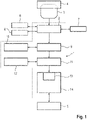
- the arrangement for charging/discharging control 1 contains a determination device 2. This is initiated by plugging a charging plug 3 into a charging station 4 to determine parameters.
- the parameters determined predict the usable capacity of a high-voltage battery system 5 required until the next charge, in other words, define the energy requirement that must be kept available in the battery 5 to complete a task until the next charge.
- the task to be completed is determined by the determining device 2 from an electronic appointment calendar 6 . It is also assumed that the places to be visited by the vehicle and the order in which these are to be approached, are stored in the electronic diary 6 for the determination device 2 to be identifiable.
- the appointment calendar entries indicate that at a given time "X”, starting from the current position at the charging station 4, three locations in the order location "A", location "B", location “C” and then the Charging station 4 are to be approached and the journey has ended at a point in time "Y".
- the charging station 4 can be a wall box at the vehicle's home location, for example.
- the determination device 2 transfers the task definition charging station 4 -> location "A"-> location "B"-> location "C”-> charging station 4 to a route calculation system 7, which can be part of a navigation system, not shown here, in order to determine a driving route.
- the route calculation system 7 determines a route from the data transmitted to it, which, in addition to the routing, which is not relevant in this context, determines the route S desired and the terrain profile (elevation profile) GP and transmits this information to the determination device 2 hands over.
- the determination device 2 determines a terrain profile type GP type from the terrain profile GP. It is assumed here that twenty different terrain profile types GP 1 to GP 20 are provided and the determination device 2 assigns the determined terrain profile GP to one of these terrain profile types GP 1 to GP 20 .
- the determination system 2 is wirelessly connected to a weather forecasting system 8 and determines time-related temperature data for the locations “charging station 4", location "A”, location "B”, location “C”, “charging station 4". from this an average temperature T v is calculated.
- the determination device 2 in the example shown here has determined the parameters “travel distance S target ”, “terrain profile type GP type ” and “predicted average temperature T v ”. This selection was made for reasons of better clarity; in fact, of course, any number of parameters can be determined with the necessary accuracy and used for the further determination of the required usable capacity of the battery 5, which is described as an example below.
- the determination device 2 transfers the determined parameters "travel distance S target ", "terrain profile type GP type " and "predicted average temperature T v ". to a calculation device 9, which determines the required usable capacity of the battery 5 from the parameters.
- the predicted average temperature T v is 20°C.
- the calculation device 9 is operatively connected to a first storage device 10 .
- the calculation device 9 uses the content of the first memory device 10. This contains a large number of characteristic diagrams, each in digital form. Each of these maps is valid for a specific temperature T s and indicates the required usable capacity K depending on the route S and terrain profile type GP type .
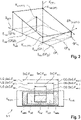
- the 2 shows a three-dimensional Cartesian coordinate system in which the dependency of the required capacity K on the route S and the terrain profile type GP type is shown in the form of a characteristic diagram.
- the characteristics map applies to a temperature T v of 20° C., that is to say the average temperature T v which the determination device 2 has determined.
- T v the average temperature
- the map is used within two limits of a minimum capacity K min (20° C.) and a maximum capacity K max (20° C.) .
- the minimum capacity K mm(20°C) is defined in such a way that an influence on the aging of the battery with capacities smaller than K mm(20°C) is insignificant and can be ignored.
- a minimum distance between S min (GP 1 ) and S min (GP 20 ) is available after each loading, depending on the type of terrain profile to be traveled, even if other parameters for calculating a required capacity were not determined.
- the other limitation of the usable range of the map is defined by a maximum permissible capacity K max(20°C) of the battery at 20°C. This is the maximum net capacity allowed for the battery at a temperature of 20°C. With this maximum permissible capacity K max (20° C.) , different maximum distances S max can be covered, depending on the type of terrain profile traveled, namely between S max (GP 20 ) and S max (GP 1 ).
- the task of the determination device 11 is to determine an SoC window from the required capacitance K target (20° C.) .
- the SoC window is a range within which a battery is charged.
- SoC windows and their relation to the capacity of a high-voltage battery system are shown in 3 illustrated.
- a battery 5.1 is shown there, and the form of a capacity diagram has been selected for the representation.
- the battery has a gross capacity K gross .
- K gross the gross capacity
- the manufacturer usually specifies a net capacity K net within which the battery is to be operated in order to achieve a guaranteed number of cycles, ie a guaranteed number of charge-discharge cycles. This means that the battery must not be charged up to its gross capacity K gross and must not be discharged below a specified capacity.
- So the usable range is within a window commonly referred to as the SoC window.
- this usable range is assumed to be the maximum usable SoC window SoC-F max in the sense of optimizing the aging of the battery.
- This maximum usable SoC window SoC-F max is assigned a first value as upper limit OG(SoC-F max ), up to which the battery may be charged, and a second value as lower limit UG(SoC-F max ), up to which the battery may be discharged.
- the resulting SoC window has the value OG(SoC-F min ) as the upper limit and the value UG(SoC-F min ) as the lower limit.
- the range between the net capacity K net and the minimum capacity K min represents the variably usable capacity range.
- the variable capacity range is understood here to mean that when the required capacity K is intended to handle a predictively determined task - here a route S target - is greater than the minimum capacity K min and smaller than the net capacity K net , from the required capacity K target a SoC window SoC-F target is derived, which has a first value as the upper limit OG(SoC -F should ) and a second value is assigned as the lower limit UG(SoC-F target ).
- the upper limit OG(SoC-F target ) is smaller than OG(SoC-F max ) and the lower limit UG(SoC-F target ) is greater than UG(SoC-F max ), so that the battery can be charged up to upper limits OG(SoC-F target ) and discharging the battery down to the lower limit UG(SoC-F target ) has a positive effect on battery aging.
- the task of the determination device 11 is to determine an SoC window from the required capacity K setpoint (20° C.) .
- the determination device 11 uses a second storage device 12.
- To determine the SoC window access to the contents of the storage device 12 is derived from the required capacity K setpoint (20° C.) , which contains the data from a large number of SoC windows in the form of values for their upper and lower limits.
- the determining device 11 uses the required capacitance K target (20° C.) - quasi as addressing - from the storage device 12 to take a first value as the upper limit OG(SoC-F target ) and a second value as the lower limit UG (SoC-F target ) of the SoC window SoC-F target and transmits this to a setting device 13 of a battery management system 14 that controls the charging/discharging process of the battery 5 .
- the battery management system 14 controls the charging process of the battery 5 in such a way that it is charged up to the upper limit OG(SoC-F target ) of the SoC window SoC-F target.
- the battery management system 14 controls the discharging process in such a way that the battery 5 is not discharged below the lower limit UG(SoC-F target ) of the SoC window SoC-F target.
- the battery management system 14 controls the discharging process in such a way that the battery 5 is not discharged below the lower limit UG(SoC-F target ) of the SoC window SoC-F target.
- part of the capacity range below the lower limit UG(SoC-F target ) of the required capacity K and above the lower limit UG(SoC-F max ) of the net -Capacity K net is released as a capacity reserve when requested by the driver.
- the method according to the invention is not limited to applications in the vehicle sector.
- Another application shows 4 in the form of a flow chart.
- the task to be completed is essentially always the same and is only subject to minor fluctuations. This is the case, for example, when using a software tool that is powered by a battery, the same work processes are always carried out during two charging processes, for example during a work shift on an assembly line. It is also assumed that the net capacity of the battery is designed in such a way that the software tool can safely handle the task to be performed with one charge and that a safety reserve normally remains in the battery.
- the charging/discharging control is part of the tool and the tool has a switching device with which a maximum charge can be requested.
- the representation in 3 referenced for the sake of illustration, reference is also made to the representation in 3 referenced. The above for 3 statements made are therefore also valid, for example 4 , with the exception of the remarks on the minimum capacity K min , which are shown in the example 4 is not provided.
- the method as shown in 4 contain the process steps listed below as examples. Steps to be carried out manually are indicated in the illustration by dashed lines.
- the process sequence described above ensures that a SoC window is used for the charging/discharging process of the battery, which is always within the maximum permissible SoC window SoC-F max , in the majority of cases well within, so that the Aging of the battery is favorably influenced and the achievable number of cycles is increased.
- the "maximum charge" switching device can also be set manually, in that the operator actuates an input means. This is necessary, for example, when the tool that works according to the method described above is new or used at a different location.
- a tool equipped according to the above-described features automatically searches for a target capacity K setpoint based on the previous work cycle in the manner of a self-learning process.
- the connected SoC window SoC-F target is in most cases smaller than the SoC window SoC-F net assigned to the net capacity K net and lies within the limits of the SoC window SoC- assigned to the net capacity K net F net , so that an optimized aging of the battery is achieved.
- the method described above can in principle also be used for a vehicle application if the route to be covered between two charging processes is essentially the same. It is therefore conceivable to use vehicles in a mail or parcel delivery service in such a way that the route is essentially always the same. In this case, the procedure can be 4 transferred to this application.
- a core idea of the invention is that each charging process of the battery 5 is controlled depending on the outside temperatures and the resulting need for air conditioning in such a way that the driver is always provided with a reliable fixed/constant range, in particular over the guaranteed property duration of the battery.
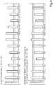
- the customer can be provided with a fixed/constant range of 200 km, as can be seen from the two diagrams in the figure 5 emerges.
- the upper diagram illustrates an electrical energy requirement per 100 km in kWh over the months of a year.
- the diagram below illustrates the corresponding, required HV battery energy content for each month, with which a constant range of, for example, 200 km in kWh is made possible.
- the above facts are based on the Figures 6 to 9 explained again:
- the vehicle has a battery 5 with a gross energy content of 80 kWh.
- the outside temperature is 18°C.
- a classic driving cycle for delivery services is planned as an example.
- the electrical consumption for this specific cycle is estimated at the current outside temperature.
- the battery content required for this (e.g. 50 kWh) to provide the constant range (i.e. e.g. 200 km) is calculated and transmitted to an intelligent charger, for example.
- the battery 5 is charged via the charger, for example up to an energy content of 50 kWh.
- a trip to work for example, is planned.
- the electrical consumption per 100 km i.e. drive + HV auxiliary consumers
- the driver selects the pre-conditioning of the vehicle interior to 22°C the evening before, for example via his mobile phone, which results in a reduced power requirement for the HV heater in the interior.
- the driver can specify that he can recharge his vehicle at work.
- the evaluation unit can determine the required HV battery charge (plus inaccuracy allowance). For example, a battery with a gross energy content of 80 kWh and an energy requirement per 100 km of approx. 20 kWh, the energy content charged via the charger is 60%, for example.
- the outside temperature can be around 15°C.
- a trip to the hardware store with a trailer is planned.
- the required range to hardware stores can be determined in the immediate vicinity using the navigation device or by accessing private calendars/entry into vehicle apps.
- the electrical energy requirement per 100 km (drive + HV auxiliary consumers) from previously evaluated trips with a trailer and with similar outside temperatures is taken into account.
- the maximum payload of the trailer is taken into account.
- the evaluation unit can determine the required battery charge (plus inaccuracy allowance).
- a battery with a gross energy content of 80 kWh results in an energy requirement of approx. 35 kWh per 100 km. Due to the higher (predicted) consumption, a higher amount of energy is loaded into the battery, for example 70 kWh.
Landscapes
- Engineering & Computer Science (AREA)
- Life Sciences & Earth Sciences (AREA)
- Sustainable Development (AREA)
- Sustainable Energy (AREA)
- Power Engineering (AREA)
- Transportation (AREA)
- Mechanical Engineering (AREA)
- Secondary Cells (AREA)
Applications Claiming Priority (1)
| Application Number | Priority Date | Filing Date | Title |
|---|---|---|---|
| DE102021205058.1A DE102021205058A1 (de) | 2021-05-18 | 2021-05-18 | Verfahren und Anordnung zur Lade-/Entladesteuerung eines Hochvolt-Batteriesystems |
Publications (2)
| Publication Number | Publication Date |
|---|---|
| EP4091869A1 true EP4091869A1 (fr) | 2022-11-23 |
| EP4091869B1 EP4091869B1 (fr) | 2025-06-11 |
Family
ID=81307402
Family Applications (1)
| Application Number | Title | Priority Date | Filing Date |
|---|---|---|---|
| EP22167783.4A Active EP4091869B1 (fr) | 2021-05-18 | 2022-04-12 | Procédé et agencement de commande destinés à la charge/décharge d'un système de batterie haute tension |
Country Status (2)
| Country | Link |
|---|---|
| EP (1) | EP4091869B1 (fr) |
| DE (1) | DE102021205058A1 (fr) |
Cited By (1)
| Publication number | Priority date | Publication date | Assignee | Title |
|---|---|---|---|---|
| CN116859263A (zh) * | 2023-06-28 | 2023-10-10 | 中国第一汽车股份有限公司 | 动力电池的健康状态估计方法、装置及车辆 |
Families Citing this family (2)
| Publication number | Priority date | Publication date | Assignee | Title |
|---|---|---|---|---|
| DE102024201277A1 (de) * | 2024-02-13 | 2025-08-14 | Robert Bosch Gesellschaft mit beschränkter Haftung | Verfahren und Vorrichtung zur Generierung von nutzerindividuellen Ladestrategien für Gerätebatterien von technischen Geräten |
| DE102024208902A1 (de) * | 2024-09-18 | 2026-03-19 | Volkswagen Aktiengesellschaft | Verfahren zum Laden einer Batterie eines Elektrofahrzeugs an einer Elektroladestation, Vorrichtung zur Datenverarbeitung, Computerprogrammprodukt und Elektrofahrzeug |
Citations (7)
| Publication number | Priority date | Publication date | Assignee | Title |
|---|---|---|---|---|
| US20110202217A1 (en) * | 2010-02-18 | 2011-08-18 | University Of Delaware | Electric vehicle equipment for grid-integrated vehicles |
| EP2502774A1 (fr) * | 2009-11-17 | 2012-09-26 | Toyota Jidosha Kabushiki Kaisha | Véhicule et procédé de commande du véhicule |
| WO2013055830A1 (fr) * | 2011-10-10 | 2013-04-18 | Proterra Inc. | Systèmes et procédés de maximisation de durée de vie de batterie dans des applications à itinéraires fixes |
| EP2662949A1 (fr) * | 2011-01-06 | 2013-11-13 | Nec Corporation | Dispositif de commande de charge, procédé de commande de charge, et programme associé |
| US8970173B2 (en) | 2012-02-28 | 2015-03-03 | Tesla Motors, Inc. | Electric vehicle battery lifetime optimization operational mode |
| EP3050739A1 (fr) | 2015-01-29 | 2016-08-03 | MAN Truck & Bus AG | Procede et dispositif de commande et/ou de reglage d'au moins un parametre de fonctionnement influençant un etat de vieillissement d'un systeme de stockage energetique electrique |
| US20200108726A1 (en) * | 2018-10-03 | 2020-04-09 | Ford Global Technologies, Llc | Variable charging strategy for plugin electric vehicles |
Family Cites Families (1)
| Publication number | Priority date | Publication date | Assignee | Title |
|---|---|---|---|---|
| DE102018201045A1 (de) | 2018-01-24 | 2019-07-25 | Robert Bosch Gmbh | Verfahren zum Laden wenigstens einer Batterie eines Elektrofahrzeuges |
-
2021
- 2021-05-18 DE DE102021205058.1A patent/DE102021205058A1/de not_active Withdrawn
-
2022
- 2022-04-12 EP EP22167783.4A patent/EP4091869B1/fr active Active
Patent Citations (7)
| Publication number | Priority date | Publication date | Assignee | Title |
|---|---|---|---|---|
| EP2502774A1 (fr) * | 2009-11-17 | 2012-09-26 | Toyota Jidosha Kabushiki Kaisha | Véhicule et procédé de commande du véhicule |
| US20110202217A1 (en) * | 2010-02-18 | 2011-08-18 | University Of Delaware | Electric vehicle equipment for grid-integrated vehicles |
| EP2662949A1 (fr) * | 2011-01-06 | 2013-11-13 | Nec Corporation | Dispositif de commande de charge, procédé de commande de charge, et programme associé |
| WO2013055830A1 (fr) * | 2011-10-10 | 2013-04-18 | Proterra Inc. | Systèmes et procédés de maximisation de durée de vie de batterie dans des applications à itinéraires fixes |
| US8970173B2 (en) | 2012-02-28 | 2015-03-03 | Tesla Motors, Inc. | Electric vehicle battery lifetime optimization operational mode |
| EP3050739A1 (fr) | 2015-01-29 | 2016-08-03 | MAN Truck & Bus AG | Procede et dispositif de commande et/ou de reglage d'au moins un parametre de fonctionnement influençant un etat de vieillissement d'un systeme de stockage energetique electrique |
| US20200108726A1 (en) * | 2018-10-03 | 2020-04-09 | Ford Global Technologies, Llc | Variable charging strategy for plugin electric vehicles |
Cited By (1)
| Publication number | Priority date | Publication date | Assignee | Title |
|---|---|---|---|---|
| CN116859263A (zh) * | 2023-06-28 | 2023-10-10 | 中国第一汽车股份有限公司 | 动力电池的健康状态估计方法、装置及车辆 |
Also Published As
| Publication number | Publication date |
|---|---|
| EP4091869B1 (fr) | 2025-06-11 |
| DE102021205058A1 (de) | 2022-11-24 |
Similar Documents
| Publication | Publication Date | Title |
|---|---|---|
| EP4091869B1 (fr) | Procédé et agencement de commande destinés à la charge/décharge d'un système de batterie haute tension | |
| DE102015120581B4 (de) | Verfahren und ein Fahrzeugsystem zur musterbasierten Ladeplanung | |
| DE102019101182A1 (de) | Intelligent ladende batteriesysteme und verfahren für elektrifizierte fahrzeuge | |
| DE102016119972A1 (de) | Steuerstrategie zum Aufladen eines elektrisch betriebenen Fahrzeugs über mehrere Stationen einer Fahrroute | |
| DE102018116826A1 (de) | Fahrzeug mit modellbasierter streckenenergievorhersage, -korrektur und -optimierung | |
| DE102018209997A1 (de) | Verfahren zum Ermitteln einer Richtgeschwindigkeit für ein elektrisch betriebenes Fahrzeug | |
| DE112009004957T5 (de) | Batteriesystem und Fahrzeug, das mit einem Batteriesystem ausgestattet ist | |
| WO2020074554A1 (fr) | Procédé et dispositif backend de commande de charge prédictive pour un accumulateur d'énergie électrique d'un véhicule automobile | |
| DE102009048821A1 (de) | Verfahren zur Reichweitenermittlung für Fahrzeuge, insbesondere Elektrofahrzeuge | |
| DE102010003762A1 (de) | Verfahren sowie Einrichtung für ein Reichweitenmanagement eines Fahrzeugs mit elektromotorischem Antrieb | |
| EP2697608A2 (fr) | Procédé et dispositif pour effectuer un calcul d'itinéraire pour un véhicule | |
| DE102013216090A1 (de) | Ein Fahrzeug unter erneuerbarer Energie betreibendes Managementsystem | |
| DE102012213452A1 (de) | System und verfahren zum aufladen einer batterie | |
| WO2013182382A2 (fr) | Procédé pour commander le mode de charge dans un véhicule automobile électrique | |
| DE112016006192T5 (de) | Fahrzeug-Klimaanlage | |
| DE102011112382A1 (de) | Verfahren zum Regeln der Energiezufuhr für den Antrieb eines Fahrzeugs | |
| DE102013008716A1 (de) | Fahrzeug mit einem elektrischen Antrieb sowie Verfahren zum Betreiben eines solchen Fahrzeugs | |
| DE102022212186A1 (de) | Verfahren zur Vorhersage von erwarteten Lastprofilen zur Steuerung der Ladeleistung einer Batterie | |
| DE102021001290A1 (de) | Verfahren zum Betreiben einer Batterie | |
| DE102013201563A1 (de) | Personalisierung der Energieversorgung und des Energiemanagements in Fahrzeugen | |
| DE102020115896B4 (de) | Verfahren und Assistenzsystem für ein Wärmemanagement in einem Kraftfahrzeug und Kraftfahrzeug | |
| WO2010145874A2 (fr) | Système de chargement d'accumulateurs d'énergie | |
| DE102019212941A1 (de) | Verfahren zum Steuern eines Ladezustands einer Batterie eines Kraftfahrzeugs | |
| DE102016007545B4 (de) | Verfahren zum Steuern eines Antriebs eines Fahrzeugs | |
| WO2016113297A1 (fr) | Procédé permettant de faire fonctionner un véhicule automobile muni d'un dispositif solaire et véhicule automobile |
Legal Events
| Date | Code | Title | Description |
|---|---|---|---|
| PUAI | Public reference made under article 153(3) epc to a published international application that has entered the european phase |
Free format text: ORIGINAL CODE: 0009012 |
|
| STAA | Information on the status of an ep patent application or granted ep patent |
Free format text: STATUS: THE APPLICATION HAS BEEN PUBLISHED |
|
| AK | Designated contracting states |
Kind code of ref document: A1 Designated state(s): AL AT BE BG CH CY CZ DE DK EE ES FI FR GB GR HR HU IE IS IT LI LT LU LV MC MK MT NL NO PL PT RO RS SE SI SK SM TR |
|
| STAA | Information on the status of an ep patent application or granted ep patent |
Free format text: STATUS: REQUEST FOR EXAMINATION WAS MADE |
|
| 17P | Request for examination filed |
Effective date: 20230523 |
|
| RBV | Designated contracting states (corrected) |
Designated state(s): AL AT BE BG CH CY CZ DE DK EE ES FI FR GB GR HR HU IE IS IT LI LT LU LV MC MK MT NL NO PL PT RO RS SE SI SK SM TR |
|
| STAA | Information on the status of an ep patent application or granted ep patent |
Free format text: STATUS: EXAMINATION IS IN PROGRESS |
|
| 17Q | First examination report despatched |
Effective date: 20231212 |
|
| GRAP | Despatch of communication of intention to grant a patent |
Free format text: ORIGINAL CODE: EPIDOSNIGR1 |
|
| STAA | Information on the status of an ep patent application or granted ep patent |
Free format text: STATUS: GRANT OF PATENT IS INTENDED |
|
| INTG | Intention to grant announced |
Effective date: 20250227 |
|
| GRAS | Grant fee paid |
Free format text: ORIGINAL CODE: EPIDOSNIGR3 |
|
| GRAA | (expected) grant |
Free format text: ORIGINAL CODE: 0009210 |
|
| STAA | Information on the status of an ep patent application or granted ep patent |
Free format text: STATUS: THE PATENT HAS BEEN GRANTED |
|
| AK | Designated contracting states |
Kind code of ref document: B1 Designated state(s): AL AT BE BG CH CY CZ DE DK EE ES FI FR GB GR HR HU IE IS IT LI LT LU LV MC MK MT NL NO PL PT RO RS SE SI SK SM TR |
|
| REG | Reference to a national code |
Ref country code: GB Ref legal event code: FG4D Free format text: NOT ENGLISH |
|
| REG | Reference to a national code |
Ref country code: CH Ref legal event code: EP |
|
| REG | Reference to a national code |
Ref country code: DE Ref legal event code: R096 Ref document number: 502022004209 Country of ref document: DE |
|
| REG | Reference to a national code |
Ref country code: IE Ref legal event code: FG4D Free format text: LANGUAGE OF EP DOCUMENT: GERMAN |
|
| PG25 | Lapsed in a contracting state [announced via postgrant information from national office to epo] |
Ref country code: FI Free format text: LAPSE BECAUSE OF FAILURE TO SUBMIT A TRANSLATION OF THE DESCRIPTION OR TO PAY THE FEE WITHIN THE PRESCRIBED TIME-LIMIT Effective date: 20250611 Ref country code: ES Free format text: LAPSE BECAUSE OF FAILURE TO SUBMIT A TRANSLATION OF THE DESCRIPTION OR TO PAY THE FEE WITHIN THE PRESCRIBED TIME-LIMIT Effective date: 20250611 |
|
| REG | Reference to a national code |
Ref country code: LT Ref legal event code: MG9D |
|
| PG25 | Lapsed in a contracting state [announced via postgrant information from national office to epo] |
Ref country code: NO Free format text: LAPSE BECAUSE OF FAILURE TO SUBMIT A TRANSLATION OF THE DESCRIPTION OR TO PAY THE FEE WITHIN THE PRESCRIBED TIME-LIMIT Effective date: 20250911 Ref country code: GR Free format text: LAPSE BECAUSE OF FAILURE TO SUBMIT A TRANSLATION OF THE DESCRIPTION OR TO PAY THE FEE WITHIN THE PRESCRIBED TIME-LIMIT Effective date: 20250912 |
|
| REG | Reference to a national code |
Ref country code: NL Ref legal event code: MP Effective date: 20250611 |
|
| PG25 | Lapsed in a contracting state [announced via postgrant information from national office to epo] |
Ref country code: BG Free format text: LAPSE BECAUSE OF FAILURE TO SUBMIT A TRANSLATION OF THE DESCRIPTION OR TO PAY THE FEE WITHIN THE PRESCRIBED TIME-LIMIT Effective date: 20250611 |
|
| PG25 | Lapsed in a contracting state [announced via postgrant information from national office to epo] |
Ref country code: HR Free format text: LAPSE BECAUSE OF FAILURE TO SUBMIT A TRANSLATION OF THE DESCRIPTION OR TO PAY THE FEE WITHIN THE PRESCRIBED TIME-LIMIT Effective date: 20250611 |
|
| PG25 | Lapsed in a contracting state [announced via postgrant information from national office to epo] |
Ref country code: RS Free format text: LAPSE BECAUSE OF FAILURE TO SUBMIT A TRANSLATION OF THE DESCRIPTION OR TO PAY THE FEE WITHIN THE PRESCRIBED TIME-LIMIT Effective date: 20250911 |
|
| PG25 | Lapsed in a contracting state [announced via postgrant information from national office to epo] |
Ref country code: LV Free format text: LAPSE BECAUSE OF FAILURE TO SUBMIT A TRANSLATION OF THE DESCRIPTION OR TO PAY THE FEE WITHIN THE PRESCRIBED TIME-LIMIT Effective date: 20250611 |
|
| PG25 | Lapsed in a contracting state [announced via postgrant information from national office to epo] |
Ref country code: NL Free format text: LAPSE BECAUSE OF FAILURE TO SUBMIT A TRANSLATION OF THE DESCRIPTION OR TO PAY THE FEE WITHIN THE PRESCRIBED TIME-LIMIT Effective date: 20250611 |
|
| PG25 | Lapsed in a contracting state [announced via postgrant information from national office to epo] |
Ref country code: PT Free format text: LAPSE BECAUSE OF FAILURE TO SUBMIT A TRANSLATION OF THE DESCRIPTION OR TO PAY THE FEE WITHIN THE PRESCRIBED TIME-LIMIT Effective date: 20251013 |
|
| PG25 | Lapsed in a contracting state [announced via postgrant information from national office to epo] |
Ref country code: IS Free format text: LAPSE BECAUSE OF FAILURE TO SUBMIT A TRANSLATION OF THE DESCRIPTION OR TO PAY THE FEE WITHIN THE PRESCRIBED TIME-LIMIT Effective date: 20251011 |
|
| PG25 | Lapsed in a contracting state [announced via postgrant information from national office to epo] |
Ref country code: SM Free format text: LAPSE BECAUSE OF FAILURE TO SUBMIT A TRANSLATION OF THE DESCRIPTION OR TO PAY THE FEE WITHIN THE PRESCRIBED TIME-LIMIT Effective date: 20250611 |
|
| PG25 | Lapsed in a contracting state [announced via postgrant information from national office to epo] |
Ref country code: CZ Free format text: LAPSE BECAUSE OF FAILURE TO SUBMIT A TRANSLATION OF THE DESCRIPTION OR TO PAY THE FEE WITHIN THE PRESCRIBED TIME-LIMIT Effective date: 20250611 |
|
| PG25 | Lapsed in a contracting state [announced via postgrant information from national office to epo] |
Ref country code: PL Free format text: LAPSE BECAUSE OF FAILURE TO SUBMIT A TRANSLATION OF THE DESCRIPTION OR TO PAY THE FEE WITHIN THE PRESCRIBED TIME-LIMIT Effective date: 20250611 |
|
| PG25 | Lapsed in a contracting state [announced via postgrant information from national office to epo] |
Ref country code: EE Free format text: LAPSE BECAUSE OF FAILURE TO SUBMIT A TRANSLATION OF THE DESCRIPTION OR TO PAY THE FEE WITHIN THE PRESCRIBED TIME-LIMIT Effective date: 20250611 |
|
| PG25 | Lapsed in a contracting state [announced via postgrant information from national office to epo] |
Ref country code: SK Free format text: LAPSE BECAUSE OF FAILURE TO SUBMIT A TRANSLATION OF THE DESCRIPTION OR TO PAY THE FEE WITHIN THE PRESCRIBED TIME-LIMIT Effective date: 20250611 |
|
| REG | Reference to a national code |
Ref country code: DE Ref legal event code: R097 Ref document number: 502022004209 Country of ref document: DE |
|
| PG25 | Lapsed in a contracting state [announced via postgrant information from national office to epo] |
Ref country code: DK Free format text: LAPSE BECAUSE OF FAILURE TO SUBMIT A TRANSLATION OF THE DESCRIPTION OR TO PAY THE FEE WITHIN THE PRESCRIBED TIME-LIMIT Effective date: 20250611 |
|
| PG25 | Lapsed in a contracting state [announced via postgrant information from national office to epo] |
Ref country code: IT Free format text: LAPSE BECAUSE OF FAILURE TO SUBMIT A TRANSLATION OF THE DESCRIPTION OR TO PAY THE FEE WITHIN THE PRESCRIBED TIME-LIMIT Effective date: 20250611 |
|
| PLBE | No opposition filed within time limit |
Free format text: ORIGINAL CODE: 0009261 |
|
| STAA | Information on the status of an ep patent application or granted ep patent |
Free format text: STATUS: NO OPPOSITION FILED WITHIN TIME LIMIT |
|
| REG | Reference to a national code |
Ref country code: CH Ref legal event code: L10 Free format text: ST27 STATUS EVENT CODE: U-0-0-L10-L00 (AS PROVIDED BY THE NATIONAL OFFICE) Effective date: 20260423 |