EP4091919B1 - Structure de coffre ayant un poids optimisé pour véhicules utilitaires, ainsi que son procédé de fabrication - Google Patents
Structure de coffre ayant un poids optimisé pour véhicules utilitaires, ainsi que son procédé de fabrication Download PDFInfo
- Publication number
- EP4091919B1 EP4091919B1 EP22171622.8A EP22171622A EP4091919B1 EP 4091919 B1 EP4091919 B1 EP 4091919B1 EP 22171622 A EP22171622 A EP 22171622A EP 4091919 B1 EP4091919 B1 EP 4091919B1
- Authority
- EP
- European Patent Office
- Prior art keywords
- panel
- panels
- hollow chamber
- welded
- box body
- Prior art date
- Legal status (The legal status is an assumption and is not a legal conclusion. Google has not performed a legal analysis and makes no representation as to the accuracy of the status listed.)
- Active
Links
Images




Classifications
-
- B—PERFORMING OPERATIONS; TRANSPORTING
- B62—LAND VEHICLES FOR TRAVELLING OTHERWISE THAN ON RAILS
- B62D—MOTOR VEHICLES; TRAILERS
- B62D33/00—Superstructures for load-carrying vehicles
- B62D33/04—Enclosed load compartments ; Frameworks for movable panels, tarpaulins or side curtains
- B62D33/042—Enclosed load compartments ; Frameworks for movable panels, tarpaulins or side curtains divided into compartments
-
- B—PERFORMING OPERATIONS; TRANSPORTING
- B29—WORKING OF PLASTICS; WORKING OF SUBSTANCES IN A PLASTIC STATE IN GENERAL
- B29C—SHAPING OR JOINING OF PLASTICS; SHAPING OF MATERIAL IN A PLASTIC STATE, NOT OTHERWISE PROVIDED FOR; AFTER-TREATMENT OF THE SHAPED PRODUCTS, e.g. REPAIRING
- B29C65/00—Joining or sealing of preformed parts, e.g. welding of plastics materials; Apparatus therefor
- B29C65/02—Joining or sealing of preformed parts, e.g. welding of plastics materials; Apparatus therefor by heating, with or without pressure
- B29C65/18—Joining or sealing of preformed parts, e.g. welding of plastics materials; Apparatus therefor by heating, with or without pressure using heated tools
-
- B—PERFORMING OPERATIONS; TRANSPORTING
- B29—WORKING OF PLASTICS; WORKING OF SUBSTANCES IN A PLASTIC STATE IN GENERAL
- B29C—SHAPING OR JOINING OF PLASTICS; SHAPING OF MATERIAL IN A PLASTIC STATE, NOT OTHERWISE PROVIDED FOR; AFTER-TREATMENT OF THE SHAPED PRODUCTS, e.g. REPAIRING
- B29C65/00—Joining or sealing of preformed parts, e.g. welding of plastics materials; Apparatus therefor
- B29C65/48—Joining or sealing of preformed parts, e.g. welding of plastics materials; Apparatus therefor using adhesives, i.e. using supplementary joining material; solvent bonding
-
- B—PERFORMING OPERATIONS; TRANSPORTING
- B29—WORKING OF PLASTICS; WORKING OF SUBSTANCES IN A PLASTIC STATE IN GENERAL
- B29C—SHAPING OR JOINING OF PLASTICS; SHAPING OF MATERIAL IN A PLASTIC STATE, NOT OTHERWISE PROVIDED FOR; AFTER-TREATMENT OF THE SHAPED PRODUCTS, e.g. REPAIRING
- B29C66/00—General aspects of processes or apparatus for joining preformed parts
- B29C66/70—General aspects of processes or apparatus for joining preformed parts characterised by the composition, physical properties or the structure of the material of the parts to be joined; Joining with non-plastics material
- B29C66/72—General aspects of processes or apparatus for joining preformed parts characterised by the composition, physical properties or the structure of the material of the parts to be joined; Joining with non-plastics material characterised by the structure of the material of the parts to be joined
- B29C66/725—General aspects of processes or apparatus for joining preformed parts characterised by the composition, physical properties or the structure of the material of the parts to be joined; Joining with non-plastics material characterised by the structure of the material of the parts to be joined being hollow-walled or honeycombs
- B29C66/7252—General aspects of processes or apparatus for joining preformed parts characterised by the composition, physical properties or the structure of the material of the parts to be joined; Joining with non-plastics material characterised by the structure of the material of the parts to be joined being hollow-walled or honeycombs hollow-walled
- B29C66/72525—General aspects of processes or apparatus for joining preformed parts characterised by the composition, physical properties or the structure of the material of the parts to be joined; Joining with non-plastics material characterised by the structure of the material of the parts to be joined being hollow-walled or honeycombs hollow-walled comprising honeycomb cores
-
- B—PERFORMING OPERATIONS; TRANSPORTING
- B29—WORKING OF PLASTICS; WORKING OF SUBSTANCES IN A PLASTIC STATE IN GENERAL
- B29C—SHAPING OR JOINING OF PLASTICS; SHAPING OF MATERIAL IN A PLASTIC STATE, NOT OTHERWISE PROVIDED FOR; AFTER-TREATMENT OF THE SHAPED PRODUCTS, e.g. REPAIRING
- B29C67/00—Shaping techniques not covered by groups B29C39/00 - B29C65/00, B29C70/00 or B29C73/00
- B29C67/0044—Shaping techniques not covered by groups B29C39/00 - B29C65/00, B29C70/00 or B29C73/00 for shaping edges or extremities
-
- B—PERFORMING OPERATIONS; TRANSPORTING
- B62—LAND VEHICLES FOR TRAVELLING OTHERWISE THAN ON RAILS
- B62D—MOTOR VEHICLES; TRAILERS
- B62D33/00—Superstructures for load-carrying vehicles
- B62D33/04—Enclosed load compartments ; Frameworks for movable panels, tarpaulins or side curtains
- B62D33/046—Enclosed load compartments ; Frameworks for movable panels, tarpaulins or side curtains built up with flat self-supporting panels; Fixed connections between panels
Definitions
- the invention relates to commercial vehicles, in particular smaller commercial vehicles up to about 3.5 t total weight, and in particular to the box body for such commercial vehicles.
- a box body is understood to be an inherently stable structure made of plate-like elements, in contrast to structures that partly consist only of foils, especially in the wall area.
- the box body also includes the interior fittings or at least parts of the interior fittings, in particular shelves, partition walls, cupboard systems, entrance boxes or wheel arches.
- the ratio of payload to total weight is not that large, so attempts are always made to increase the payload.
- panel material of various designs for the box bodies which of course should be as light as possible, e.g. Compound panels with a plastic foam layer between two aluminum panels as cover layers, be they honeycomb panels or other hollow chamber panels, whereby the cover layers can be made of aluminum or plastic.
- the individual panels are usually connected to one another using U-profiles, angle profiles or T-profiles made of aluminum, to which they are glued or riveted.
- the necessary interior fittings are usually subsequently installed in the self-supporting box body and designed in such a way that they place as little strain as possible on the structure of the body.
- the publication EP2423081A1 describes a commercial vehicle with a box body with the features of the preamble of claim 1.
- the box body proposed here including a body shell and an interior with wheel arches and steps, is constructed from polypropylene panels, if necessary, which can be constructed in particular as hollow panels. The panels are thermally welded together and, if necessary, thermally deformed.
- EP3640124A1 describes a box body for a vehicle that is constructed from hollow chamber panels. These are made of a thermoplastic material and are connected to one another by welded seams, with an otherwise exposed narrow side of one of the panels being covered with a thermoplastic profile.
- US5965238A describes various methods for reworking and joining hollow chamber plates made of a thermoplastic material by ultrasonic welding.
- this document describes the production of closed edges by welding the opposing cover layers in the edge area, whereby at least one of the cover layers can be curved after welding and form a one-sided slope.
- Ultrasonic welding of hollow chamber plates for various joint configurations is also described.
- WO0119603A1 discloses a method and a device for producing edge finishes for sandwich panels with a honeycomb core and cover layers made of a thermoplastic material.
- a heated mold with a channel the width of which corresponds to the thickness of the sandwich panel to be closed, is pushed from the formwork side in the direction of the main plane of the panel increasingly onto the open narrow side of the panel, whereby the cover layers heat up and are bent according to the contour of the flanks of the channel until the free end edges of the cover layers touch the bottom and are welded together.
- US2010015392A1 describes the production of a plate with a closed peripheral edge from a hollow chamber plate, which is extruded through a heated forming tool in order to connect the cover layers of the plate in the edge area in the desired shape.
- the invention proposes a box body with the features of claim 1 and a manufacturing method with the features of claim 10.
- Advantageous embodiments emerge from the subclaims.
- the invention provides that the box body, in addition to the body shell usually consisting of walls, roof and floor, also includes parts of the body shell already fixed to this body shell. and integrally connected interior fittings, and both the superstructure shell and the interior fittings are used to manufacture lightweight panels in the form of hollow chamber panels, such as honeycomb panels, and essentially consist thereof, whereby the weight can be greatly reduced.
- Lightweight panels are panels whose surface weight is less than 6 kg/m2, preferably less than 4 kg/m2.
- Hollow chamber panels are all panels that have hollow spaces in their interior and in which the two outer cover layers, which usually consist of even heavier material than the materials in the core layer in between, are formed, for example, by webs running between the two cover layers.
- the webs can run parallel to each other in one direction, or, when viewed from above onto the main plane of the hollow chamber panel, form a honeycomb pattern of square, hexagonal or other shaped honeycomb cells, which has the advantage that, in the case of a cut edge, only the first adjacent honeycomb within the hollow chamber panel is accessible from this cut edge and not a channel running the entire length of the hollow chamber panel, as is the case with webs running parallel to each other.
- the integrated part of the interior fittings is designed and arranged in such a way that it further improves the stability of the body shell.
- the shelf floors should generally be able to be folded into an upright position in order to create more usable space when not needed, for example for bulky transport goods that would not fit on such a shelf anyway.
- At least the shelves are made of lightweight panels, in particular hollow chamber panels, preferably the same panels as the structural shell, at least in terms of the materials, although not necessarily the panel thickness.
- the bearing blocks required for the folding shelves of a movable shelf or an entire storage frame are usually made of light metal and are usually glued to the box body made of lightweight panels and at most additionally screwed.
- the interior fittings preferably also comprise at least one intermediate wall, which preferably extends from the floor to the ceiling, i.e. from the floor slab to the roof slab, the height of the structure and is firmly connected to these and possibly to an adjacent wall, in particular welded or glued, and thereby additionally stiffens the structure shell.
- the shelves mentioned also contribute to the stability of the structure shell, especially if they pass between two walls of the structure shell or between an outer wall and one of the intermediate walls and are firmly connected to both, in particular all three adjacent walls.
- connections between partition walls and the structural shell and/or shelf elements and the structural shell are not only made by welding and gluing, but also by positive locking, for example by inserting a partition wall at the top into a recess, i.e. a downwardly open depression, in the roof panel and/or at the bottom into a downwardly open depression in the floor panel.
- the ends of shelves of a fixed shelf can be inserted into corresponding recesses in the components supporting them, be it an outer wall and/or an intermediate wall, whereby additional gluing or welding, in particular of the cover layers, of the adjacent end edges of the panels, is not dispensed with.
- a box body which, despite already partially containing the interior fittings, has a volume of around 12 m3 and a weight of less than 500 kg, in particular even less than 300 kg.
- the entire box body preferably consist of only one material, i.e. both the cover layers and the core layer
- the entire box body as described above, consists of only one material, which makes its recycling much easier at the end of its service life, e.g. in contrast to compound panels with two aluminum cover layers and a foam layer made of plastic in between.
- the interior fittings and/or body shell also include the wheel arches and/or steps necessary to prevent a user from having to climb from the roadside to the level of the floor plate in one large step.
- a non-slip floor covering is usually applied to steps and the walkway of the floor plate, be it a wooden screen-printed board, an aluminum checker plate, a slip-resistant plastic film, a rubber mat or a liquid-applied and hardening anti-slip coating.
- Doors to be arranged in the box body must be partly made of metal, e.g. aluminum, for example the door frame, the hinges and/or the frame of the door leaf, but at least the door leaf will preferably again be made of lightweight panels, in particular the same lightweight panels as the box body, i.e. hollow chamber panels.
- the guides for the sliding door will be made of metal and will usually run and be attached to the outside of a wall of the box body.
- a roof panel that is curved upwards can also be achieved by slitting the roof panel lengthwise in a V-shape on its underside, but the slit does not reach the upper covering layer.
- the roof panel is then bent at the slot and the lower cover layers are welded together.
- Two lightweight panels, especially hollow chamber panels, can be joined together in very different ways.
- the first fundamental problem is that the narrow sides of two panels connected to one another are not accessible at the connection point, as the panels are usually welded or glued together tightly. However, there is often an accessible and visible open narrow side at the other end of the panel, which is unacceptable for optical, stability and weather reasons and therefore such an open narrow side must be closed.
- the lightweight panels used are made of a thermoplastic material so that they can be deformed when heated.
- the closure is achieved by closing an otherwise open and accessible narrow side by bringing the two cover layers closer together and touching each other with their end edges and tightly connecting them, in particular by welding or gluing them.
- the interconnected cover layers then form, for example, a semicircular cross-section or a symmetrical V-shaped cross-section or a cross-section that is slanted on one side on the narrow side of such a lightweight panel.
- two narrow sides which are bevelled on one side i.e. inclined surfaces
- the inclined surfaces are placed against one another on the narrow side of lightweight panels and the inclined surfaces are optionally even be glued or welded together over their entire surface, and according to the invention a weld seam is introduced at the radially inner and outer end of these inclined surfaces.
- an angled hollow chamber panel can also be produced by cutting a V-shaped groove into the panel from one of the main sides of the panel, but this groove only extends as far as the inside of the opposite cover layer. If the inner angle of the V-shaped groove corresponds to the desired inner angle of the bent hollow chamber panel, the hollow chamber panel can be bent around the continuous cover layer along the bottom of the groove after heating and then the flanks of the groove can be glued or welded together at their inner end, or even glued together flat.
- one panel is placed butt-jointed to the other continuous panel and the contact surface of the panel ending at the continuous panel is welded and/or the narrow side of the panel ending at the continuous panel is glued.
- a recess is made in the continuous plate, into which the other plate is inserted with its edge area and is glued or welded.
- Such a recess can be distributed over several recesses along the contact surface of the two plates. The form fit and, if necessary, the surface bonding of the contact surface, which in this case is significantly larger, results in a high level of stability.
- the narrow side of the immersed plate can also be deformed to a V-shaped or truncated cone-shaped cross-section, which facilitates insertion and also the creation of the corresponding recess.
- the invention provides that both the body shell and at least part of the interior fittings form an integral unit made of glued or welded lightweight panels and panel parts, and that no metal profiles are installed at least along the edges of the body shell.
- a V-groove or a differently designed groove can be made in the panel as described, which in particular does not extend further than the inside of the opposite cover layer, and after heating the cover layer, the panel is bent around the direction of the groove base until its two parts are in the desired angular position to each other.
- the outer ends of the groove should lie against each other or be close enough together that they can be welded or glued together.
- T-shaped connections between two lightweight panels are improved in terms of stability by incorporating a recess in the continuous panel, which preferably does not penetrate this panel, and which has dimensions such that the panel ending at the continuous panel can be inserted with its edge region into this recess and glued and/or welded therein, wherein in particular the cover layers are welded together, preferably all the way around the continuous panel and/or the panel ending there.
- flanks of the recess can also be glued or welded to the immersed area of the other plate, which results in a very stable connection due to the large contact area.
- box bodies shown only represent embodiments of the invention insofar as at least one of the connection techniques of the Figures 6a and 6b is used.
- the perspective representation of the Figure 1 shows that the body shell 2 of the box body 1 is mostly essentially cube-shaped, namely with walls 2a adjoining each other at right angles and on these vertical walls 12 a at their upper ends attached roof plate 2b and a floor plate 2c attached to the lower end, whereby this cube is broken through by the recesses protruding into this cube from below for the wheels of the vehicle on which this box body 1 is to be placed.
- These recesses are covered by wheel arches 9, which are cube-shaped components open at the bottom, which are firmly attached to the inner surfaces of each side wall and are part of the body shell 2.
- the Figures 1 and 2a also show that the wheel arches 9 do not have a front bulkhead, but are attached directly to the rear of each of these two intermediate walls 8, which saves additional material.
- the 10 in the front in the direction of travel i.e. in Figure 1
- the side wall 2a shown at the top left, the front wall is closed, as there is no passage to the driver's cab, the rear wall, however, is open for the insertion of a door 15, usually a double door 15, as in the Figures 2a to 2c and the side wall 2a on the road side in the direction of travel 10, usually on the right, also has an opening near the front end which, when the box body 1 is completed, can be closed by a sliding door 16 which can be moved along the outside of the body shell 2.
- the roof panel 2b - which in the direction of travel is usually not composed of one but of several lightweight panels 4 - as well as the front and side walls 2a are fixed to each other with their edges facing each other without a metal profile being used for this purpose.
- the essential point is that various, ideally all, parts of the interior fittings 3 are already an integral part of the box body 1, at least the parts of the interior fittings 3 that are to be fixed in place in such a body shell 2.
- shelves 5 fixed to the front wall or one side wall 2a in the form of fixed shelves in which the shelf 5 is fixed in a fixed position on the inside of the respective wall by gluing or welding, and in which the shelves 5a are also fixed in their position within the shelf and are, for example, fixedly connected to the vertical support plates of the shelf - see the shelf 5 on the front wall - or as better described in Figure 2a can be seen on the one hand with an intermediate wall 8 and on the other hand with a front or rear wall 2a.
- an intermediate wall 8 extends from the side walls 2a in the direction of the longitudinal center of the box body 1, so that a passage remains free for the user in between, but these intermediate walls 8 extend from the roof plate 2b to the floor plate 2c and are preferably not only butt-fitted and welded or glued to them, but rather their upper or lower end dips into a corresponding recess in the roof plate that is only open at the bottom or a recess in the floor plate 2c that is only open at the top, and can be welded or glued therein more securely than with just a butt-fitted connection.
- Figure 1 also shows the horizontal support rails 7 at two different heights between the right-hand partition wall 8 and the rear wall 2a for a shelf 6 that is to be mounted on it, not fixed but foldable, as well as a guide part 16b above the side door opening, which is accessed through this sliding door - which is better in Figure 2a is recognizable - can be closed.
- the base plate 2c has a step 13 in the area immediately inside the opening for the side door, which is lower than the level of the base plate 2c and is created by a separate box that is open at the top and is attached to a corresponding recess in the base plate 2c from below and is of course also made of the material of the lightweight panels.
- the respective door leaf can be pivoted open relative to the door frame 15b by means of door hinges 15c, wherein the door leaf 15a of each door leaf is made of lightweight panels, in particular the same as those of the structure shell 2, which, however, is usually framed by a door leaf frame 15a1, usually made of aluminum.
- Figure 2b is especially at the top and in the Figures 2a2 and 2a3 At the side edge of the opening, a part of the door frame 15b can be seen, which must be firmly connected to the body shell 2 and usually consists of an aluminum frame made of a U-profile or angle profile, which is screwed and/or, usually additionally, glued to the rear wall.
- the stable door frame 15b is also used to securely and easily attach two additional attachments inside the body shell:
- Figure 2a shows that the shelf 5, which is permanently mounted in the rear left area, has bevelled shelves 5a at the rear end - viewed from above - since the shelves 5a protrude further towards the longitudinal centre 10' of the body 2 than the lateral edge of the door opening for the rear door 15.
- a support profile 28 projects at the height of each shelf 5a from the vertically running part of the door frame 15b there into the interior of the structure 2 in such a way that it supports the bevel of the respective shelf 5a and is preferably connected to it.
- the support profile 28 is attached to the door frame 15 b at only one end, usually screwed, and projects freely from there. It is usually made of aluminum.
- the Figure 2a2 further shows that - in a similar manner to the support profile 28 - a handle 27 protruding into the interior of the body is attached, usually screwed, to the other, right-hand, vertical part of the door frame 15b when viewed from behind, which the driver can use when getting in from behind.
- the approximately U-shaped bracket projects with its main plane from the inside of the door frame 15 b diagonally forward into the interior and is fastened to the door frame 15 b with the free ends of its two freely ending legs, i.e. at the top and bottom.
- Figure 2a is in the magnification Figure 2a1 It is further shown that the support bar 7 for the folding shelf 6 to be mounted later runs along the side wall 2a, but is also firmly connected to the rear wall 2a, in particular protrudes into it, in order to improve stability.
- FIG. 2c Further detailed enlargements are also shown:
- the enlargement of the Figure 2c3 shows how a shelf 6a that can be folded up onto the inside of the side wall is mounted on each of the support rails 7 in order to create space for bulky loads when folded up:
- a U-shaped support profile 32 usually made of aluminum, matching the thickness of the support bar 7 in the transverse direction 11 is pushed onto its narrow side running in the direction of travel, the longitudinal direction 10, and glued to it.
- the shelf 6a the surface of which preferably consists of the same material as the structure, is also accommodated in a generally circumferential shelf frame 31, usually made of aluminum, and is attached to the support profile 32 via a hinge 30, the pivot axis of which runs in the longitudinal direction 10.
- the shelf 6a rests on a storage profile at its front and rear ends in the direction of travel 10 29, which is attached on the one hand to the rear wall 2a and on the other hand to the intermediate wall 8 in analogous positions, either glued and/or screwed.
- the shelf 6a when stored, slopes outwards towards the side wall and/or has a protruding bead on the front, free edge pointing towards the longitudinal centre of the structure in order to prevent packages from falling off the shelf 6a during travel.
- FIG. 2c1 shows that in the inner angle between two angularly adjacent panels, here in particular the side wall 2a and the roof panel 2b, a strip-shaped piece of panel can be glued or welded diagonally as corner stiffener 14, whereby the resulting triangular channel in between can be used as a cable duct.
- the I magnification Figure 2c2 shows that the top of the wheel arch 9 is mounted lower than its side walls so that objects placed on it cannot slide down.
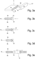
- Figure 3a shows in perspective view the open narrow side 4d - for example due to cutting this hollow chamber plate 4 to size - in which the core layer 4c consisting in this case of a plurality of spacer webs perpendicular to the main plane 4" of the plate 4 between the upper cover layer 4a and the lower cover layer 4b of the hollow chamber plate 4 is visible.
- this hollow chamber plate 4 consisting of a thermoplastic material is processed with a heatable forming tool 22, which reaches a temperature at which the material of the hollow chamber plate 4 does not yet become liquid, but is already deformable.
- This form tool 22 designed as a form bar, has in Figure 3a - d on one of its long sides a groove 23 with an in this case approximately semicircular cross-sectional contour and a width which is slightly wider than the thickness of the hollow chamber plate 4, which should be the same thickness everywhere.
- the forming tool 22 is pushed onto the open narrow side 4d in the heated state, so that the two cover layers 4a, b very quickly come into contact with the hot wall of the channel 23 and, with increasing heating during pressure along the plate plane 4", are deflected by the semicircular boundary walls of the channel 23 in the direction of the central plate plane 4", as in Figure 3c can be seen.
- the forming tool 22 is pushed on even further - which must be done slowly enough so that the affected parts of the hollow chamber plate 4 have time to heat up - the two cover layers 4a, b meet with their front free end edge at the bottom of the channel 23 and are welded together there.
- the webs 4c of the core layer are compressed in the area of the curvature of the forming tool 22 as well as the rounded front ends of the cover layer 4a, b and assume a wavy or zigzag shape.
- the hollow chamber plate 4 After the tool 22 has been removed and the hollow chamber plate 4 has cooled down, it now has a closed, semicircular, dense end edge and can be further processed, for example, joined to other plates.
- Figure 3e alternatively shows a rotatable forming roller as the forming tool 22, in which the groove 23 is arranged as an annular groove in its peripheral surface, and the deformation of the narrow side 4d takes place by slowly rolling the forming roller along this narrow side 4d with appropriate pressure.
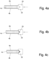
- This can be used, for example, for positive insertion into corresponding recesses of a plate running transversely to this plate, i.e. a T-constellation, as in principle in Figure 8a, b shown.
- FIGS. 5a to c show with analogous representations as the Figures 4a to c a molding strip 22 with a V-groove 24, the cross-sectional shape of which is also V-shaped, but has only one inclined flank 24b, while the other flank 24a of the V-groove 24 runs parallel to the sliding direction of the tool 22 to the lightweight panel, here hollow chamber panel 4, and thus parallel to the main plane 4" of the panel 4.
- a weld seam 17 or an adhesive seam 17 can be easily introduced, especially on the inside, if necessary and/or the outside, of the corner formation, e.g. by means of a hot glue gun 25, which dispenses molten plastic, in particular of the type of the cover layers of the lightweight panels.
- Figure 6a shows the inventive connection of two lightweight panels, here hollow chamber panels 4.1, 4.2, which according to Figures 3a to 3d have a semicircular end edge in cross-section.
- two lightweight panels here hollow chamber panels 4.1, 4.2, which according to Figures 3a to 3d have a semicircular end edge in cross-section.
- a concave groove is created on the inside and outside of the corner formation, into which a weld seam 17 or an adhesive seam 17 can easily be introduced.
- a light beam was installed at a desired location in the direction of view of the Figure 6c running V-groove 24 is incorporated, for example for producing a right-angled corner formation with an intermediate angle of 90° and with the bisector of the V-groove 24 perpendicular to the main plane 4" of this plate 4.
- V-groove 24 was introduced up to the inner side of one cover layer 4a, which was to remain continuous, and only the other cover layer 4b was penetrated by the V-groove 24.
- an adhesive surface 18 can be introduced between the approximate flanks of the V-groove 24 and/or a weld seam 17 can be introduced between the end edges of the cover layer sections 4b by means of a welding tool 25 or also an adhesive seam 17.
- Figure 7a shows how two lightweight panels in the form of hollow chamber panels 4.1, 4.2, which are to be welded together flush at their narrow sides, are welded together: To heat the narrow sides 4d, an electrically heated heating blade is usually placed between the two narrow sides 4d of the two plates 4.1, 4.2 and these are brought into contact with the hot heating blade until the narrow sides 4d have reached the dough temperature sufficient for mutual welding.
- the heating blade can then be removed and the two plates 4.1, 4.2 pushed together on the same base and pressed against each other with their heated narrow sides 4d according to Figure 7b , which creates a double-sized wall panel, for example.
Landscapes
- Engineering & Computer Science (AREA)
- Mechanical Engineering (AREA)
- Chemical & Material Sciences (AREA)
- Combustion & Propulsion (AREA)
- Transportation (AREA)
- Body Structure For Vehicles (AREA)
- Lining Or Joining Of Plastics Or The Like (AREA)
Claims (13)
- Carrosserie de coffre (1) de poids optimisé pour véhicules utilitaires, dans lequel la carrosserie de coffre (1) comprend une enveloppe de coffre (2) et un aménagement intérieur (3), dans lequel- l'enveloppe de coffre (2) comprend des parois (2a), en particulier également un toit (2b) et/ou un plancher (2c), qui se composent de panneaux légers avec des couches de recouvrement extérieures et une couche centrale du même matériau sous la forme de panneaux alvéolaires (4) en matière thermoplastique,- dans lequel l'aménagement intérieur (3) est constitué au moins partiellement du même matériau de panneau que l'enveloppe de coffre (2),- l'aménagement intérieur (3) est conçu et disposé de manière à améliorer la stabilité de l'enveloppe de coffre (2),- et la carrosserie de coffre (1) ne présente pas de profilés en métal léger sur les bords extérieurs de l'enveloppe de coffre (2),caractérisé en ce que,
dans le cas de panneaux alvéolaires (4.1, 4.2) se raccordant l'une à l'autre selon un angle- celles-ci sont placées l'une contre l'autre par leurs petits côtés (4d) et les couches de recouvrement respectives (4a, b) sont soudées ou collées l'une à l'autre,
dans lequel- soit les petits côtés (4d), vus en coupe transversale, sont arrondis avec des couches de recouvrement (4a, b) se touchant à l'intérieur d'un panneau, et des cordons de soudure (17) ou des cordons de collage (17) sont réalisés dans l'angle intérieur ou l'angle extérieur entre les deux arrondis,- soit les petits côtés (4d) sont biseautés, vus en coupe transversale, de sorte que, lorsque les panneaux (4.1, 4.2) sont placés l'un contre l'autre selon l'angle théorique, les surfaces inclinées (19) des petits côtés (4d) sont parallèles l'une à l'autre, dans lequel les surfaces inclinées sont soudées l'une à l'autre à l'extrémité intérieure et/ou extérieure des surfaces inclinées par rapport à l'angle, et en particulier les surfaces inclinées des panneaux sont collées l'une à l'autre au moyen de surfaces adhésives (18). - Carrosserie de coffre selon la revendication 1, dans lequel l'aménagement intérieur comprend des étagères (5, 6), en particulier- dans le cas d'étagères fixes (5), leurs fonds d'étagère (5a) sont réalisés à partir de panneaux légers, en particulier de panneaux alvéolaires (4), notamment les mêmes panneaux alvéolaires que les parois (2a), et sont soudés ou collés à la face intérieure de la paroi (2a), en particulier sont appliqués bord à bord contre la face intérieure de la paroi (2a) ou sont insérés dans celle-ci
et/ou- des étagères mobiles (6) avec des fonds d'étagère mobiles (6a), en particulier relevables, dans lesquels les fonds d'étagère (6a) sont constituées de panneaux légers, en particulier de panneaux alvéolaires (4), les supports de stockage (7) nécessaires à cet effet ou un châssis de stockage sont collés aux faces intérieures de la paroi (2a),- en particulier, les étagères (5, 6) disposées sur des côtés opposés sont entretoisées les unes par rapport aux autres. - Carrosserie de coffre selon l'une des revendications précédentes,
caractérisée en ce que- l'aménagement intérieur (3) comprend des parois intermédiaires (8), en particulier des parois intermédiaires (8) continues du sol au plafond, qui sont soudées ou collées à la paroi extérieure (2a) adjacente et/ou au panneau de toit (2b) et/ou au panneau de plancher (2c)
et/ou- dans le cas de parties de l'aménagement intérieur adjacentes au panneau de toit (2b) et/ou au panneau de plancher (2c) et/ou à la paroi extérieure, au moins un panneau de l'aménagement intérieur pénètre par complémentarité de forme dans le panneau de toit (2b) et/ou le panneau de plancher (2c) et/ou la paroi extérieure (2a),- notamment en la traversant jusqu'à sa couche de recouvrement extérieure (4a), et les deux parties sont soudées ou collées entre elles,- notamment les bords de contact des couches de recouvrement (4a, b) des deux parties sont soudées ou collées entre elles. - Carrosserie de coffre selon l'une des revendications précédentes,
caractérisée en ce que
l'aménagement intérieur ou l'enveloppe de coffre (2)- comprend des montants de roue (9)
et/ou- des marchepieds (13) sur des portes. - Carrosserie de coffre selon l'une des revendications précédentes,
caractérisée en ce que- au moins une porte d'accès (15, 16) est fabriquée sous forme de cadre,- aussi bien un cadre (15a1) d'un panneau de porte (15a, 16a) qu'un montant de porte (15b) ou, dans le cas de portes coulissantes, un guide de porte coulissante (16b) sont constitués de profilés en métal léger, en particulier de profilés en aluminium,- le panneau de porte (15a, 16a) est fabriqué à partir de panneaux légers, en particulier de panneaux alvéolaires (4), notamment les mêmes panneaux alvéolaires (4) que l'enveloppe de coffre (2)
et/ou- des panneaux de l'aménagement intérieur (3) s'étendant essentiellement à l'horizontale sont, à leur extrémité opposée à l'enveloppe, soutenus contre la flexion par une barre d'appui dont le profil de section transversale est vertical, en particulier en un panneau léger, en particulier un panneau alvéolaire. - Carrosserie de coffre selon l'une des revendications précédentes,
caractérisée en ce que
dans le cas d'un panneau alvéolaire coudé,- lorsque la couche de recouvrement (4a) est continue et courbée sur le côté extérieur de l'angle, les couches de recouvrement intérieures (4b) se touchent et sont reliées entre elles de manière étanche, en particulier soudées ou collées,- en particulier les couches centrales (4c) sont collées entre elles par l'intermédiaire d'une surface adhésive (18). - Carrosserie de coffre selon l'une des revendications précédentes,
caractérisée en ce que,
dans le cas de panneaux légers se raccordant les uns aux autres en forme de T, en particulier de panneaux alvéolaires (4.1, 4.2)- l'un des panneaux (4.1) est appliqué bout à bout contre le panneau continu (4.2) par son petit côté (4d) perpendiculaire à son plan principal (4") et est soudé à ce dernier au moins en ce qui concerne les extrémités de ses couches de recouvrement (4a, b), de préférence de manière circonférentielle, au panneau continu (4.2),- et en particulier sa couche centrale (4c) est collée à la couche centrale (4c) du panneau continu (4.2). - Carrosserie de coffre selon l'une des revendications précédentes,
caractérisée en ce que,
dans le cas de panneaux légers se raccordant les uns aux autres en forme de T, en particulier de panneaux alvéolaires (4.1, 4.2)- l'un des panneaux (4.1) s'enfonce dans un évidement (20) de forme correspondante du panneau continu (4.2),- au moins sur une ou plusieurs zones partielles de la longueur du panneau plongeant (4.1), en particulier- est soudée au panneau continu au moins en ce qui concerne les couches de recouvrement, de préférence sur tout le pourtour de celle-ci
et/ou- la zone plongeante (21) d'un panneau (4.1) est collée aux flancs (20a, b) de l'évidement dans le panneau continu (4.2),- en particulier, le petit côté (4b) du panneau plongeant (4.1) y a une section en forme de V ou de cône tronqué. - Carrosserie de coffre selon la revendication 5, de préférence en combinaison avec l'une des autres revendications précédentes,
caractérisée en ce que- au moins une autre pièce rapportée, notamment en métal léger, est fixée sur le cadre de porte (15a1), généralement en métal léger, notamment en aluminium, ou sur les guides de porte coulissante (16b), en plus du panneau de porte correspondant (15a, 16a),- en particulier une pièce rapportée pénétrant dans l'espace intérieur de la carrosserie,- notamment un support d'étagère (28) et/ou une poignée (27),
et/ou- dans le cas de panneaux légers se raccordant les uns aux autres en étant alignés avec leur plan principal (4"), en particulier de panneaux alvéolaires (4.1, 4.2), (4.1, 4.2), les panneaux sont collés ou soudés les uns aux autres par l'ensemble de leurs petits côtés. - Procédé de fabrication d'une carrosserie de coffre (1) selon l'une des revendications précédentes, dans lequel- l'enveloppe de coffre (2) ainsi qu'au moins une partie de l'aménagement intérieur (3) de la carrosserie de coffre (1) sont assemblées par soudage et/ou collage en utilisant des panneaux légers, sous forme de panneaux alvéolaires (4) en matière thermoplastique, pour former une carrosserie de coffre (1) d'une seule pièce,- en renonçant à des profilés métalliques incorporés au moins le long des bords extérieurs de l'enveloppe de coffre (2),- en particulier en renonçant à des profilés métalliques pour l'ensemble de la carrosserie de coffre (1),
dans lequel, pour la fabrication de panneaux alvéolaires (4.1, 4.2) se raccordant l'une à l'autre en formant un angle, celles-ci sont placées l'une contre l'autre par leurs petits côtés (4d) et les couches de recouvrement (4a, b) sont soudées ou collées l'une à l'autre, dans lequel- soit les petits côtés (4d) des panneaux alvéolaires (4.1, 4.2) appliquées l'une contre l'autre en formant un angle sont préalablement arrondis, vu en coupe transversale, avec des couches de recouvrement (4a, b) se touchant à l'intérieur d'un panneau (4), et des cordons de soudure (17) ou des cordons de collage (17) sont réalisés dans l'angle intérieur ou l'angle extérieur entre les deux arrondis,- soit les petits côtés (4d) sont biseautés, vus en coupe transversale, de sorte que, lorsque les panneaux (4.1, 4.2) sont placées l'une contre l'autre selon l'angle théorique, les surfaces inclinées (19) des petits côtés (4d) sont placées parallèlement l'une contre l'autre, les surfaces inclinées (19) étant soudées l'une à l'autre à l'extrémité intérieure et/ou extérieure des surfaces inclinées (19) par rapport à l'angle, et en particulier les surfaces inclinées (19) des panneaux (4) étant collées l'une à l'autre. - Procédé selon la revendication 10,
caractérisé en ce que
le petit côté (4d) d'un panneau léger, notamment d'un panneau alvéolaire (4), est fermé en ce que- un outil de formage (22) chauffé avec une rainure (23) dont la largeur correspond à l'épaisseur du panneau léger à fermer, en particulier du panneau alvéolaire (4), est glissé depuis le petit côté en direction du plan principal (4") du panneau (4) de plus en plus sur son petit côté ouvert (4d) ou est roulé comme un rouleau de formage le long de celui-ci, ce qui fait que les couches de recouvrement (4a, b) s'échauffent et sont pliées conformément au contour des flancs (23a, b) de la rainure (23),- jusqu'à ce que les bords d'extrémité libres des couches de recouvrement (4a, b) du panneau alvéolaire se touchent au fond de la rainure (23) et soient soudés entre eux par la température élevée correspondante de l'outil de formage (2). - Procédé selon l'une des revendications précédentes,
caractérisé en ce que,
pour la fabrication d'un panneau léger coudé, en particulier d'un panneau alvéolaire (4)- un panneau alvéolaire (4), après avoir réalisé une rainure en V (24) qui se termine avant la couche de recouvrement (4a) opposée et qui est réalisée en particulier par enlèvement de matière ou sous l'effet de la chaleur, est enroulé autour de la couche de recouvrement (4a) continue restante le long de la rainure en V (24), de préférence à l'état chauffé, et les bords de la rainure qui se touchent sont soudés ou collés pour former un panneau alvéolaire (4) coudé. - Procédé selon l'une des revendications précédentes,
caractérisé en ce que,
pour la fabrication de panneaux légers se raccordant les uns aux autres en forme de T, en particulier de panneaux alvéolaires (4.1, 4.2)- le panneau d'extrémité (4.1) est inséré dans un évidement (20) de forme correspondante du panneau continu (4.2),- au moins sur une ou plusieurs zones partielles de la longueur du panneau d'extrémité plongeant (4.1), en particulier- est soudée au panneau continu (4.2) au moins en ce qui concerne les couches de recouvrement (4a, b), de préférence sur tout le pourtour de celle-ci
et/ou- la zone plongeante (21) du panneau d'extrémité (4.1) est collée aux flancs (20a, b) de l'évidement (20) dans le panneau continu (4.2), dans lequel- le côté étroit du panneau plongeant (4.1) est auparavant configuré en forme de V ou de cône tronqué en section transversale.
Applications Claiming Priority (2)
| Application Number | Priority Date | Filing Date | Title |
|---|---|---|---|
| DE102021113321 | 2021-05-21 | ||
| DE102022100219.5A DE102022100219A1 (de) | 2021-05-21 | 2022-01-05 | Gewichtsoptimierter Kofferaufbau für Nutzfahrzeuge sowie Verfahren zu seiner Herstellung |
Publications (4)
| Publication Number | Publication Date |
|---|---|
| EP4091919A2 EP4091919A2 (fr) | 2022-11-23 |
| EP4091919A3 EP4091919A3 (fr) | 2023-02-22 |
| EP4091919B1 true EP4091919B1 (fr) | 2024-09-25 |
| EP4091919C0 EP4091919C0 (fr) | 2024-09-25 |
Family
ID=81580637
Family Applications (1)
| Application Number | Title | Priority Date | Filing Date |
|---|---|---|---|
| EP22171622.8A Active EP4091919B1 (fr) | 2021-05-21 | 2022-05-04 | Structure de coffre ayant un poids optimisé pour véhicules utilitaires, ainsi que son procédé de fabrication |
Country Status (1)
| Country | Link |
|---|---|
| EP (1) | EP4091919B1 (fr) |
Citations (1)
| Publication number | Priority date | Publication date | Assignee | Title |
|---|---|---|---|---|
| DE202020105789U1 (de) * | 2019-10-11 | 2021-02-02 | Elda Entwicklungsgesellschaft Mbh | Sicherheitskabine für ein Wohn- bzw. Reisemobil mit hochstabilen Wänden, welche bevorzugt Naturfasern umfassen |
Family Cites Families (11)
| Publication number | Priority date | Publication date | Assignee | Title |
|---|---|---|---|---|
| CN1102494C (zh) * | 1995-11-14 | 2003-03-05 | 岸本产业株式会社 | 合成树脂制中空板的融接方法 |
| AU5501899A (en) * | 1999-09-16 | 2001-04-17 | Rono Systemtechnik Ag | Method and device for the production of edge closures in sandwich panels |
| DE10005737C2 (de) * | 2000-02-09 | 2002-03-14 | Claus Reissig | Verfahren zum Verbinden von Mehrschichtplatten und Verbindung von mit Kanten aufeinanderstoßenden Mehrschichtplatten |
| GB2391841B (en) * | 2002-08-12 | 2005-12-07 | Adam Dale Ind Ltd | Caravan and construction method therefor |
| BE1017736A3 (nl) * | 2007-08-23 | 2009-05-05 | Callens Vincent Albert Georges | Verbeterde inrichting voor het transporteren van dieren. |
| US20100015392A1 (en) * | 2007-11-09 | 2010-01-21 | Molded Fiber Glass Companies | System and method for forming plastic pallets |
| EP2423081A1 (fr) * | 2010-08-30 | 2012-02-29 | Giraudon S.A.S. | Structure pour former une enceinte de stockage et procédé pour réaliser une telle structure |
| GB2534730A (en) * | 2013-09-11 | 2016-08-03 | Paradise Motor Homes Pty Ltd | Transportable body |
| GB2528668A (en) * | 2014-07-25 | 2016-02-03 | Daniel Muir | Method of Manufacturing A Structural Panel For An Engineering Structure |
| CN106428248A (zh) * | 2016-10-12 | 2017-02-22 | 杭州华聚复合材料有限公司 | 物流车车厢及其厢板总成装配结构 |
| SE542589C2 (sv) * | 2018-10-17 | 2020-06-09 | Ab Sjoelund Construction | Lådformigt lastutrymme för ett fordon och en anordning för stabilisering av bikakepaneler som ingår i lastutrymmet |
-
2022
- 2022-05-04 EP EP22171622.8A patent/EP4091919B1/fr active Active
Patent Citations (1)
| Publication number | Priority date | Publication date | Assignee | Title |
|---|---|---|---|---|
| DE202020105789U1 (de) * | 2019-10-11 | 2021-02-02 | Elda Entwicklungsgesellschaft Mbh | Sicherheitskabine für ein Wohn- bzw. Reisemobil mit hochstabilen Wänden, welche bevorzugt Naturfasern umfassen |
Also Published As
| Publication number | Publication date |
|---|---|
| EP4091919A2 (fr) | 2022-11-23 |
| EP4091919A3 (fr) | 2023-02-22 |
| EP4091919C0 (fr) | 2024-09-25 |
Similar Documents
| Publication | Publication Date | Title |
|---|---|---|
| DE10108287B4 (de) | Karosseriestruktur | |
| DE102016223492B3 (de) | Karosseriestruktur für ein Fahrzeug | |
| DE19544619C2 (de) | Schiebeverdeck für ein Lastfahrzeug | |
| DE102013105987B4 (de) | Fahrzeugaufbau | |
| WO2011124523A1 (fr) | Paroi extérieure pour une carrosserie de véhicule sur rail et son procédé de fabrication | |
| EP3849924A1 (fr) | Conteneur de produits en vrac | |
| DE19612342C1 (de) | Aufbau für Fahrzeuge | |
| DE19742772A1 (de) | Zwischenboden für einen Doppelstockwagen | |
| DE69021113T2 (de) | Eisenbahnpersonenwagenkasten und dessen Herstellungsverfahren. | |
| DE19843969A1 (de) | Verfahren und Vorrichtung zum Herstellen eines Kofferaufbaus sowie danach hergestellter Kofferaufbau | |
| DE4318838C2 (de) | Wandplatte für Fahrzeugaufbauten | |
| DE102022100219A1 (de) | Gewichtsoptimierter Kofferaufbau für Nutzfahrzeuge sowie Verfahren zu seiner Herstellung | |
| EP4091919B1 (fr) | Structure de coffre ayant un poids optimisé pour véhicules utilitaires, ainsi que son procédé de fabrication | |
| EP3590797A1 (fr) | Coffre doté d'une paroi raccordée à une structure de fond | |
| DE3027646A1 (de) | Ladebordwand | |
| EP3744617A1 (fr) | Châssis d'un véhicule utilitaire doté des longerons et des traverses | |
| EP0935932B1 (fr) | Etagère de stockage, en particulier pour le stockage de palettes chargées | |
| DE4334043A1 (de) | Wandkonstruktion für eine Kabine einer Lackieranlage | |
| EP3388317B1 (fr) | Construction de véhicule frigorifique | |
| EP4030542A1 (fr) | Boîtiers pour composants électriques, en particulier boîtiers pour batteries | |
| DE8113685U1 (de) | Kuehlcontainer | |
| DE69521366T2 (de) | Wandaufbau für transportfähige Einheiten | |
| DE3600783C2 (de) | Muldenaufbau für Fahrzeuge, insbesondere für Auflieger des Straßentransportes | |
| EP0861181B1 (fr) | Wagon a marchandises ferme | |
| DE9312345U1 (de) | Wohnmobil |
Legal Events
| Date | Code | Title | Description |
|---|---|---|---|
| PUAI | Public reference made under article 153(3) epc to a published international application that has entered the european phase |
Free format text: ORIGINAL CODE: 0009012 |
|
| STAA | Information on the status of an ep patent application or granted ep patent |
Free format text: STATUS: THE APPLICATION HAS BEEN PUBLISHED |
|
| AK | Designated contracting states |
Kind code of ref document: A2 Designated state(s): AL AT BE BG CH CY CZ DE DK EE ES FI FR GB GR HR HU IE IS IT LI LT LU LV MC MK MT NL NO PL PT RO RS SE SI SK SM TR |
|
| PUAL | Search report despatched |
Free format text: ORIGINAL CODE: 0009013 |
|
| AK | Designated contracting states |
Kind code of ref document: A3 Designated state(s): AL AT BE BG CH CY CZ DE DK EE ES FI FR GB GR HR HU IE IS IT LI LT LU LV MC MK MT NL NO PL PT RO RS SE SI SK SM TR |
|
| RIC1 | Information provided on ipc code assigned before grant |
Ipc: B29C 67/00 20060101ALI20230117BHEP Ipc: B29C 65/00 20060101ALI20230117BHEP Ipc: B29C 65/48 20060101ALI20230117BHEP Ipc: B29C 65/18 20060101ALI20230117BHEP Ipc: B62D 33/04 20060101AFI20230117BHEP |
|
| P01 | Opt-out of the competence of the unified patent court (upc) registered |
Effective date: 20230526 |
|
| STAA | Information on the status of an ep patent application or granted ep patent |
Free format text: STATUS: REQUEST FOR EXAMINATION WAS MADE |
|
| 17P | Request for examination filed |
Effective date: 20230804 |
|
| RBV | Designated contracting states (corrected) |
Designated state(s): AL AT BE BG CH CY CZ DE DK EE ES FI FR GB GR HR HU IE IS IT LI LT LU LV MC MK MT NL NO PL PT RO RS SE SI SK SM TR |
|
| GRAP | Despatch of communication of intention to grant a patent |
Free format text: ORIGINAL CODE: EPIDOSNIGR1 |
|
| STAA | Information on the status of an ep patent application or granted ep patent |
Free format text: STATUS: GRANT OF PATENT IS INTENDED |
|
| INTG | Intention to grant announced |
Effective date: 20240424 |
|
| GRAS | Grant fee paid |
Free format text: ORIGINAL CODE: EPIDOSNIGR3 |
|
| GRAA | (expected) grant |
Free format text: ORIGINAL CODE: 0009210 |
|
| STAA | Information on the status of an ep patent application or granted ep patent |
Free format text: STATUS: THE PATENT HAS BEEN GRANTED |
|
| AK | Designated contracting states |
Kind code of ref document: B1 Designated state(s): AL AT BE BG CH CY CZ DE DK EE ES FI FR GB GR HR HU IE IS IT LI LT LU LV MC MK MT NL NO PL PT RO RS SE SI SK SM TR |
|
| REG | Reference to a national code |
Ref country code: GB Ref legal event code: FG4D Free format text: NOT ENGLISH |
|
| REG | Reference to a national code |
Ref country code: CH Ref legal event code: EP |
|
| REG | Reference to a national code |
Ref country code: DE Ref legal event code: R096 Ref document number: 502022001729 Country of ref document: DE |
|
| REG | Reference to a national code |
Ref country code: IE Ref legal event code: FG4D Free format text: LANGUAGE OF EP DOCUMENT: GERMAN |
|
| U01 | Request for unitary effect filed |
Effective date: 20241015 |
|
| P04 | Withdrawal of opt-out of the competence of the unified patent court (upc) registered |
Free format text: CASE NUMBER: APP_58875/2024 Effective date: 20241028 |
|
| U07 | Unitary effect registered |
Designated state(s): AT BE BG DE DK EE FI FR IT LT LU LV MT NL PT RO SE SI Effective date: 20241031 |
|
| PG25 | Lapsed in a contracting state [announced via postgrant information from national office to epo] |
Ref country code: NO Free format text: LAPSE BECAUSE OF FAILURE TO SUBMIT A TRANSLATION OF THE DESCRIPTION OR TO PAY THE FEE WITHIN THE PRESCRIBED TIME-LIMIT Effective date: 20241225 |
|
| PG25 | Lapsed in a contracting state [announced via postgrant information from national office to epo] |
Ref country code: GR Free format text: LAPSE BECAUSE OF FAILURE TO SUBMIT A TRANSLATION OF THE DESCRIPTION OR TO PAY THE FEE WITHIN THE PRESCRIBED TIME-LIMIT Effective date: 20241226 |
|
| PG25 | Lapsed in a contracting state [announced via postgrant information from national office to epo] |
Ref country code: RS Free format text: LAPSE BECAUSE OF FAILURE TO SUBMIT A TRANSLATION OF THE DESCRIPTION OR TO PAY THE FEE WITHIN THE PRESCRIBED TIME-LIMIT Effective date: 20241225 |
|
| PG25 | Lapsed in a contracting state [announced via postgrant information from national office to epo] |
Ref country code: RS Free format text: LAPSE BECAUSE OF FAILURE TO SUBMIT A TRANSLATION OF THE DESCRIPTION OR TO PAY THE FEE WITHIN THE PRESCRIBED TIME-LIMIT Effective date: 20241225 Ref country code: NO Free format text: LAPSE BECAUSE OF FAILURE TO SUBMIT A TRANSLATION OF THE DESCRIPTION OR TO PAY THE FEE WITHIN THE PRESCRIBED TIME-LIMIT Effective date: 20241225 Ref country code: GR Free format text: LAPSE BECAUSE OF FAILURE TO SUBMIT A TRANSLATION OF THE DESCRIPTION OR TO PAY THE FEE WITHIN THE PRESCRIBED TIME-LIMIT Effective date: 20241226 |
|
| PG25 | Lapsed in a contracting state [announced via postgrant information from national office to epo] |
Ref country code: IS Free format text: LAPSE BECAUSE OF FAILURE TO SUBMIT A TRANSLATION OF THE DESCRIPTION OR TO PAY THE FEE WITHIN THE PRESCRIBED TIME-LIMIT Effective date: 20250125 |
|
| PG25 | Lapsed in a contracting state [announced via postgrant information from national office to epo] |
Ref country code: SM Free format text: LAPSE BECAUSE OF FAILURE TO SUBMIT A TRANSLATION OF THE DESCRIPTION OR TO PAY THE FEE WITHIN THE PRESCRIBED TIME-LIMIT Effective date: 20240925 |
|
| PG25 | Lapsed in a contracting state [announced via postgrant information from national office to epo] |
Ref country code: ES Free format text: LAPSE BECAUSE OF FAILURE TO SUBMIT A TRANSLATION OF THE DESCRIPTION OR TO PAY THE FEE WITHIN THE PRESCRIBED TIME-LIMIT Effective date: 20240925 |
|
| PG25 | Lapsed in a contracting state [announced via postgrant information from national office to epo] |
Ref country code: PL Free format text: LAPSE BECAUSE OF FAILURE TO SUBMIT A TRANSLATION OF THE DESCRIPTION OR TO PAY THE FEE WITHIN THE PRESCRIBED TIME-LIMIT Effective date: 20240925 Ref country code: CZ Free format text: LAPSE BECAUSE OF FAILURE TO SUBMIT A TRANSLATION OF THE DESCRIPTION OR TO PAY THE FEE WITHIN THE PRESCRIBED TIME-LIMIT Effective date: 20240925 |
|
| PG25 | Lapsed in a contracting state [announced via postgrant information from national office to epo] |
Ref country code: SK Free format text: LAPSE BECAUSE OF FAILURE TO SUBMIT A TRANSLATION OF THE DESCRIPTION OR TO PAY THE FEE WITHIN THE PRESCRIBED TIME-LIMIT Effective date: 20240925 |
|
| U20 | Renewal fee for the european patent with unitary effect paid |
Year of fee payment: 4 Effective date: 20250428 |
|
| PGFP | Annual fee paid to national office [announced via postgrant information from national office to epo] |
Ref country code: CH Payment date: 20250601 Year of fee payment: 4 |
|
| PLBE | No opposition filed within time limit |
Free format text: ORIGINAL CODE: 0009261 |
|
| STAA | Information on the status of an ep patent application or granted ep patent |
Free format text: STATUS: NO OPPOSITION FILED WITHIN TIME LIMIT |
|
| 26N | No opposition filed |
Effective date: 20250626 |
|
| PG25 | Lapsed in a contracting state [announced via postgrant information from national office to epo] |
Ref country code: HR Free format text: LAPSE BECAUSE OF FAILURE TO SUBMIT A TRANSLATION OF THE DESCRIPTION OR TO PAY THE FEE WITHIN THE PRESCRIBED TIME-LIMIT Effective date: 20240925 |
|
| PG25 | Lapsed in a contracting state [announced via postgrant information from national office to epo] |
Ref country code: MC Free format text: LAPSE BECAUSE OF FAILURE TO SUBMIT A TRANSLATION OF THE DESCRIPTION OR TO PAY THE FEE WITHIN THE PRESCRIBED TIME-LIMIT Effective date: 20240925 |
|
| PG25 | Lapsed in a contracting state [announced via postgrant information from national office to epo] |
Ref country code: IE Free format text: LAPSE BECAUSE OF NON-PAYMENT OF DUE FEES Effective date: 20250504 |