EP4091925A1 - Dispositif d'acheminement d'au moins un tuyau flexible dans un véhicule à volant - Google Patents
Dispositif d'acheminement d'au moins un tuyau flexible dans un véhicule à volant Download PDFInfo
- Publication number
- EP4091925A1 EP4091925A1 EP22173486.6A EP22173486A EP4091925A1 EP 4091925 A1 EP4091925 A1 EP 4091925A1 EP 22173486 A EP22173486 A EP 22173486A EP 4091925 A1 EP4091925 A1 EP 4091925A1
- Authority
- EP
- European Patent Office
- Prior art keywords
- tube
- line
- spiral
- lines
- steerer tube
- Prior art date
- Legal status (The legal status is an assumption and is not a legal conclusion. Google has not performed a legal analysis and makes no representation as to the accuracy of the status listed.)
- Granted
Links
Images


Classifications
-
- B—PERFORMING OPERATIONS; TRANSPORTING
- B62—LAND VEHICLES FOR TRAVELLING OTHERWISE THAN ON RAILS
- B62K—CYCLES; CYCLE FRAMES; CYCLE STEERING DEVICES; RIDER-OPERATED TERMINAL CONTROLS SPECIALLY ADAPTED FOR CYCLES; CYCLE AXLE SUSPENSIONS; CYCLE SIDECARS, FORECARS, OR THE LIKE
- B62K19/00—Cycle frames
- B62K19/30—Frame parts shaped to receive other cycle parts or accessories
- B62K19/32—Steering heads
-
- B—PERFORMING OPERATIONS; TRANSPORTING
- B62—LAND VEHICLES FOR TRAVELLING OTHERWISE THAN ON RAILS
- B62J—CYCLE SADDLES OR SEATS; AUXILIARY DEVICES OR ACCESSORIES SPECIALLY ADAPTED TO CYCLES AND NOT OTHERWISE PROVIDED FOR, e.g. ARTICLE CARRIERS OR CYCLE PROTECTORS
- B62J11/00—Supporting arrangements specially adapted for fastening specific devices to cycles, e.g. supports for attaching maps
- B62J11/10—Supporting arrangements specially adapted for fastening specific devices to cycles, e.g. supports for attaching maps for mechanical cables, hoses, pipes or electric wires, e.g. cable guides
- B62J11/19—Supporting arrangements specially adapted for fastening specific devices to cycles, e.g. supports for attaching maps for mechanical cables, hoses, pipes or electric wires, e.g. cable guides specially adapted for electric wires
Definitions
- the invention relates to a device for guiding at least one flexible line in the annular space between a head tube of a vehicle frame and a steerer tube of a steering fork rotatably mounted in the head tube.
- the invention also relates to the use of such a device for guiding lines, as well as two-, three- and four-wheelers equipped with such a device.
- the handlebar is connected via a steerer tube to a handlebar fork, which is connected directly or via a suspension to a front wheel of the vehicle.
- the steerer tube is rotatably mounted in a control tube, which is part of a vehicle frame.
- flexible lines that are routed from the area of the fork and handlebars to the frame have mostly been routed on the outside of these components, because due to the relative movement between the head tube/vehicle frame on the one hand and the steerer tube/fork/handlebars on the other (rotations of up to +/ - 180° and more) guidance inside is problematic.
- “flexible” lines are understood to mean lines for electricity, signals, lights, hydraulic oil or steel cables (Bowden cables) which are not rigid, ie can be elastically deformed.
- the lines can be single-core or multi-core, or several different or even different types of lines can be brought together.
- Lines routed inside the head tube are routed parallel to the axis of the steerer tube.
- a line guide for a bicycle is known in which a sleeve or cuff is arranged in the annular space between the head tube and the steerer tube, which prevents frictional contact of the lines with the inner steerer tube when the steering is turned.
- the US 2019/0061864 A1 discloses a telescoping handlebar arrangement for two-wheelers, in which spiral lines are guided inside the inner telescoping shaft in order to compensate for length changes between the two ends of the shaft elements that are axially telescoping relative to one another, with frictional and thus wearing contact between the spiral line and the surrounding inner wall of the shaft not being prevented becomes.
- the object of the invention is to provide a structurally simple device for the protected or concealed routing of at least one flexible line in the area of a steerer tube inside a vehicle frame.
- the movements of the line that occur in the process should not lead to damage to the line and restoring forces due to deformation of the line should be largely avoided.
- the device has at least one Shaped element for forming at least one partial helical guide of at least one turn for the at least one line in the annular space.
- the shaped element has the shape of a helical screw.
- a large number of individual projections can be provided, the sequence or attachment of which wraps the at least one line in a spiral or helical arrangement around the steerer tube with at least one revolution.
- the length of the line does not change for the relative rotary movement, ie there is no lengthening or compression, only the diameter of the helical spiral changes.
- a rotational movement of the fork in the head tube is compensated for or bridged by the expansion or contraction of the spiral windings of the line.
- this is half a turn.
- either the cable must be wound loosely in the guide channel to absorb the turning movement of +/- 180° or it is wound up tightly in an end position that corresponds to an end position of the handlebar turning movement (e.g. rotated 180° from the straight-ahead position).
- an end position of the handlebar turning movement e.g. rotated 180° from the straight-ahead position.
- the arrangement is preferably chosen so that the spiral line is in a relaxed state when the handlebars are in a “straight ahead” position.
- the device is designed with multiple threads for different lines.
- Each helix can have its own wire that will not collide with another wire in a different helix, reducing the risk of damage in long-term use.
- the helical guides for two lines are arranged axially one behind the other.
- the two lines can be arranged axially one behind the other completely separately from one another.
- This design requires more axial space, but a narrow annular gap between the head tube and the steerer tube.
- the helical guides for two lines are arranged radially one above the other. This design requires less axial space, but a wider annular gap between the head tube and steerer tube.
- each guide has at least 3, preferably between 4 and 12, particularly preferably 5 to 8 turns.
- the device consists of an internal structure from which a helical surface (helicoid) extends radially outward.
- a structurally simple and compact arrangement is provided, which can be charged with the line in a simple manner. This is done by inserting the line into the helical guide, preferably a channel.
- the device consists of an inner structure and an outer sleeve, between which the Helical surface (36) extends. As a result, the line is protected inside the device.
- the outer sleeve can be pushed onto the inner sleeve or the helical surface.
- the inner structure has an axial end cap at one axial end and the outer sleeve at the other axial end to reduce the ingress of debris and dirt.
- the top end cap is attached to the inner structure and the bottom end cap is attached to the outer sleeve.
- a top conduit opening for the at least one conduit to pass through is formed in the top end cap.
- a lower conduit opening for passage of the at least one conduit is located in the outer sleeve near the bottom end cap.
- the upper end cover can also be connected to the outer shell and the lower end cover can be connected to the inner shell.
- the helical surface can also be attached to or formed on the outer shell and protrude inwards.
- the device is designed as a flexible spiral tube, the first end of which is fixed to the control tube and the second end of which is fixed to the steerer tube.
- the spiral tube has a longitudinal slit which is preferably arranged on the outside of the spiral tube and is closed in the normal state, ie is opened by elastically bending apart the slit edges in order to insert the line.
- the slit then closes due to the elastic return movement of the slit edges into the starting position, so that the line can no longer escape during use.
- the device is designed as an injection molded part, which is formed by overmolding the spirally arranged line with a flexible plastic, with a first end of the injection molded part being fixed to the control tube and a second end to the steerer tube is.
- a finished component consisting of a pipe with the spiral injection molded part can be produced, which is easier to install in a vehicle and is suitable for mass production.
- the object on which the invention is based is also achieved in that the spiraling of the flexible line is permanently produced by supplying heat.
- the device is designed as a multi-part sleeve with guide projections formed on the outer circumference and lying on a spiral line on the circumference of the sleeve.
- the line is placed between the preferably pin-like projections in a spiral shape.
- the projections or pins have such a radial extent that the line cannot protrude radially beyond the projections in the event of maximum deformation.
- guide projections are formed directly on the steerer tube, ie they are also produced during the manufacturing process of the steerer tube.
- the object on which the invention is based is also achieved in that the device is designed as a spiral spring, the first end of which is fixed to the control tube and the second end of which is fixed to the steerer tube, and the at least one line can be fastened to the spiral spring, for example by means of cable ties.
- the spiral spring and the line form a component that moves together.
- the spiral spring consists of spring steel or a plastic spiral.
- the version made of spring steel is more space-saving and durable, the version made of plastic is easier to produce if there is a sufficient number of pieces and can advantageously have fastening means for the line formed on it.
- the invention also relates to a two-wheeler, which has a device according to the invention mounted according to one or more aspects or embodiments. These include bicycles, e-bikes, pedelecs or two-wheeled cargo bikes.
- the invention also relates to a tricycle which has a device according to the invention mounted according to one or more aspects or embodiments. These include children's tricycles, three-wheeled cargo bikes and motorized so-called trikes.
- the invention also relates to a four-wheeled vehicle with handlebars, such as a four-wheeled cargo bike or a quad, which has a device according to the invention installed according to one or more aspects or embodiments.
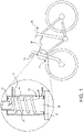
- figure 1 shows a vehicle frame 10 of a two-wheeler 12, the front end of which has a head tube 14 in which a steerer tube 16 of a handlebar fork 18 is rotatably mounted.
- the vehicle frame 10 has at least one bore 20 for the passage of a flexible line 22, which is located in an annular space 23 between the head tube 14 and the steerer tube 16 and should not be damaged when the handlebar fork 18 rotates relative to the vehicle frame 10.
- the steerer tube 16 has a bore 21 for the passage of the line 22 into the interior of the steerer tube 16 and for forwarding upwards.
- the line 22 can be a current-carrying line, e.g. for lighting or a hydraulic line for brakes or hydraulic suspension, fiber optic lines or Bowden cables. It can also be a signal line for controlling electronic devices.
- the line 22 can be single-core or multi-core or several different or even different types of lines 22a, 22b can be brought together.
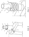
- FIG 2 shows a perspective view of a first embodiment of a line routing device 24a according to the invention, of which in this figure an outer sleeve 26 and an upper end cover 28 with an upper opening 30 for the passage of the line 22, which is designed as a two-wire line by way of example, and a lower opening 32 for the same line 22 are shown.
- the bore 21 for the passage of the flexible line 22 into the interior of the steerer tube 16 is formed in the steerer tube 16 .
- the bore 21 and the opening 30 are preferably one behind the other in the axial direction. It should be noted that the invention does not require a line to be routed inside the steerer tube 16, but rather the line 22 can also be routed upwards on the outside next to the steerer tube 16, in which case the bore 21 is of course omitted.
- FIG 3 the same device 24a without the outer sleeve 26 is shown.
- a sleeve-like inner structure (inner sleeve) 34 can be seen, which encloses the steerer tube 16 in such a way that the inner sleeve 34 rotates with each rotation of the steerer tube 16 . This can be done by means of positive or frictional locking or gluing or by Fastened with a screw.
- the inner structure 34 does not have to be a sleeve, it can also be an annular lattice structure.
- the upper end cover 28 is formed on the inner structure/inner sleeve 34 .
- Attached or molded to or abutting the inner sleeve 34 is a helical guide in the form of a helical surface 36 (helicoids) having three turns.
- the helical surface has four turns, resulting in figure 4 is better recognizable.
- the steerer tube 16 can have a conical section because of a control bearing and accordingly the inner sleeve 34 is also conical in this area 38, whereby a frictional connection can be made by axially pressing the inner sleeve 34 onto the steerer tube 16.
- a single helical surface 36 for forming a guide channel for a line 22 is shown in the line guiding device 24a. It is alternatively possible within the scope of the invention to provide several helical surfaces to form a multi-start screw or several channels for the individual routing of several lines 22 .
- a collar 39 is shown in dashed lines, which would be arranged along the outer edge of the entire helical surface 36 in an alternative embodiment that dispenses with an outer sleeve 26 and thus represents a radial outer stop for the line 22 .
- FIG 5 an axial section of this line guiding device 24a is shown, where it can be seen that a lower end cover 40 is formed on the outer sleeve 26, whereby this device is closed except for the two openings 30, 32 ( figure 2 ) represents a closed structure.
- the outer sleeve 26 is fitted in the control tube 14 in a form-fitting or force-fitting manner by means of fixing means (not shown) and is therefore firmly connected to the vehicle frame 10 .
- the "outer sleeve" can also be part of the frame or omitted entirely.
- the inner sleeve 34 and the helical surface 36 are non-rotatably connected to the steerer tube 16 and rotate when the handlebar is actuated. Therefore, when the steering wheel is turned, a relative rotary movement occurs between the helical surface 36 and the outer sleeve 26 and thus also between the upper 30 and lower 32 opening.
- the outer sleeve 26 is arranged in the control tube 14 in such a way that the bore 20 ( figure 1 ) is flush with the lower opening 32 so that the portion of the conduit 22 exiting through the lower opening 32 passes through the bore 20 ( figure 1 ) can be performed.
- the line 22 is guided between the helical surface 36 approximately spatially radially in the middle between the inner sleeve 34 and the outer sleeve 26 (inner sleeve 34 and outer sleeve 26 and helical surface 36 together form a guide or a channel for the line), so that with a Movement of the handlebars due to the relative rotation between the inner sleeve 34 and the outer sleeve 26 is in one case pulled on the line 22 and this then nestles more closely against the inner sleeve 34 and in the other case is pressed, so that the spiral radius of the line 22 increases somewhat and this above all closer to the outer sleeve 26 in the upper area.
- the line 22 is fixed in the area of the two openings 30, 32 to the associated components 34, 26 (or the bore 20 and the bore 21) using fixing means (e.g. cable ties) that are not shown in detail, so that the movement of the line 22 can only take place inside the Device 24a takes place.
- fixing means e.g. cable ties
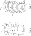
- FIGS Figures 6 and 7 A second embodiment of a line guiding device 24b is shown in FIGS Figures 6 and 7 shown in figure 6 without and in figure 7 with the line 22.
- This embodiment differs from the first embodiment of a line guiding device 24a in that there is no helical surface and instead, preferably pin-like guide projections 44 project outwards from the sleeve 42, which lie on a spiral line 46 and thus guide the line 22 between the pins 44 ensure.
- the pins 44 can be aligned radially, but can also run obliquely to the central axis. Also, the pins 44 can be straight, but also have another (preferably curved or hook-like) shape.
- this configuration 24b comprises an additional outer sleeve 26 (not shown) in the same way as the first embodiment 24a in order to form a closed shape for the conduit 22.
- the outer sleeve 26 can be omitted.
- a third embodiment of a line routing device 24c is in figure 8 shown similar to the second embodiment 24b ( Figure 6 and 7 ) is, with the difference that a sleeve (34, 42) is completely dispensed with and rather pins 48 are formed directly on the steerer tube 16.
- the line (not shown) is attached to the top pin 48a (e.g. by means of a cable tie) and runs underneath it spirally, surrounding the steerer tube 16 at a distance to the bottom pin 48b and runs from there into the bore 20 in the vehicle frame 10 ( figure 1 ).
- the pins 48 have a sufficient radial length so that the center point of the line 22 cannot protrude beyond the end of the pins 48 under any circumstances.
- the pins 48 are preferably pressed into prefabricated holes on the circumference of the steerer tube. The pins 48 could end up too have an upstanding hooked end to prevent slipping off the pins 48.
- a fourth embodiment of a line guiding device 24d is in figure 9 shown, which is designed as an elastic spiral tube 50, the lower end 52a is attached to the vehicle frame 10 in the region of the bore 20 and the upper end 52b further up on the steerer tube 16, for example by means of a cable tie.
- the line 22 can be fixed in the bore 20 in the frame 10 and the bore 21 in the steerer tube 16 by means of a grommet 56 .
- the spiral tube 50 has a sufficiently large diameter so that the line 22 can be pushed through.
- the elastic spiral tube 50 in the longitudinal direction with a continuous longitudinal slit 54 (shown only in a small section), which is closed in the normal state but can be opened for the insertion of the line 22.
- the longitudinal slot 54 is preferably not arranged on the radial outside of the spiral tube 50 with respect to the direction of the coil, so that the line 22 does not rub against the slot 54 and is damaged.
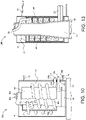
- FIG 10 shows a line guide device 24e for two separate flexible lines 22a, 22b, which are radially separated from one another and guided parallel to one another in two elastically inherently rigid spiral tubes 50a, 50b, specifically an outer line 22a and an inner line 22b separated by a separating sleeve 55.
- the separating tube 55 is not necessary but preferred in order to separate the two spiral tubes 50a, 50b.
- Both spiral tubes 50a, 50b enter through separate bores 20a, 20b through the control tube 14 into the annular space between the control tube 14 and the steerer tube 16 and through bores 21a, 21b into the interior of the steerer tube 16.
- the separating sleeve 55 is attached to the steerer tube 16 . This requires a bore 57 for the passage of the outer line 22a.
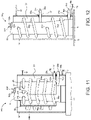
- figure 11 shows a further embodiment of a line guiding device 24f, which is essentially that of FIG figure 10 is the same with the difference that the two flexible lines 22a, 22b are not guided parallel to one another but in opposite directions to one another, ie one rotating to the left and the other rotating to the right.
- figure 12 shows a further embodiment of a line routing device 24g, in which two flexible lines 22a, 22b are routed axially one behind the other. These pass over vertically spaced bores 20a, 20b through the head tube 14 and through similarly spaced bores 21a, 21b into the interior of the steerer tube 16.
- the lines have approximately 2.8 turns.
- the bore 20a for the passage of the upper flexible line 22a is preferably located slightly above the bore 21b for the passage of the lower line 22b into the steerer tube 16, in which these are continued upwards.
- figure 13 shows a further embodiment of a line guiding device 24h similar to that of FIG figure 5 , in which a helical surface 58 is formed on the outer sleeve 26 and projects inward, so that an inner sleeve (34 in figure 5 ) can be omitted.
- the helical surface 58 formed on the outer sleeve 26 projects almost as far as the steerer tube 16 while maintaining a narrow slit of a few millimeters. It would also be possible in this training, a collar similar to collar 39 of figure 4 be provided to prevent the line 22 from rubbing against the steerer tube 16.
Landscapes
- Engineering & Computer Science (AREA)
- Mechanical Engineering (AREA)
- Steering Devices For Bicycles And Motorcycles (AREA)
- Flexible Shafts (AREA)
Applications Claiming Priority (1)
| Application Number | Priority Date | Filing Date | Title |
|---|---|---|---|
| DE102021112908.7A DE102021112908B3 (de) | 2021-05-18 | 2021-05-18 | Vorrichtung zur Führung mindestens einer flexiblen Leitung bei einem Lenkerfahrzeug |
Publications (3)
| Publication Number | Publication Date |
|---|---|
| EP4091925A1 true EP4091925A1 (fr) | 2022-11-23 |
| EP4091925C0 EP4091925C0 (fr) | 2024-07-17 |
| EP4091925B1 EP4091925B1 (fr) | 2024-07-17 |
Family
ID=81654579
Family Applications (1)
| Application Number | Title | Priority Date | Filing Date |
|---|---|---|---|
| EP22173486.6A Active EP4091925B1 (fr) | 2021-05-18 | 2022-05-16 | Dispositif d'acheminement d'au moins un tuyau flexible dans un véhicule à volant |
Country Status (2)
| Country | Link |
|---|---|
| EP (1) | EP4091925B1 (fr) |
| DE (1) | DE102021112908B3 (fr) |
Citations (9)
| Publication number | Priority date | Publication date | Assignee | Title |
|---|---|---|---|---|
| DE102007054952A1 (de) | 2007-11-17 | 2009-05-28 | Tyco Electronics Amp Gmbh | Wickelfeder |
| US20100194073A1 (en) * | 2007-10-01 | 2010-08-05 | Graham Corbin | Mechanical linkages between moving machine parts |
| DE102013204556A1 (de) | 2012-03-16 | 2013-09-19 | Specialized Bicycle Components, Inc. | Fahrrad mit integrierter Kabelführung |
| US9174695B1 (en) * | 2014-07-10 | 2015-11-03 | Neco Technology Industry Co., Ltd. | Head parts assembly for a bicycle with a cable collecting device |
| US9409618B2 (en) * | 2014-04-18 | 2016-08-09 | Look Cycle International | Guide device for a flexible linking member passing into a bicycle frame |
| DE102015214491A1 (de) | 2015-07-30 | 2017-02-02 | Mike Ambach | Elektrische Verbindung zur Übertragung von Strom und/oder elektrischen Signalen |
| DE202016102087U1 (de) | 2016-04-20 | 2017-05-26 | Igus Gmbh | Leitungsführungssystem für mindestens eine auf- und abspulbare Versorgungsleitung sowie Drehführung hierfür |
| US20190061864A1 (en) | 2017-08-29 | 2019-02-28 | Brake Force One Gmbh | Height-adjustable steering device for small vehicles |
| DE202018101912U1 (de) | 2018-04-09 | 2019-07-10 | Zeg Zweirad-Einkaufs-Genossenschaft Eg | Gabel-Rahmen-Einheit |
Family Cites Families (1)
| Publication number | Priority date | Publication date | Assignee | Title |
|---|---|---|---|---|
| US9242692B2 (en) | 2014-03-17 | 2016-01-26 | Shimano Inc. | Compression ring and head parts |
-
2021
- 2021-05-18 DE DE102021112908.7A patent/DE102021112908B3/de active Active
-
2022
- 2022-05-16 EP EP22173486.6A patent/EP4091925B1/fr active Active
Patent Citations (9)
| Publication number | Priority date | Publication date | Assignee | Title |
|---|---|---|---|---|
| US20100194073A1 (en) * | 2007-10-01 | 2010-08-05 | Graham Corbin | Mechanical linkages between moving machine parts |
| DE102007054952A1 (de) | 2007-11-17 | 2009-05-28 | Tyco Electronics Amp Gmbh | Wickelfeder |
| DE102013204556A1 (de) | 2012-03-16 | 2013-09-19 | Specialized Bicycle Components, Inc. | Fahrrad mit integrierter Kabelführung |
| US9409618B2 (en) * | 2014-04-18 | 2016-08-09 | Look Cycle International | Guide device for a flexible linking member passing into a bicycle frame |
| US9174695B1 (en) * | 2014-07-10 | 2015-11-03 | Neco Technology Industry Co., Ltd. | Head parts assembly for a bicycle with a cable collecting device |
| DE102015214491A1 (de) | 2015-07-30 | 2017-02-02 | Mike Ambach | Elektrische Verbindung zur Übertragung von Strom und/oder elektrischen Signalen |
| DE202016102087U1 (de) | 2016-04-20 | 2017-05-26 | Igus Gmbh | Leitungsführungssystem für mindestens eine auf- und abspulbare Versorgungsleitung sowie Drehführung hierfür |
| US20190061864A1 (en) | 2017-08-29 | 2019-02-28 | Brake Force One Gmbh | Height-adjustable steering device for small vehicles |
| DE202018101912U1 (de) | 2018-04-09 | 2019-07-10 | Zeg Zweirad-Einkaufs-Genossenschaft Eg | Gabel-Rahmen-Einheit |
Also Published As
| Publication number | Publication date |
|---|---|
| EP4091925C0 (fr) | 2024-07-17 |
| EP4091925B1 (fr) | 2024-07-17 |
| DE102021112908B3 (de) | 2022-10-13 |
Similar Documents
| Publication | Publication Date | Title |
|---|---|---|
| DE69824369T2 (de) | Einstellvorrichtung für Bowdenzug | |
| EP2991887B1 (fr) | Mecanisme de direction | |
| EP3681750B1 (fr) | Dispositif de fermeture pour fermer une ouverture de passage dans une carrosserie de véhicule et véhicule équipé d'un tel dispositif de fermeture | |
| DE102014113842B4 (de) | Umwerfer | |
| DE19539864C1 (de) | Zahnstangengetriebe | |
| DE29924278U1 (de) | Radschützer für Zweiräder | |
| DE60027129T2 (de) | Vorrichtung zum Schützen eines Kabels | |
| DE202019104749U1 (de) | Lenkervorbau mit integrierter Zugführung | |
| EP3260361B1 (fr) | Corps de guide de câble | |
| DE102021112908B3 (de) | Vorrichtung zur Führung mindestens einer flexiblen Leitung bei einem Lenkerfahrzeug | |
| EP4140865A1 (fr) | Élément de routage de câbles pour un cadre de bicyclette | |
| DE102018006153B4 (de) | Steuersatz zur rotierbaren Lagerung eines Gabelschaftes | |
| DE202021000494U1 (de) | Einklappbarer Lenker | |
| EP2881314B1 (fr) | Poignée de vélo | |
| DE4420125C2 (de) | Drehgriffschalter für Fahrräder | |
| DE29608010U1 (de) | Gehäuse für einen Betätigungszug zum Schalten der Gangstufen eines Fahrradgetriebes | |
| DE102017201995B4 (de) | Fahrradrahmen-Steuerrohr | |
| EP1273507B1 (fr) | Poignée tournante pour un organe de commande de bicyclette | |
| DE602005005387T2 (de) | Vorrichtung zum Aufspulen von Kabeln | |
| DE102019119565A1 (de) | Fahrzeug, insbesondere Zweiradfahrzeug, und Radgabel-Vorbau-Kombination | |
| WO2017029310A1 (fr) | Guidon de motocyclette | |
| EP3718872B1 (fr) | Véhicule, en particulier véhicule à deux roues et unité de potence de guidon | |
| DE29619084U1 (de) | Mechanische Sperrvorrichtung für Fahrräder | |
| EP4303110A1 (fr) | Système de limitation de l'angle de braquage directionnel d'une bicyclette et/ou d'un motocycle, ainsi que bicyclette et/ou motocycle doté d'un tel système | |
| DE10234813A1 (de) | Spannschloss für Kabelzug |
Legal Events
| Date | Code | Title | Description |
|---|---|---|---|
| PUAI | Public reference made under article 153(3) epc to a published international application that has entered the european phase |
Free format text: ORIGINAL CODE: 0009012 |
|
| STAA | Information on the status of an ep patent application or granted ep patent |
Free format text: STATUS: THE APPLICATION HAS BEEN PUBLISHED |
|
| AK | Designated contracting states |
Kind code of ref document: A1 Designated state(s): AL AT BE BG CH CY CZ DE DK EE ES FI FR GB GR HR HU IE IS IT LI LT LU LV MC MK MT NL NO PL PT RO RS SE SI SK SM TR |
|
| STAA | Information on the status of an ep patent application or granted ep patent |
Free format text: STATUS: REQUEST FOR EXAMINATION WAS MADE |
|
| 17P | Request for examination filed |
Effective date: 20230523 |
|
| RBV | Designated contracting states (corrected) |
Designated state(s): AL AT BE BG CH CY CZ DE DK EE ES FI FR GB GR HR HU IE IS IT LI LT LU LV MC MK MT NL NO PL PT RO RS SE SI SK SM TR |
|
| GRAP | Despatch of communication of intention to grant a patent |
Free format text: ORIGINAL CODE: EPIDOSNIGR1 |
|
| STAA | Information on the status of an ep patent application or granted ep patent |
Free format text: STATUS: GRANT OF PATENT IS INTENDED |
|
| INTG | Intention to grant announced |
Effective date: 20240206 |
|
| GRAS | Grant fee paid |
Free format text: ORIGINAL CODE: EPIDOSNIGR3 |
|
| GRAA | (expected) grant |
Free format text: ORIGINAL CODE: 0009210 |
|
| STAA | Information on the status of an ep patent application or granted ep patent |
Free format text: STATUS: THE PATENT HAS BEEN GRANTED |
|
| AK | Designated contracting states |
Kind code of ref document: B1 Designated state(s): AL AT BE BG CH CY CZ DE DK EE ES FI FR GB GR HR HU IE IS IT LI LT LU LV MC MK MT NL NO PL PT RO RS SE SI SK SM TR |
|
| REG | Reference to a national code |
Ref country code: CH Ref legal event code: EP |
|
| REG | Reference to a national code |
Ref country code: DE Ref legal event code: R096 Ref document number: 502022001238 Country of ref document: DE |
|
| RAP4 | Party data changed (patent owner data changed or rights of a patent transferred) |
Owner name: ERICH KUCHLER GMBH |
|
| REG | Reference to a national code |
Ref country code: IE Ref legal event code: FG4D Free format text: LANGUAGE OF EP DOCUMENT: GERMAN |
|
| U01 | Request for unitary effect filed |
Effective date: 20240725 |
|
| U07 | Unitary effect registered |
Designated state(s): AT BE BG DE DK EE FI FR IT LT LU LV MT NL PT SE SI Effective date: 20240822 |
|
| PG25 | Lapsed in a contracting state [announced via postgrant information from national office to epo] |
Ref country code: NO Free format text: LAPSE BECAUSE OF FAILURE TO SUBMIT A TRANSLATION OF THE DESCRIPTION OR TO PAY THE FEE WITHIN THE PRESCRIBED TIME-LIMIT Effective date: 20241017 |
|
| PG25 | Lapsed in a contracting state [announced via postgrant information from national office to epo] |
Ref country code: PL Free format text: LAPSE BECAUSE OF FAILURE TO SUBMIT A TRANSLATION OF THE DESCRIPTION OR TO PAY THE FEE WITHIN THE PRESCRIBED TIME-LIMIT Effective date: 20240717 Ref country code: GR Free format text: LAPSE BECAUSE OF FAILURE TO SUBMIT A TRANSLATION OF THE DESCRIPTION OR TO PAY THE FEE WITHIN THE PRESCRIBED TIME-LIMIT Effective date: 20241018 |
|
| PG25 | Lapsed in a contracting state [announced via postgrant information from national office to epo] |
Ref country code: IS Free format text: LAPSE BECAUSE OF FAILURE TO SUBMIT A TRANSLATION OF THE DESCRIPTION OR TO PAY THE FEE WITHIN THE PRESCRIBED TIME-LIMIT Effective date: 20241117 |
|
| PG25 | Lapsed in a contracting state [announced via postgrant information from national office to epo] |
Ref country code: HR Free format text: LAPSE BECAUSE OF FAILURE TO SUBMIT A TRANSLATION OF THE DESCRIPTION OR TO PAY THE FEE WITHIN THE PRESCRIBED TIME-LIMIT Effective date: 20240717 |
|
| PG25 | Lapsed in a contracting state [announced via postgrant information from national office to epo] |
Ref country code: RS Free format text: LAPSE BECAUSE OF FAILURE TO SUBMIT A TRANSLATION OF THE DESCRIPTION OR TO PAY THE FEE WITHIN THE PRESCRIBED TIME-LIMIT Effective date: 20241017 Ref country code: ES Free format text: LAPSE BECAUSE OF FAILURE TO SUBMIT A TRANSLATION OF THE DESCRIPTION OR TO PAY THE FEE WITHIN THE PRESCRIBED TIME-LIMIT Effective date: 20240717 |
|
| PG25 | Lapsed in a contracting state [announced via postgrant information from national office to epo] |
Ref country code: RS Free format text: LAPSE BECAUSE OF FAILURE TO SUBMIT A TRANSLATION OF THE DESCRIPTION OR TO PAY THE FEE WITHIN THE PRESCRIBED TIME-LIMIT Effective date: 20241017 Ref country code: PL Free format text: LAPSE BECAUSE OF FAILURE TO SUBMIT A TRANSLATION OF THE DESCRIPTION OR TO PAY THE FEE WITHIN THE PRESCRIBED TIME-LIMIT Effective date: 20240717 Ref country code: NO Free format text: LAPSE BECAUSE OF FAILURE TO SUBMIT A TRANSLATION OF THE DESCRIPTION OR TO PAY THE FEE WITHIN THE PRESCRIBED TIME-LIMIT Effective date: 20241017 Ref country code: IS Free format text: LAPSE BECAUSE OF FAILURE TO SUBMIT A TRANSLATION OF THE DESCRIPTION OR TO PAY THE FEE WITHIN THE PRESCRIBED TIME-LIMIT Effective date: 20241117 Ref country code: HR Free format text: LAPSE BECAUSE OF FAILURE TO SUBMIT A TRANSLATION OF THE DESCRIPTION OR TO PAY THE FEE WITHIN THE PRESCRIBED TIME-LIMIT Effective date: 20240717 Ref country code: GR Free format text: LAPSE BECAUSE OF FAILURE TO SUBMIT A TRANSLATION OF THE DESCRIPTION OR TO PAY THE FEE WITHIN THE PRESCRIBED TIME-LIMIT Effective date: 20241018 Ref country code: ES Free format text: LAPSE BECAUSE OF FAILURE TO SUBMIT A TRANSLATION OF THE DESCRIPTION OR TO PAY THE FEE WITHIN THE PRESCRIBED TIME-LIMIT Effective date: 20240717 |
|
| PG25 | Lapsed in a contracting state [announced via postgrant information from national office to epo] |
Ref country code: SM Free format text: LAPSE BECAUSE OF FAILURE TO SUBMIT A TRANSLATION OF THE DESCRIPTION OR TO PAY THE FEE WITHIN THE PRESCRIBED TIME-LIMIT Effective date: 20240717 |
|
| PG25 | Lapsed in a contracting state [announced via postgrant information from national office to epo] |
Ref country code: CZ Free format text: LAPSE BECAUSE OF FAILURE TO SUBMIT A TRANSLATION OF THE DESCRIPTION OR TO PAY THE FEE WITHIN THE PRESCRIBED TIME-LIMIT Effective date: 20240717 |
|
| PG25 | Lapsed in a contracting state [announced via postgrant information from national office to epo] |
Ref country code: SK Free format text: LAPSE BECAUSE OF FAILURE TO SUBMIT A TRANSLATION OF THE DESCRIPTION OR TO PAY THE FEE WITHIN THE PRESCRIBED TIME-LIMIT Effective date: 20240717 |
|
| PLBE | No opposition filed within time limit |
Free format text: ORIGINAL CODE: 0009261 |
|
| STAA | Information on the status of an ep patent application or granted ep patent |
Free format text: STATUS: NO OPPOSITION FILED WITHIN TIME LIMIT |
|
| 26N | No opposition filed |
Effective date: 20250422 |
|
| U20 | Renewal fee for the european patent with unitary effect paid |
Year of fee payment: 4 Effective date: 20250522 |
|
| REG | Reference to a national code |
Ref country code: CH Ref legal event code: H13 Free format text: ST27 STATUS EVENT CODE: U-0-0-H10-H13 (AS PROVIDED BY THE NATIONAL OFFICE) Effective date: 20251223 |
|
| PG25 | Lapsed in a contracting state [announced via postgrant information from national office to epo] |
Ref country code: CH Free format text: LAPSE BECAUSE OF NON-PAYMENT OF DUE FEES Effective date: 20250531 |
|
| PG25 | Lapsed in a contracting state [announced via postgrant information from national office to epo] |
Ref country code: MC Free format text: LAPSE BECAUSE OF FAILURE TO SUBMIT A TRANSLATION OF THE DESCRIPTION OR TO PAY THE FEE WITHIN THE PRESCRIBED TIME-LIMIT Effective date: 20240717 |
|
| PG25 | Lapsed in a contracting state [announced via postgrant information from national office to epo] |
Ref country code: IE Free format text: LAPSE BECAUSE OF NON-PAYMENT OF DUE FEES Effective date: 20250516 |
|
| PG25 | Lapsed in a contracting state [announced via postgrant information from national office to epo] |
Ref country code: RO Free format text: LAPSE BECAUSE OF FAILURE TO SUBMIT A TRANSLATION OF THE DESCRIPTION OR TO PAY THE FEE WITHIN THE PRESCRIBED TIME-LIMIT Effective date: 20240717 |