EP4091982B1 - Dispositif palier et bras porteur d'un dispositif de levage de véhicule automobile - Google Patents
Dispositif palier et bras porteur d'un dispositif de levage de véhicule automobile Download PDFInfo
- Publication number
- EP4091982B1 EP4091982B1 EP22173351.2A EP22173351A EP4091982B1 EP 4091982 B1 EP4091982 B1 EP 4091982B1 EP 22173351 A EP22173351 A EP 22173351A EP 4091982 B1 EP4091982 B1 EP 4091982B1
- Authority
- EP
- European Patent Office
- Prior art keywords
- bearing
- support arm
- bearing device
- axle
- extension
- Prior art date
- Legal status (The legal status is an assumption and is not a legal conclusion. Google has not performed a legal analysis and makes no representation as to the accuracy of the status listed.)
- Active
Links
Images


Classifications
-
- B—PERFORMING OPERATIONS; TRANSPORTING
- B66—HOISTING; LIFTING; HAULING
- B66F—HOISTING, LIFTING, HAULING OR PUSHING, NOT OTHERWISE PROVIDED FOR, e.g. DEVICES WHICH APPLY A LIFTING OR PUSHING FORCE DIRECTLY TO THE SURFACE OF A LOAD
- B66F7/00—Lifting frames, e.g. for lifting vehicles; Platform lifts
- B66F7/28—Constructional details, e.g. end stops, pivoting supporting members, sliding runners adjustable to load dimensions
Definitions
- the present disclosure relates to a bearing device for a support arm (alternatively also referred to as a swivel arm) of a lifting platform (alternatively also referred to as a lifting device). Furthermore, the present disclosure also relates to a support arm which has such a bearing device.
- the lifting device is intended in particular for raising or lowering motor vehicles, whereby other lifting devices can be equipped with the bearing device or a support arm which has such a bearing device. It is technically advantageous that the bearing device makes it possible, among other things, to simplify the operability of the support arm with the bearing device, as will be explained in detail below.
- Known swivel arms are designed to be telescopic and include several support arms or swivel arm extensions.
- the extension elements of a support arm are usually hollow and are inserted into one another in such a way that the telescopic function can be realized.
- Known support arm extensions such as those used by DE 202006007156 U1
- the lifting platforms described above, and in particular those intended for lifting platforms with higher loads or higher tonnage require a relatively high operating force for precise positioning under the vehicle. This is due, among other things, to the fact that the weight of the support arm extensions is already quite high.
- the lifting points of the vehicles to be lifted are often difficult to access and located far below the body.
- JP2005320173 discloses the preamble of claim 1.
- One aspect of the present disclosure relates to a bearing device for a support arm of a motor vehicle lifting device (alternatively also referred to as a lifting device, lifting platform or the like).
- the support arm (alternatively: swivel arm) is telescopic and can preferably be provided to lift a motor vehicle, as is usual for example with column lifting platforms.
- the aforementioned bearing device comprises a bearing axis for contacting a section of the support arm of the motor vehicle lifting device, i.e. preferably, the bearing axis can be designed to be in contact with a section of the support arm of the motor vehicle lifting device. It is noteworthy here that the contacting or being in contact should not only be understood as a direct contact between the bearing axis and the section of the support arm, but also an indirect contact between the bearing axis and the section of the support arm should be included in the present disclosure.
- the contacting of the bearing axis can also be designed such that the bearing axis supports or absorbs at least a partial force or a part of the weight of the support arm and a possible load of the support arm via the direct or indirect contact with a section of the support arm.
- at least part of the weight of the support arm (or of one or more extension elements of the support arm) can be diverted as forces and/or moments acting primarily radially on the bearing axis by means of the bearing axis and the other components of the bearing device.
- the bearing device comprises a connecting device which is designed to connect the bearing axle or the bearing device to a section of the support arm of the motor vehicle lifting platform.
- the connection is preferably designed to be detachable. Mechanically detachable or detachable should in particular include the options that non-destructive disassembly is possible, as can be done, for example, using a screw connection or other comparable options.
- the bearing device comprises a spring element which is designed to support the bearing axis in an elastically movable manner.
- the movable support of the bearing axis can be understood in particular in such a way that the bearing axis can perform a relative movement to another component of the bearing device, e.g. to the connecting device, or with respect to the support arm itself.
- Elastic mobility should in particular include that the bearing axis can be moved out of a reference position or a basic position and can return to it independently if, for example, a load or a stress has been removed which has led to a (relative) movement of the spring element or the bearing axis.
- the bearing device makes it possible to design a telescopic support arm in such a way that the telescopic sections (support arm extensions or extensions) can be easily moved against each other.
- the bearing axis can be in contact with a section of the support arm or a section of an extension of the support arm and can roll and/or slide easily on this when the telescopic function of the support arm is used to extend or shorten the support arm. Due to the presence of the spring element, which can be used when the support arm is loaded, for example when lifting a motor vehicle in addition to the weight of the support arm, it is also possible to lock the telescopic function of the support arm.
- the bearing axis executes a relative movement due to the spring element when the support arm is loaded, for example, which leads to a large-area contact between the pull-out elements or extensions of the support arm and this contact prevents or blocks the extensions from being moved or telescopically extended.
- the blocking can be achieved by, among other things, the pressure of the extensions against each other and the frictional forces between the friction surfaces.
- the bearing device thus enables the provision of a support arm for a motor vehicle lifting device that is easier to operate, particularly with regard to its telescopic function, since the operating force of the support arm is reduced and the user's operating comfort is therefore increased. The security that the telescopic function is not accidentally triggered when the support arm is under load can also be ensured.
- the bearing device also has an adjusting element.
- This adjusting element is set up in such a way that when the adjusting element is moved or actuated, a reference position can be changed, which is preferably defined for the unloaded state of the support arm, i.e. a state in which the support arm only carries its own weight.
- the reference position can be provided or defined, for example, between the bearing axis and the connecting device.
- the bearing axis can have a threaded hole in which the adjusting element can be arranged, whereby in this preferred case the adjusting element can be a screw or a threaded pin or the like.
- the actuation or movement of the adjusting element to change the reference position can then include, for example, screwing the adjusting element in or out of the threaded hole of the bearing axis.
- the actuation of the adjusting element can, for example, increase or decrease a distance between a part of the connecting device and the bearing axis, so that the reference position can be set via this.
- the adjusting element enables a fine adjustment of the reference position of the bearing axis, which is advantageous in terms of ensuring a smooth telescopic function, since, for example, the reference position of the bearing axis in the assembled state of the extensions of the support arm can be adjusted in such a way that the extensions of the support arm do not have any (large-area) contact with each other when the support arm is not under load and that contact is preferably only made in the area of the bearing axis.
- the spring element or its spring force and preload it can then also be adjusted so that contact is made between the extensions when the support arm is under load by the spring element giving way accordingly and thus deflecting the bearing axis far enough from the reference position that the distance between the extensions in the reference position of the bearing axis is overcome.
- This enables both a very finely adjustable locking function and fine adjustment of the telescopic function for smooth operation when the support arm is not under load.
- the adjusting element or elements therefore make it easier in particular for the telescopic function to be adjusted to run smoothly when the support arm is not under load at any time and also subsequently after a certain period of operation by allowing the distances between the extensions to be adjusted or adjusted in the unloaded state using the adjusting element without great effort.
- the bearing axis has a cylindrical basic shape.
- the cylindrical basic shape can also be understood in such a way that several sections with different diameters can be provided in order to provide different functional areas along the longitudinal axis of the bearing axis.
- one or two ring-shaped rolling elements are provided on at least one or even more preferably on two sections of the bearing axis along its longitudinal axis, which can be arranged so as to be rotatable relative to the bearing axis.
- the rolling elements are preferably provided so that their outer surface comes into direct contact with a section of the support arm or a section of an extension of a support arm, so that the extension of the support arm can roll and/or slide along it when the telescopic function is carried out, whereby the extension or retraction of the support arm can be made even easier or even smoother.
- the rolling element is particularly preferably or the rolling elements are a needle bearing or the like. Particularly preferably, the rolling elements only take up a partial section along the longitudinal axis of the bearing axis.
- the outer surfaces of the rolling elements represent the point or points with the largest diameter along the bearing axis, so that the section of the support arm or the extension of the support arm only comes into direct contact with the outer surface of the rolling element(s) when the bearing device is mounted on a support arm.
- the rolling elements mentioned thus further increase the smooth running of the telescopic function and if roller or needle bearings or the like are used as rolling elements, the complexity of the bearing device does not increase either, since conventional bearing components can be used.
- preload elements can also be provided in a bearing device according to the above-mentioned aspect.
- the preload elements can preferably be designed to change or adjust a preload of the spring element(s).
- the preload elements can particularly preferably be washers or similar spacer elements with which the length of the spring elements in the reference position of the bearing axis can be shortened in order to be able to adjust a corresponding preload.
- a preload can particularly preferably be adjusted using the preload elements in such a way that the spring elements do not give way any further than a predetermined end position of the bearing axis, even when the support arm is subjected to a maximum load.
- the preload can also be adjusted very precisely using the preload elements so that even with a predefined minimum load on the support arms, which is, for example, greater than or equal to a predefined value above the deadweight of the respective extension or support arm, it is guaranteed that the load axis sinks or gives way from the reference position in order to ensure contact between the extensions of the support arm in the load situation and to ensure that the telescopic function is locked.
- the preload elements therefore allow the locking function in particular to be adjusted more precisely and can also be adjusted at any time during operation. if, for example, readjustment becomes necessary due to wear.
- the bearing device described above can preferably be a bearing device designed for compressive loads or a bearing device designed for tensile loads. This has the advantage that when installing a pull-out within a support arm, which usually has two end sections, a bearing device can be provided at each end section, in such a way that both a bearing device designed for compressive loads and a bearing device designed for tensile loads can be installed; in such a way that the mechanical forces of the pull-out can be optimally absorbed.
- the connecting device preferably comprises a cross member on which two bearing elements with a guide receptacle can be arranged.
- the two bearing elements are each arranged at an end section of the cross member, so that the bearing elements are arranged at a distance from one another and the cross member can be arranged between the two bearing elements.
- the bearing axis is preferably arranged at a distance from the cross member and is movably mounted in at least one direction of movement and preferably a single direction of movement.
- the direction of movement is preferably along a longitudinal axis of the bearing elements or along the guide receptacle of the bearing elements, so that a distance to the cross member is increased or reduced depending on the load situation of the bearing axis.
- at least one or more spring elements are preferably arranged between the cross member and the bearing axis, which is/are compressed when the bearing axis moves relative to the bearing elements or their guide receptacles or the cross member.
- the relative movement of the bearing axis is preferably caused by a load on the bearing axis or the rolling elements, which can be arranged on the bearing axis, whereby the load will act in particular as a radial load.
- the radial load is caused in particular by the weight of the support arm or its extensions and/or by a load on the support arm; for example, when the support arm is used to lift a load.
- the aforementioned connecting device with the spring element of the bearing device designed for pressure loading is a preferred example for realizing the basic technical function already explained above, comprising smooth operation of the support arm and at the same time high operating safety, in a structurally less complex manner.
- the adjusting element is connected to the bearing axis or can be detachably connected. Particularly preferably in such a way that a distance between the bearing axis and the cross member element can be adjusted by means of the adjusting element or by actuating the adjusting element.
- an imaginary/virtual longitudinal axis of the bearing axis and an imaginary/virtual longitudinal axis of the cross member element are arranged parallel to one another, while the spring element and the adjusting element are arranged along a cutting plane of the two imaginary longitudinal axes of the cross member element and the bearing axis, so that a distance between the bearing axis and the cross member element is arranged along the cutting plane just mentioned. This distance can preferably be changed by means of the adjusting element(s).
- the traverse element can preferably have a connecting section which can be designed to produce a detachable connection to an end section of the support arm of the motor vehicle lifting device.
- a detachable connection can be implemented in particular by means of force-locking and/or form-locking connection techniques and enables a less complex, among other things also subsequent, mounting of the bearing device on an extension of a Support arm.
- the traverse element explained above can preferably be designed in two parts, so that a first traverse element can be connected to the above-mentioned bearing elements and a second traverse element can be provided to produce the positive and/or non-positive connection between the traverse element, an end section of the support arm and the second traverse element. With a two-part design of the traverse element, ie with the provision of two traverse elements, it is possible, for example, to implement a simple clamp connection for mounting the bearing device, which can be designed to be less complex and to provide a mechanically secure connection.
- the bearing device designed for tensile loading can have a connecting device that can have a bearing plate on each end section of the bearing axis.
- the bearing plate can be connected to a part of the end section of an extension of the support arm, in particular by means of a detachable fastening technique, and the bearing section can also have a guide for receiving an end section of the bearing axis.
- at least one spring element subjected to tensile loading can be mounted or arranged on each bearing plate, wherein the spring element can be connected to the bearing axis.
- the spring element subjected to tensile loading can support the bearing axis, so that the deadweight force and any other load acting on the bearing axis results in an extension of the spring element.
- This example also enables a structurally less complex arrangement in order to provide the technical advantages of the bearing device already discussed above.
- the end sections of the bearing axis can each have a threaded hole in order to arrange an adjusting element therein, with which the relative position between the bearing axis and the bearing plate or its guide can be adjusted.
- the bearing plate can also accommodate a bearing axle holder that can be held by means of the spring elements, wherein a receiving section of the bearing axle holder can be designed to hold an end section of the bearing axle.
- the receiving section is preferably ring-shaped so that an end section of the bearing axle can be inserted into it. This enables simple and reliable assembly.
- one aspect of this disclosure includes a support arm for a motor vehicle lifting device, wherein the support arm has at least one support arm receptacle, a central extension and an end extension.
- the central extension and the end extension are displaceable relative to the support arm receptacle (which, for the sake of simplicity with regard to the description of the positioning, etc. of the bearing device, should also fall under the generic term of the support arm extension or extension) and along an imaginary longitudinal axis of the support arm, and the end extension is also displaceable relative to the central extension in order to provide a telescopic function.
- the number of central extensions both a single central extension and several central extensions are possible within the scope of this disclosure.
- the central extension and also the end extension are mounted within the respective preceding component of the support arm, ie the first central extension is mounted, for example, within the arm receptacle, the second central extension within the first central extension and the end extension is mounted in a central extension, in such a way that they can be moved against each other. It is also possible for the central extension to be arranged outside the arm holder and not inside the arm holder, and the end extension outside the central extension. The only important thing is that the support arm is made to function as a telescopic unit by means of the support arm holder or the arm holder, the central extensions and the end extension.
- the support arm can have no central extension and for the roller bearing described here to be used; for example, a support arm can have just two segments, namely an arm holder and an end extension, and the support arm can thus also be telescoped and supported by rollers.
- the support arm holder preferably has It also has the function of establishing a connection to the vehicle lifting device, as is customary in the trade.
- the support arm according to this aspect also has a bearing device at each end section of the holder or the extensions.
- a bearing device designed for compressive loads is provided at an end section of the central extension facing away from the end extension and a bearing device designed for tensile loads is provided at an end section of the arm holder facing the central extension. If the central extension is now mounted in the support arm holder, the resulting forces are diverted into the support arm holder via the two bearing devices mentioned.
- This arrangement is preferably designed such that the bearing axis or its longitudinal axis of the bearing device designed for tensile loads is arranged below the central extension and the bearing axis of the bearing device designed for compressive loads is arranged mirror-inverted to the longitudinal axis of the central extension.
- an offset arrangement with respect to a longitudinal axis of the support arm of the bearing devices is preferred, which optimally ensures that the resulting forces are diverted.
- the spring elements are preferably designed in such a way or are adjusted using pre-tensioning elements and the reference position of the bearing axis is set in such a way that in an assembled state the extension is only in contact with the other extension or the support arm holder at the contact points of the bearing axis or its rolling elements when the support arm is not loaded and only carries its own weight.
- the spring elements preferably give way at a predefined minimum force in such a way that contact is created between the two extensions or the support arm holder, which are inserted into one another, which at least makes further telescoping of the support arm difficult or blocks it.
- the present disclosure also includes a support arm which has only one arm receptacle and one end extension, so that the support arm can be made telescopic by the mobility of the end extension and the roller bearings can be attached to the end extension and the arm receptacle analogously to the described support arm with a central extension.
- a bearing device for a support arm is therefore offered, which is also referred to as a roller bearing, which enables simplified operation of a suitably equipped support arm with a high level of operating safety.
- a corresponding support arm is also described in this disclosure.
- the preferred modifications and options of the aspects of the bearing device and the support arm described above also provide further improvements, such as particularly smooth movement of the pull-outs by providing smooth-running needle bearings or comparable bearings, finely adjustable spring support that can be used to lower the pull-out(s) under load, and finely adjustable storage of the pull-outs by means of optional adjustment elements, which can further support smooth movement of the telescopic function.
- the bearing device can be retrofitted to a standard support arm and assembly is not very complex or time-consuming.
- Fig.1 shows, by way of example, a support arm 100 according to the present disclosure, which in the case shown has, by way of example, a single central extension 120, which is shown, by way of example, arranged within a support arm receptacle 110 and is provided so as to be retractable or extendable along an imaginary longitudinal axis of the support arm. Furthermore, an end extension 130 is shown, which in this example is arranged so as to be retractable or extendable within the single central extension 120 and to which a receiving point or a receiving plate 140 is connected, which is designed to make contact with an object to be lifted, such as a motor vehicle.
- a single central extension 120 which is shown, by way of example, arranged within a support arm receptacle 110 and is provided so as to be retractable or extendable along an imaginary longitudinal axis of the support arm.
- an end extension 130 is shown, which in this example is arranged so as to be retractable or extendable within the single central extension 120 and to which a receiving point or a receiving plate 140 is connected
- connecting sections 111 are shown, which are customarily provided to be able to make a mechanical connection, for example to a stand or a column of the motor vehicle lifting device.
- a bearing device 10 that is subject to tensile load or is designed for tensile load is mounted on an end section of the support arm holder 110 opposite the connecting sections 111; this end section is marked with reference number 102.
- This bearing device 10 designed for tensile load is detachably mounted using fastening means BF, which in this case can be screws, for example.
- a cutout is shown in the area of a rear end section of the central extension 120, which is marked with reference number 101, so that a view of a bearing device 1 designed for compressive load is revealed.
- Fig.2 shows an enlarged section of the Fig.1 in the region of the end section 102 of the support arm holder 110, on which a bearing device 10 designed for tensile load is mounted by means of the fastening means BF.
- Fig.2 shows an isometric view in the assembled state, with the support arm holder 110 shown cut off.
- the bearing axis 50 is held in the assembled state by spring elements 71 designed for tensile loads arranged on both sides of the bearing axis, which are shown here as spiral springs by way of example, and a receiving section 14 which is connected to the tension springs 71.
- two spring elements 71 are provided on each side of the bearing axis 50, whereby this number is exemplary and more or fewer spring elements 71 can be provided on each side.
- the tension springs themselves are connected by means of screws S1 and S2 (or other comparable components) in a Fig.2 not visible bearing plate 11.
- Rolling elements 90 shown here as needle bearings, are also mounted on two sections of the longitudinal axis 50, so that their outer surface is in contact with the Fig.2 not shown central extension 120.
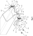
- Fig.3 shown partial exploded view of the bearing device designed for tensile load 10.
- the Fig.3 shows an exploded view of the side of the bearing device 10, the elements and components of which can be identified in the figures and also below with the suffix "a" in the reference number.
- the parts and components of the other side of the bearing device 10 that are not shown in the exploded view, which can also be identified in the figures and the following description with the suffix "b" in the reference number, are preferably designed analogously to the components described in detail below. The description is therefore only given in detail for one side.
- the bearing device 10 can have a cover 15, which can be designed as a sheet metal element or plastic element and covers the components of the bearing device 10 described below.
- the bearing plate 11a which on the one hand has holes for the fastening means BF and a centering pin ST1, so that a detachable fastening of the bearing plate and the cover 15 to the end section 102 of the support arm holder can be carried out by means of a screw connection.
- the two tension springs 71 which can be detachably connected to the bearing plate by means of screws S3 and S4 and which also connect a bearing axis holder 13a to the holder section 14a.
- the bearing plate 11a is preferably filled in an angular shape in order to save material and weight on the one hand and to ensure that a section of the angular shape in which the guide 12a is arranged can hold the bearing axis 50 perpendicular to the longitudinal axis of the support arm holder on the other.
- the end section 50a of the bearing axis 50 has, as shown, a threaded hole GB into which the adjusting element 80, which in this case can be a pin or threaded pin, can be inserted or screwed.
- the other side 50b also has a threaded hole GB (not shown) into which an adjusting element 80 can also be inserted.
- the bearing shaft 50 has a threaded portion on which the rolling element 90 is arranged, as shown on the assembled side or the side not shown in the exploded view of the Fig.3 is shown.
- a shifting or slipping of the rolling element 90 in the longitudinal direction can optionally be prevented by means of a pin ST2 or ST3.
- This pin can be a plug-in or threaded pin.
- the end section 50a or 50b on the other side of the longitudinal axis 50 is arranged in the assembled state within the guide section 12a or 12b of the bearing plate 11a or 11b, so that the longitudinal axis 50 is movably mounted along the recess of the guide 12a or 12b.
- the mobility of the longitudinal axis 50 relative to the guide 12 is made possible, among other things, as follows:
- the receiving section 14 encloses the end section 50a or 50b of the bearing axis 50, wherein the end sections 50a or 50b are pushed or inserted into the annular receiving section 14 and these receiving sections 14 are part of the bearing axis receptacle 13a or 13b, which are held by the tension springs 71.
- the tension springs 71 are connected to the bearing plate 11 by means of the screws S1-S4 and thus a deflection of the tension springs 71 causes the bearing axis 50 to move along the guides 12a, b.
- a force is exerted in the radial direction and in particular perpendicular to the longitudinal axis of the bearing axis 50, the tension springs 71 are guided and a movement of the longitudinal axis takes place along the guides 12a or 12b
- the movement can preferably be limited by means of a limit 16a, b, which can be arranged as a projection or taper within the guide 12a, fb.
- the limit 16 thus offers a defined end point for the (relative) movement of the bearing axis 50.
- the tension springs 71 hold the bearing axis 50 in the basic or reference position, in which there is no (large-area) contact between the lower wall of the support arm holder 110 and an outer wall or outer surface of the extension. This enables a smooth telescopic function or extendability or retractability of the extension (not shown).
- the Fig.4 a bearing device 1 designed for a compressive load, wherein the Fig.4 one in the unloaded state.
- the Fig.5 then further shows an exploded view of the bearing device 1 according to Fig.4 .
- the Fig.4 an end section 101 of a central extension 120 (shown in section), at the end of which an extension-side bearing connection section 121 is provided integrally, said section having a recess 122 in the corner region of the end section 101 and a substantially cross-shaped section 123 protruding in the region of the recess 122, said section having wing elements 123a and 123b.
- the function of the shape of the cross-shaped section 123 is explained in connection with the Fig.5 be explained in more detail.
- Fig.4 in this exemplary representation, two spring elements 70, which in this example are pressure-loadable springs or spiral springs, as well as preload elements 2, which are each arranged on one end side of the spring elements 70 in order to be able to adjust the preload of the spring elements 70 by means of the height of the preload elements 2.
- the preload elements 2 are ideally standard components, such as washers, with different heights.
- the spring elements 70 are supported on the sides of the preload elements 2, as in Fig.4 shown, against a cross member 3, the imaginary longitudinal axis of which is arranged parallel and spaced from the imaginary longitudinal axis of the bearing axis 50.
- bearing element 4a or 4b which can be plugged into the cross member 3, for example by means of a recess 7 within the bearing elements 4a or 4b.
- Another type of connection as well as a permanent material connection between the bearing elements 4 and the cross member 3 is also covered by the disclosure.
- the bearing elements 4a and 4b are, as shown in the Fig.4 shown, perpendicular to the imaginary longitudinal axis of the traverse element 3 and have guide receptacles 5a and 5b at an end region opposite the traverse element 3, which can preferably each accommodate an end section 50a or 50b of the bearing axis 50 with a precise fit or with little play.
- the longitudinal extension of the guide receptacles 5a and 5b in the direction of the traverse element is preferably set up in such a way that a predefined maximum deflection of the bearing axis 50 is set or defined when the bearing axis 50 is subjected to pressure.
- the guide receptacles 5a and 5b can, for example, be U-shaped recesses within the bearing elements 4a and 4b.
- Fig.4 visible adjustment elements 80 are preferably plug screws, threaded pins or the like.
- a reference or basic position of the bearing axis 50 can be set. This basic or reference position of the bearing axis 50 is preferably set such that when the corresponding extension (here the central extension 120) is assembled, the rolling elements 90 are arranged with their outer surface at a predefined distance above the upper outer surface of the central extension 120.
- the Fig.5 now shows further details of the above-described bearing device 1 and in particular shows the adjustment means 80 in the exploded view, which are designed as screws or threaded pins and, as can be seen in the exploded view using the dashed-dot lines, are inserted through holes within the cross member 3, through the washers 2, along the virtual longitudinal axis of the spring elements 70 into the holes B1 and B2 of the bearing axis 50. Furthermore, the Fig.5 It is also clear that a coupling section 8 is arranged on both sides of the traverse element 3, which can be connected with a substantially U-shaped basic shape to the wing elements 123b of the cross-shaped section 123 of the central extension 120.
- a second traverse element 3a in addition to the first traverse element 3, there is also a second traverse element 3a, as shown in the Fig.5 which also has an end-side coupling section 8a which can be connected in a form-fitting manner to the wing elements 123a of the central extension 120.
- the second traverse element 3a can be connected by means of a screw connection comprising, for example, screws 9a, washers and spacers 9c and 9b as well as lock nuts 9d can be connected to the first traverse element 3 in such a way that the cross-shaped section 123 of the central extension 120 can be connected in a force-fitting manner.
- the Fig. 6a and 6b now show, by way of example, a support arm with a central extension 120, which is supported by means of a bearing device 1 and 10 designed for compressive and tensile loads.
- the bearing device 1 designed for compressive loads is arranged at an end section of the central extension 120 in such a way that the rolling elements 90 or the bearing axis 50 are in contact with an upper inner surface of the support arm holder 110, while a bearing device 10 designed for tensile loads is arranged at an end section of the support arm holder 110 in such a way that the bearing axis 50 or the rolling elements 90 are in contact with a lower outer surface of the central extension 120, as both the Fig. 6a as well as the Fig. 6b
- cut-outs are provided in the drawings of the Fig. 6a and 6b according to the Fig.1 intended.
- the two Fig. 6a and 6b also a center of gravity, which is shown with M as the center of mass, as well as bearing or support forces, which are marked with thick arrows and F.
- M the center of mass
- bearing or support forces which are marked with thick arrows and F.
- the support force FA is maximum and at most half the mass M (weight force) of the support arm 100.
- the reaction force which is shown with FRL2 in Fig. 6b is marked, however, can be a multiple of the mass of the support arm 100.
- the center of mass of the mass M can be located to the right of the bearing 10 or the bearing device 10, and the force marked FRL1 is equal to the sum of the force FL2 and the mass M.
- the inventors of the present disclosure have solved this in such a way that with a predefined load that is greater than the mass M of the support arm 100 by a predetermined amount, the bearing device 1, 10 settles mechanically because the forces of the spring elements 70, 71 are exceeded or they are stretched or subjected to pressure so that they give way and a force is built up between the pull-out wall surfaces that blocks the telescopic function.
- the predetermined amount can be less than one kilogram or, particularly preferably, a few kilograms, for example 1 to 10 kg or even more.
- the spring travel of the spring elements 70, 71 can be mechanically limited and the spring force can be greater than the maximum mass M and, ideally, can be adjusted. This is achieved in the best possible way by the previously described bearing devices 1, 10 and the optional features.
- the Fig. 7a to d and 8a to c then show further necessary considerations with regard to the design and dimensioning of the two bearing devices 1 and 10.
- the Fig. 7a to 7d show the bearing device 10 designed for tensile load.
- the Fig. 7b a partial section of the support arm 100 with partial representations of the support arm holder 100 in the cutout, the central extension 120, the end extension 130 and a part of the holder 140, wherein the bearing device 10 designed for tensile load is attached to the support arm holder 110 in an end area by means of the fastening means BF and the cladding 15 is shown partially broken away in order to show the components behind it of the bearing device 10 stressed or designed for tensile load. Further details are then shown in the Fig.
- a part of the adjusting means 80 which is screwed or arranged within a bore of the bearing axis 50, also becomes visible.
- Fig. 8a to 8d the adjustment of the bearing device 1 designed for pressure load, whereby the Fig. 8a once again the already mentioned in connection with the Fig.4 and the Fig.5 shown components of the storage device 1 and the Fig. 8b a part of the installation situation in the assembled state of the support arm 100.
- the Fig. 8c shows the effect of adjusting the reference position of the bearing axis 50 by means of the adjusting means 80 based on the distance Y, which is Fig. 8c between an upper inner wall of the support arm holder 110 and an upper outer wall of the central extension 120.
- an adjustment of the reference position of the longitudinal axis 50 also affects the distance Z that the Fig.
- both distances Z and Y should be large enough so that there is as little contact as possible between the aforementioned surfaces of the extensions or support arm holder in order to ensure smooth operation of the telescopic function. This can be done easily and without great effort by means of a fine adjustment of the adjustment elements 80.
- a bearing device 1, 10 and a telescopic support arm 100 with at least one such bearing device 1, 10 are described here.
- the use of at least one bearing device 1, 10 on a support arm 100 means that the telescopic function is smoother and easier to operate and at the same time it is possible to lock this function in order to ensure maximum operating safety.
Landscapes
- Life Sciences & Earth Sciences (AREA)
- Engineering & Computer Science (AREA)
- Geology (AREA)
- Mechanical Engineering (AREA)
- Structural Engineering (AREA)
- Support Of The Bearing (AREA)
Claims (17)
- Dispositif de palier (1 ; 10) pour un bras de support (100) d'un dispositif de levage de véhicule automobile avec- un axe de palier (50) pour la mise en contact d'une section du bras de support (100) du dispositif de levage de véhicule automobile,- un dispositif de liaison (60) qui est conçu pour relier l'axe de palier (50) à une section du bras de support du dispositif de levage de véhicule automobile, et- un élément de ressort (70) qui est conçu pour supporter l'axe de palier (50) de manière mobile,caractérisé par un élément d'ajustement (80) qui est conçu de telle sorte qu'une position de référence relative entre l'axe de palier (50) et le dispositif de liaison (60) peut être modifiée au moyen d'un actionnement de l'élément d'ajustement (80).
- Dispositif de palier selon la revendication 1, caractérisé en ce que l'axe de palier (50) présente un alésage fileté (B1, B2) dans lequel l'élément d'ajustement (80) peut être disposé,
la position de référence relative entre l'axe de palier (50) et le dispositif de liaison (60) pouvant être réglée par un mouvement d'entrée ou de sortie de l'élément d'ajustement (80) dans ou hors de l'alésage fileté (51) de l'axe de palier (50). - Dispositif de palier selon au moins l'une quelconque des revendications précédentes, caractérisé en ce que l'axe de palier (50) présente une forme de base cylindrique et un élément de roulement annulaire (90) est disposé de manière à pouvoir tourner autour de l'axe de palier (50).
- Dispositif de palier selon au moins l'une quelconque des revendications précédentes, caractérisé par des éléments de précontrainte (2) qui sont conçus pour modifier une précontrainte de l'élément de ressort (70).
- Dispositif de palier selon au moins l'une quelconque des revendications précédentes, caractérisé en ce que le dispositif de palier (1 ; 10) est un dispositif de palier (1) conçu pour une charge de compression ou un dispositif de palier (10) conçu pour une charge de traction.
- Dispositif de palier selon la revendication 5, caractérisé en ce que le dispositif de liaison (60) du dispositif de palier (1) conçu pour une charge de compression présente un élément de traverse (3) sur lequel sont disposés à distance l'un de l'autre deux éléments de palier (4a, 4b) avec à chaque fois un logement de guidage (5a, 5b) et qui supportent de manière mobile un axe de palier (50) à distance de l'élément de traverse (3) dans une direction de déplacement,
l'au moins un élément de ressort (70) étant disposé entre l'élément de traverse (3) et l'axe de palier (50), lequel est comprimé lors d'un déplacement relatif de l'axe de palier (50) par rapport aux éléments de palier (4a, 4b). - Dispositif de palier selon la revendication 6, caractérisé en ce qu'au moins l'un élément d'ajustement (80) est connecté à l'axe de palier (50) de telle sorte qu'une distance (L1) entre l'axe de palier (50) et l'élément de traverse (3) puisse être réglée au moyen de l'élément d'ajustement (80).
- Dispositif de palier selon au moins l'une quelconque des revendications 6 à 7, caractérisé en ce que l'élément de traverse (3) présente une portion de liaison (121) qui est conçue pour établir une liaison amovible avec une portion d'extrémité (101) du bras de support (100) du dispositif de levage de véhicule automobile.
- Dispositif de palier selon au moins l'une quelconque des revendications 6 à 8, caractérisé en ce que des axes longitudinaux de l'élément de traverse (3) et de l'axe de palier (50) sont disposés parallèlement l'un à l'autre et un axe longitudinal de l'élément de ressort (70) et de l'élément d'ajustement (80) est disposé le long d'un plan de coupe des deux axes longitudinaux.
- Dispositif de palier selon au moins l'une quelconque des revendications 6 à 9, caractérisé en ce que l'élément de traverse (3) est réalisé en deux parties et un premier élément de traverse (3) peut être connecté aux éléments de palier (4a, 4b) et un deuxième élément de traverse (3a) est réalisé pour établir une liaison par engagement par correspondance de forme et/ou par force entre le premier élément de traverse (3a), une portion d'extrémité (101) du bras de support (100) et le deuxième élément de traverse (3b).
- Dispositif de palier selon la revendication 5, caractérisé en ce que le dispositif de liaison (60) du dispositif de palier (10) conçu pour une charge de traction présente un flasque de palier (11a, 11b) sur chaque portion d'extrémité (50a, 50b) de l'axe de palier (50), qui peut être connecté à chaque fois à une portion d'extrémité (102) du bras de support (100) du dispositif de levage de véhicule automobile, les flasques de palier (11a, 11b) présentant à chaque fois un guidage (12a, 12b) pour recevoir une portion d'extrémité (50a, 50b) de l'axe de palier (50), et l'élément de ressort étant disposé en tant qu'élément de ressort (71) sollicité en traction à chaque fois sur les flasques de palier (11a, 11b), qui peut être connecté à l'axe de palier (50).
- Dispositif de palier selon la revendication 11, caractérisé en ce que les portions d'extrémité (50a, 50b) de l'axe de palier (50) présentent à chaque fois un alésage fileté (51) et l'élément d'ajustement (80) peut être disposé dans celui-ci de telle sorte qu'une position relative entre l'axe de palier (50) et le flasque de palier (11a, 11b) puisse être réglée au moyen d'une modification de la position relative entre l'élément d'ajustement (80) et l'axe de palier (50).
- Dispositif de palier selon au moins l'une quelconque des revendications 11 à 12, caractérisé en ce qu'un logement d'axe de palier (13a, 13b) est disposé sur chaque flasque de palier (11a, 11b), lequel est maintenu au moyen de l'élément de ressort (71) et lequel présente une portion de réception (14) pour maintenir une portion d'extrémité de l'axe de palier (50).
- Bras de support pour un dispositif de levage de véhicule automobile comprenant un logement de bras de support (110), au moins un extracteur central (120) et un extracteur terminal (130), au moins un extracteur central étant disposé de manière déplaçable à l'intérieur du logement de bras de support (110) dans la direction longitudinale de celui-ci et l'extracteur terminal étant disposé de manière déplaçable dans un extracteur central dans la direction longitudinale de celui-ci, caractérisé en ce que le logement de bras de support (110) présente au niveau d'une portion d'extrémité un dispositif de palier selon au moins l'une quelconque des revendications 11 à 13 et l'extracteur central présente au moins un dispositif de palier selon au moins l'une quelconque des revendications 6 à 10.
- Bras de support pour un dispositif de levage de véhicule automobile comprenant un logement de bras de support (110) et un extracteur terminal (130), l'extracteur terminal (130) étant disposé de manière déplaçable à l'intérieur du logement de bras dans la direction longitudinale de celui-ci, caractérisé en ce que le logement de bras de support (110) présente au niveau d'une portion d'extrémité un dispositif de palier selon au moins l'une quelconque des revendications 11 à 13 et l'extracteur terminal (130) présente au moins un dispositif de palier selon au moins l'une quelconque des revendications 6 à 10.
- Bras de support selon la revendication 14, caractérisé en ce que le bras de support présente deux dispositifs de palier pour supporter un extracteur central, qui sont disposés de manière décalée l'un par rapport à l'autre par rapport à un axe longitudinal du bras de support, ou
le bras de support présente deux dispositifs de palier pour supporter l'extracteur terminal (130), qui sont disposés de manière décalée l'un par rapport à l'autre par rapport à un axe longitudinal du bras de support. - Bras de support selon la revendication 15, caractérisé en ce que le bras de support présente deux dispositifs de palier pour supporter l'extracteur terminal (130), qui sont disposés de manière décalée l'un par rapport à l'autre par rapport à un axe longitudinal du bras de support.
Applications Claiming Priority (1)
| Application Number | Priority Date | Filing Date | Title |
|---|---|---|---|
| DE102021204948.6A DE102021204948A1 (de) | 2021-05-17 | 2021-05-17 | Lagervorrichtung und tragarm einer kraftfahrzeug-hebevorrichtung |
Publications (2)
| Publication Number | Publication Date |
|---|---|
| EP4091982A1 EP4091982A1 (fr) | 2022-11-23 |
| EP4091982B1 true EP4091982B1 (fr) | 2024-07-24 |
Family
ID=81653570
Family Applications (1)
| Application Number | Title | Priority Date | Filing Date |
|---|---|---|---|
| EP22173351.2A Active EP4091982B1 (fr) | 2021-05-17 | 2022-05-13 | Dispositif palier et bras porteur d'un dispositif de levage de véhicule automobile |
Country Status (3)
| Country | Link |
|---|---|
| EP (1) | EP4091982B1 (fr) |
| DE (1) | DE102021204948A1 (fr) |
| ES (1) | ES2991785T3 (fr) |
Family Cites Families (4)
| Publication number | Priority date | Publication date | Assignee | Title |
|---|---|---|---|---|
| JP2002128481A (ja) * | 2000-10-20 | 2002-05-09 | Yasui:Kk | 車両整備用リフトの車体支持アーム |
| JP4358793B2 (ja) * | 2005-07-19 | 2009-11-04 | 株式会社スギヤス | リフト装置 |
| DE202006007156U1 (de) | 2006-05-04 | 2006-07-06 | Maha Maschinenbau Haldenwang Gmbh & Co. Kg | Tragarm für eine Hebebühne |
| AT505757B1 (de) | 2007-11-22 | 2009-04-15 | Miguel Muser | Manipulationsgerat zum be- und entladen eines regals |
-
2021
- 2021-05-17 DE DE102021204948.6A patent/DE102021204948A1/de not_active Withdrawn
-
2022
- 2022-05-13 EP EP22173351.2A patent/EP4091982B1/fr active Active
- 2022-05-13 ES ES22173351T patent/ES2991785T3/es active Active
Also Published As
| Publication number | Publication date |
|---|---|
| EP4091982A1 (fr) | 2022-11-23 |
| ES2991785T3 (es) | 2024-12-04 |
| DE102021204948A1 (de) | 2022-11-17 |
Similar Documents
| Publication | Publication Date | Title |
|---|---|---|
| EP3013729B1 (fr) | Dispositif pour soulever des véhicules | |
| EP2873344B1 (fr) | Meuble doté d'un pied réglable en hauteur | |
| EP4141282B1 (fr) | Frein à disque pour un véhicule automobile | |
| WO2009052907A1 (fr) | Poignée, anneau ou patère avec plaque de fixation et palier rotatif | |
| WO2005044046A1 (fr) | Mecanisme de retrait automatique destine a des guides de tiroirs | |
| DE102004038507A1 (de) | Rollenführung für verstellbare Fahrzeugsitze | |
| DE1503119A1 (de) | Bearbeitungsvorrichtung | |
| EP0789986A1 (fr) | Bielle de relevage pour accouplement à trois points de tracteur | |
| DE69107560T2 (de) | Arretiervorrichtung für einen Tragarm einer Kraftfahrzeughebebühne. | |
| DE102017214017A1 (de) | Vorrichtung zum Andrücken einer Zahnstange | |
| EP4091982B1 (fr) | Dispositif palier et bras porteur d'un dispositif de levage de véhicule automobile | |
| EP3681346B1 (fr) | Support de panneau et tiroir | |
| EP3461980B1 (fr) | Unité de déclenchement et pièce de meuble dotée d'une telle unité | |
| DE60003166T2 (de) | Kippvorrichtung | |
| EP2244925B1 (fr) | Colonne de direction réglable pour une automobile | |
| EP3819513B1 (fr) | Palier lisse, dispositif d'équipement pourvu d'au moins un palier lisse et dispositif d'équipement pourvu d'au moins un palier logé rotatif | |
| EP4058394B1 (fr) | Appareil de levage pour un ensemble d'un véhicule automobile, et procédé de fixation d'au moins un bras porteur d'un appareil de levage | |
| DE102023108833A1 (de) | Verriegelungsvorrichtung für Teleskopierzylinder | |
| DE102018100776A1 (de) | Hubsystem, Hängebahn mit einem Hubsystem sowie Fertigungs- und/oder Montageanlage mit einer Hängebahn | |
| DE3206550C1 (de) | Zeichenkopf fuer Zeichenmaschinen | |
| DE102021214325B4 (de) | Teleskopsäule für einen höhenverstellbaren Tisch und höhenverstellbarer Tisch mit einer solchen Teleskopsäule | |
| DE102023203647B4 (de) | Hydraulische Hubsäule und medizinische Vorrichtung | |
| EP4479337B1 (fr) | Dispositif de verrouillage pour cylindre télescopique | |
| EP2522557B1 (fr) | Dispositif d'appui pour véhicules utilitaires et procédé de fabrication d'un dispositif d'appui pour véhicules utilitaires | |
| DE20015380U1 (de) | Höhenverstellbare Auflage |
Legal Events
| Date | Code | Title | Description |
|---|---|---|---|
| PUAI | Public reference made under article 153(3) epc to a published international application that has entered the european phase |
Free format text: ORIGINAL CODE: 0009012 |
|
| STAA | Information on the status of an ep patent application or granted ep patent |
Free format text: STATUS: THE APPLICATION HAS BEEN PUBLISHED |
|
| AK | Designated contracting states |
Kind code of ref document: A1 Designated state(s): AL AT BE BG CH CY CZ DE DK EE ES FI FR GB GR HR HU IE IS IT LI LT LU LV MC MK MT NL NO PL PT RO RS SE SI SK SM TR |
|
| STAA | Information on the status of an ep patent application or granted ep patent |
Free format text: STATUS: REQUEST FOR EXAMINATION WAS MADE |
|
| 17P | Request for examination filed |
Effective date: 20230523 |
|
| RBV | Designated contracting states (corrected) |
Designated state(s): AL AT BE BG CH CY CZ DE DK EE ES FI FR GB GR HR HU IE IS IT LI LT LU LV MC MK MT NL NO PL PT RO RS SE SI SK SM TR |
|
| GRAP | Despatch of communication of intention to grant a patent |
Free format text: ORIGINAL CODE: EPIDOSNIGR1 |
|
| STAA | Information on the status of an ep patent application or granted ep patent |
Free format text: STATUS: GRANT OF PATENT IS INTENDED |
|
| INTG | Intention to grant announced |
Effective date: 20240314 |
|
| GRAS | Grant fee paid |
Free format text: ORIGINAL CODE: EPIDOSNIGR3 |
|
| GRAA | (expected) grant |
Free format text: ORIGINAL CODE: 0009210 |
|
| STAA | Information on the status of an ep patent application or granted ep patent |
Free format text: STATUS: THE PATENT HAS BEEN GRANTED |
|
| AK | Designated contracting states |
Kind code of ref document: B1 Designated state(s): AL AT BE BG CH CY CZ DE DK EE ES FI FR GB GR HR HU IE IS IT LI LT LU LV MC MK MT NL NO PL PT RO RS SE SI SK SM TR |
|
| REG | Reference to a national code |
Ref country code: GB Ref legal event code: FG4D Free format text: NOT ENGLISH |
|
| REG | Reference to a national code |
Ref country code: CH Ref legal event code: EP |
|
| REG | Reference to a national code |
Ref country code: IE Ref legal event code: FG4D Free format text: LANGUAGE OF EP DOCUMENT: GERMAN Ref country code: DE Ref legal event code: R096 Ref document number: 502022001281 Country of ref document: DE |
|
| REG | Reference to a national code |
Ref country code: NL Ref legal event code: FP |
|
| REG | Reference to a national code |
Ref country code: LT Ref legal event code: MG9D |
|
| REG | Reference to a national code |
Ref country code: ES Ref legal event code: FG2A Ref document number: 2991785 Country of ref document: ES Kind code of ref document: T3 Effective date: 20241204 |
|
| PG25 | Lapsed in a contracting state [announced via postgrant information from national office to epo] |
Ref country code: PT Free format text: LAPSE BECAUSE OF FAILURE TO SUBMIT A TRANSLATION OF THE DESCRIPTION OR TO PAY THE FEE WITHIN THE PRESCRIBED TIME-LIMIT Effective date: 20241125 |
|
| PG25 | Lapsed in a contracting state [announced via postgrant information from national office to epo] |
Ref country code: PT Free format text: LAPSE BECAUSE OF FAILURE TO SUBMIT A TRANSLATION OF THE DESCRIPTION OR TO PAY THE FEE WITHIN THE PRESCRIBED TIME-LIMIT Effective date: 20241125 |
|
| PG25 | Lapsed in a contracting state [announced via postgrant information from national office to epo] |
Ref country code: NO Free format text: LAPSE BECAUSE OF FAILURE TO SUBMIT A TRANSLATION OF THE DESCRIPTION OR TO PAY THE FEE WITHIN THE PRESCRIBED TIME-LIMIT Effective date: 20241024 |
|
| PG25 | Lapsed in a contracting state [announced via postgrant information from national office to epo] |
Ref country code: PL Free format text: LAPSE BECAUSE OF FAILURE TO SUBMIT A TRANSLATION OF THE DESCRIPTION OR TO PAY THE FEE WITHIN THE PRESCRIBED TIME-LIMIT Effective date: 20240724 Ref country code: GR Free format text: LAPSE BECAUSE OF FAILURE TO SUBMIT A TRANSLATION OF THE DESCRIPTION OR TO PAY THE FEE WITHIN THE PRESCRIBED TIME-LIMIT Effective date: 20241025 Ref country code: FI Free format text: LAPSE BECAUSE OF FAILURE TO SUBMIT A TRANSLATION OF THE DESCRIPTION OR TO PAY THE FEE WITHIN THE PRESCRIBED TIME-LIMIT Effective date: 20240724 |
|
| PG25 | Lapsed in a contracting state [announced via postgrant information from national office to epo] |
Ref country code: BG Free format text: LAPSE BECAUSE OF FAILURE TO SUBMIT A TRANSLATION OF THE DESCRIPTION OR TO PAY THE FEE WITHIN THE PRESCRIBED TIME-LIMIT Effective date: 20240724 |
|
| PG25 | Lapsed in a contracting state [announced via postgrant information from national office to epo] |
Ref country code: LV Free format text: LAPSE BECAUSE OF FAILURE TO SUBMIT A TRANSLATION OF THE DESCRIPTION OR TO PAY THE FEE WITHIN THE PRESCRIBED TIME-LIMIT Effective date: 20240724 |
|
| PG25 | Lapsed in a contracting state [announced via postgrant information from national office to epo] |
Ref country code: IS Free format text: LAPSE BECAUSE OF FAILURE TO SUBMIT A TRANSLATION OF THE DESCRIPTION OR TO PAY THE FEE WITHIN THE PRESCRIBED TIME-LIMIT Effective date: 20241124 |
|
| PG25 | Lapsed in a contracting state [announced via postgrant information from national office to epo] |
Ref country code: HR Free format text: LAPSE BECAUSE OF FAILURE TO SUBMIT A TRANSLATION OF THE DESCRIPTION OR TO PAY THE FEE WITHIN THE PRESCRIBED TIME-LIMIT Effective date: 20240724 |
|
| PG25 | Lapsed in a contracting state [announced via postgrant information from national office to epo] |
Ref country code: RS Free format text: LAPSE BECAUSE OF FAILURE TO SUBMIT A TRANSLATION OF THE DESCRIPTION OR TO PAY THE FEE WITHIN THE PRESCRIBED TIME-LIMIT Effective date: 20241024 |
|
| PG25 | Lapsed in a contracting state [announced via postgrant information from national office to epo] |
Ref country code: RS Free format text: LAPSE BECAUSE OF FAILURE TO SUBMIT A TRANSLATION OF THE DESCRIPTION OR TO PAY THE FEE WITHIN THE PRESCRIBED TIME-LIMIT Effective date: 20241024 Ref country code: PL Free format text: LAPSE BECAUSE OF FAILURE TO SUBMIT A TRANSLATION OF THE DESCRIPTION OR TO PAY THE FEE WITHIN THE PRESCRIBED TIME-LIMIT Effective date: 20240724 Ref country code: NO Free format text: LAPSE BECAUSE OF FAILURE TO SUBMIT A TRANSLATION OF THE DESCRIPTION OR TO PAY THE FEE WITHIN THE PRESCRIBED TIME-LIMIT Effective date: 20241024 Ref country code: LV Free format text: LAPSE BECAUSE OF FAILURE TO SUBMIT A TRANSLATION OF THE DESCRIPTION OR TO PAY THE FEE WITHIN THE PRESCRIBED TIME-LIMIT Effective date: 20240724 Ref country code: IS Free format text: LAPSE BECAUSE OF FAILURE TO SUBMIT A TRANSLATION OF THE DESCRIPTION OR TO PAY THE FEE WITHIN THE PRESCRIBED TIME-LIMIT Effective date: 20241124 Ref country code: HR Free format text: LAPSE BECAUSE OF FAILURE TO SUBMIT A TRANSLATION OF THE DESCRIPTION OR TO PAY THE FEE WITHIN THE PRESCRIBED TIME-LIMIT Effective date: 20240724 Ref country code: GR Free format text: LAPSE BECAUSE OF FAILURE TO SUBMIT A TRANSLATION OF THE DESCRIPTION OR TO PAY THE FEE WITHIN THE PRESCRIBED TIME-LIMIT Effective date: 20241025 Ref country code: FI Free format text: LAPSE BECAUSE OF FAILURE TO SUBMIT A TRANSLATION OF THE DESCRIPTION OR TO PAY THE FEE WITHIN THE PRESCRIBED TIME-LIMIT Effective date: 20240724 Ref country code: BG Free format text: LAPSE BECAUSE OF FAILURE TO SUBMIT A TRANSLATION OF THE DESCRIPTION OR TO PAY THE FEE WITHIN THE PRESCRIBED TIME-LIMIT Effective date: 20240724 |
|
| PG25 | Lapsed in a contracting state [announced via postgrant information from national office to epo] |
Ref country code: RO Free format text: LAPSE BECAUSE OF FAILURE TO SUBMIT A TRANSLATION OF THE DESCRIPTION OR TO PAY THE FEE WITHIN THE PRESCRIBED TIME-LIMIT Effective date: 20240724 Ref country code: SM Free format text: LAPSE BECAUSE OF FAILURE TO SUBMIT A TRANSLATION OF THE DESCRIPTION OR TO PAY THE FEE WITHIN THE PRESCRIBED TIME-LIMIT Effective date: 20240724 Ref country code: DK Free format text: LAPSE BECAUSE OF FAILURE TO SUBMIT A TRANSLATION OF THE DESCRIPTION OR TO PAY THE FEE WITHIN THE PRESCRIBED TIME-LIMIT Effective date: 20240724 |
|
| PG25 | Lapsed in a contracting state [announced via postgrant information from national office to epo] |
Ref country code: EE Free format text: LAPSE BECAUSE OF FAILURE TO SUBMIT A TRANSLATION OF THE DESCRIPTION OR TO PAY THE FEE WITHIN THE PRESCRIBED TIME-LIMIT Effective date: 20240724 |
|
| PG25 | Lapsed in a contracting state [announced via postgrant information from national office to epo] |
Ref country code: CZ Free format text: LAPSE BECAUSE OF FAILURE TO SUBMIT A TRANSLATION OF THE DESCRIPTION OR TO PAY THE FEE WITHIN THE PRESCRIBED TIME-LIMIT Effective date: 20240724 |
|
| REG | Reference to a national code |
Ref country code: DE Ref legal event code: R097 Ref document number: 502022001281 Country of ref document: DE |
|
| PG25 | Lapsed in a contracting state [announced via postgrant information from national office to epo] |
Ref country code: IT Free format text: LAPSE BECAUSE OF FAILURE TO SUBMIT A TRANSLATION OF THE DESCRIPTION OR TO PAY THE FEE WITHIN THE PRESCRIBED TIME-LIMIT Effective date: 20240724 Ref country code: SK Free format text: LAPSE BECAUSE OF FAILURE TO SUBMIT A TRANSLATION OF THE DESCRIPTION OR TO PAY THE FEE WITHIN THE PRESCRIBED TIME-LIMIT Effective date: 20240724 |
|
| PLBE | No opposition filed within time limit |
Free format text: ORIGINAL CODE: 0009261 |
|
| STAA | Information on the status of an ep patent application or granted ep patent |
Free format text: STATUS: NO OPPOSITION FILED WITHIN TIME LIMIT |
|
| PGFP | Annual fee paid to national office [announced via postgrant information from national office to epo] |
Ref country code: NL Payment date: 20250522 Year of fee payment: 4 |
|
| 26N | No opposition filed |
Effective date: 20250425 |
|
| PGFP | Annual fee paid to national office [announced via postgrant information from national office to epo] |
Ref country code: DE Payment date: 20250531 Year of fee payment: 4 |
|
| PGFP | Annual fee paid to national office [announced via postgrant information from national office to epo] |
Ref country code: ES Payment date: 20250616 Year of fee payment: 4 |
|
| PGFP | Annual fee paid to national office [announced via postgrant information from national office to epo] |
Ref country code: FR Payment date: 20250523 Year of fee payment: 4 |
|
| PGFP | Annual fee paid to national office [announced via postgrant information from national office to epo] |
Ref country code: AT Payment date: 20250721 Year of fee payment: 4 |
|
| PG25 | Lapsed in a contracting state [announced via postgrant information from national office to epo] |
Ref country code: SE Free format text: LAPSE BECAUSE OF FAILURE TO SUBMIT A TRANSLATION OF THE DESCRIPTION OR TO PAY THE FEE WITHIN THE PRESCRIBED TIME-LIMIT Effective date: 20240724 |
|
| REG | Reference to a national code |
Ref country code: CH Ref legal event code: H13 Free format text: ST27 STATUS EVENT CODE: U-0-0-H10-H13 (AS PROVIDED BY THE NATIONAL OFFICE) Effective date: 20251223 |
|
| PG25 | Lapsed in a contracting state [announced via postgrant information from national office to epo] |
Ref country code: LU Free format text: LAPSE BECAUSE OF NON-PAYMENT OF DUE FEES Effective date: 20250513 |
|
| PG25 | Lapsed in a contracting state [announced via postgrant information from national office to epo] |
Ref country code: CH Free format text: LAPSE BECAUSE OF NON-PAYMENT OF DUE FEES Effective date: 20250531 |
|
| REG | Reference to a national code |
Ref country code: BE Ref legal event code: MM Effective date: 20250531 |
|
| PG25 | Lapsed in a contracting state [announced via postgrant information from national office to epo] |
Ref country code: MC Free format text: LAPSE BECAUSE OF FAILURE TO SUBMIT A TRANSLATION OF THE DESCRIPTION OR TO PAY THE FEE WITHIN THE PRESCRIBED TIME-LIMIT Effective date: 20240724 |
|
| PG25 | Lapsed in a contracting state [announced via postgrant information from national office to epo] |
Ref country code: IE Free format text: LAPSE BECAUSE OF NON-PAYMENT OF DUE FEES Effective date: 20250513 |
|
| PG25 | Lapsed in a contracting state [announced via postgrant information from national office to epo] |
Ref country code: BE Free format text: LAPSE BECAUSE OF NON-PAYMENT OF DUE FEES Effective date: 20250531 |