EP4092164A1 - Appareil sous pression doté d'un dispositif structural de support - Google Patents
Appareil sous pression doté d'un dispositif structural de support Download PDFInfo
- Publication number
- EP4092164A1 EP4092164A1 EP21174032.9A EP21174032A EP4092164A1 EP 4092164 A1 EP4092164 A1 EP 4092164A1 EP 21174032 A EP21174032 A EP 21174032A EP 4092164 A1 EP4092164 A1 EP 4092164A1
- Authority
- EP
- European Patent Office
- Prior art keywords
- plastic component
- printing device
- metal
- metal unit
- metal plate
- Prior art date
- Legal status (The legal status is an assumption and is not a legal conclusion. Google has not performed a legal analysis and makes no representation as to the accuracy of the status listed.)
- Withdrawn
Links
- 229910052751 metal Inorganic materials 0.000 claims abstract description 132
- 239000002184 metal Substances 0.000 claims abstract description 132
- 239000004033 plastic Substances 0.000 claims abstract description 111
- 229920003023 plastic Polymers 0.000 claims abstract description 111
- 238000007639 printing Methods 0.000 claims abstract description 50
- OKTJSMMVPCPJKN-UHFFFAOYSA-N Carbon Chemical compound [C] OKTJSMMVPCPJKN-UHFFFAOYSA-N 0.000 claims description 2
- 229910000831 Steel Inorganic materials 0.000 claims description 2
- 229910052799 carbon Inorganic materials 0.000 claims description 2
- 239000002991 molded plastic Substances 0.000 claims description 2
- 229910001220 stainless steel Inorganic materials 0.000 claims description 2
- 239000010935 stainless steel Substances 0.000 claims description 2
- 239000010959 steel Substances 0.000 claims description 2
- 229920002430 Fibre-reinforced plastic Polymers 0.000 claims 1
- 239000003365 glass fiber Substances 0.000 claims 1
- 239000000446 fuel Substances 0.000 description 13
- 239000011324 bead Substances 0.000 description 12
- 238000010276 construction Methods 0.000 description 7
- 238000005868 electrolysis reaction Methods 0.000 description 7
- 239000001257 hydrogen Substances 0.000 description 7
- 229910052739 hydrogen Inorganic materials 0.000 description 7
- 238000004519 manufacturing process Methods 0.000 description 7
- UFHFLCQGNIYNRP-UHFFFAOYSA-N Hydrogen Chemical compound [H][H] UFHFLCQGNIYNRP-UHFFFAOYSA-N 0.000 description 6
- 238000010292 electrical insulation Methods 0.000 description 4
- HEMHJVSKTPXQMS-UHFFFAOYSA-M Sodium hydroxide Chemical compound [OH-].[Na+] HEMHJVSKTPXQMS-UHFFFAOYSA-M 0.000 description 3
- 229910052782 aluminium Inorganic materials 0.000 description 2
- XAGFODPZIPBFFR-UHFFFAOYSA-N aluminium Chemical compound [Al] XAGFODPZIPBFFR-UHFFFAOYSA-N 0.000 description 2
- QVGXLLKOCUKJST-UHFFFAOYSA-N atomic oxygen Chemical compound [O] QVGXLLKOCUKJST-UHFFFAOYSA-N 0.000 description 2
- 238000001311 chemical methods and process Methods 0.000 description 2
- 238000005516 engineering process Methods 0.000 description 2
- 239000007789 gas Substances 0.000 description 2
- 239000012528 membrane Substances 0.000 description 2
- 239000001301 oxygen Substances 0.000 description 2
- 229910052760 oxygen Inorganic materials 0.000 description 2
- 238000003860 storage Methods 0.000 description 2
- ZAMOUSCENKQFHK-UHFFFAOYSA-N Chlorine atom Chemical compound [Cl] ZAMOUSCENKQFHK-UHFFFAOYSA-N 0.000 description 1
- RYGMFSIKBFXOCR-UHFFFAOYSA-N Copper Chemical compound [Cu] RYGMFSIKBFXOCR-UHFFFAOYSA-N 0.000 description 1
- 239000004918 carbon fiber reinforced polymer Substances 0.000 description 1
- 238000006243 chemical reaction Methods 0.000 description 1
- 239000000460 chlorine Substances 0.000 description 1
- 229910052801 chlorine Inorganic materials 0.000 description 1
- 229910052802 copper Inorganic materials 0.000 description 1
- 239000010949 copper Substances 0.000 description 1
- 230000001419 dependent effect Effects 0.000 description 1
- 230000000694 effects Effects 0.000 description 1
- 230000005611 electricity Effects 0.000 description 1
- 238000004049 embossing Methods 0.000 description 1
- 239000011152 fibreglass Substances 0.000 description 1
- 150000002431 hydrogen Chemical class 0.000 description 1
- 238000007373 indentation Methods 0.000 description 1
- 238000002347 injection Methods 0.000 description 1
- 239000007924 injection Substances 0.000 description 1
- 239000000463 material Substances 0.000 description 1
- 150000002739 metals Chemical class 0.000 description 1
- 230000008092 positive effect Effects 0.000 description 1
- 230000002265 prevention Effects 0.000 description 1
- 238000006479 redox reaction Methods 0.000 description 1
- 235000011121 sodium hydroxide Nutrition 0.000 description 1
- 230000000087 stabilizing effect Effects 0.000 description 1
- 239000000126 substance Substances 0.000 description 1
- 230000007704 transition Effects 0.000 description 1
- XLYOFNOQVPJJNP-UHFFFAOYSA-N water Substances O XLYOFNOQVPJJNP-UHFFFAOYSA-N 0.000 description 1
Images

Classifications
-
- C—CHEMISTRY; METALLURGY
- C25—ELECTROLYTIC OR ELECTROPHORETIC PROCESSES; APPARATUS THEREFOR
- C25B—ELECTROLYTIC OR ELECTROPHORETIC PROCESSES FOR THE PRODUCTION OF COMPOUNDS OR NON-METALS; APPARATUS THEREFOR
- C25B9/00—Cells or assemblies of cells; Constructional parts of cells; Assemblies of constructional parts, e.g. electrode-diaphragm assemblies; Process-related cell features
- C25B9/05—Pressure cells
-
- C—CHEMISTRY; METALLURGY
- C25—ELECTROLYTIC OR ELECTROPHORETIC PROCESSES; APPARATUS THEREFOR
- C25B—ELECTROLYTIC OR ELECTROPHORETIC PROCESSES FOR THE PRODUCTION OF COMPOUNDS OR NON-METALS; APPARATUS THEREFOR
- C25B9/00—Cells or assemblies of cells; Constructional parts of cells; Assemblies of constructional parts, e.g. electrode-diaphragm assemblies; Process-related cell features
- C25B9/60—Constructional parts of cells
-
- H—ELECTRICITY
- H01—ELECTRIC ELEMENTS
- H01M—PROCESSES OR MEANS, e.g. BATTERIES, FOR THE DIRECT CONVERSION OF CHEMICAL ENERGY INTO ELECTRICAL ENERGY
- H01M8/00—Fuel cells; Manufacture thereof
- H01M8/02—Details
- H01M8/0202—Collectors; Separators, e.g. bipolar separators; Interconnectors
- H01M8/0204—Non-porous and characterised by the material
- H01M8/0223—Composites
- H01M8/0228—Composites in the form of layered or coated products
-
- Y—GENERAL TAGGING OF NEW TECHNOLOGICAL DEVELOPMENTS; GENERAL TAGGING OF CROSS-SECTIONAL TECHNOLOGIES SPANNING OVER SEVERAL SECTIONS OF THE IPC; TECHNICAL SUBJECTS COVERED BY FORMER USPC CROSS-REFERENCE ART COLLECTIONS [XRACs] AND DIGESTS
- Y02—TECHNOLOGIES OR APPLICATIONS FOR MITIGATION OR ADAPTATION AGAINST CLIMATE CHANGE
- Y02E—REDUCTION OF GREENHOUSE GAS [GHG] EMISSIONS, RELATED TO ENERGY GENERATION, TRANSMISSION OR DISTRIBUTION
- Y02E60/00—Enabling technologies; Technologies with a potential or indirect contribution to GHG emissions mitigation
- Y02E60/30—Hydrogen technology
- Y02E60/50—Fuel cells
Definitions
- the invention relates to a printing device, in particular an electrochemical cell with a support structure device.
- pressure equipment is defined by the Pressure Equipment Directive. This is generally used to mean products that are under pressure.
- the term pressure equipment results from the associated English term "pressure equipment”.
- Pressure Equipment Directive the following products, among others, are considered to be pressure equipment: Vessels (unfired pressure vessels), steam boilers, pipelines, pressure-retaining accessories, safety accessories. In each case, there is an internal pressure of more than 0.5 bar.
- the term “printing device” does not refer to an ordinary printer that prints text on paper. Printers such as products from Canon, Hewlett Packard or Brother are therefore not printing devices within the meaning of this patent application.
- electrochemical cells such as fuel cells and/or electrolytic cells are addressed.
- pressure device preferably refers to the electrochemical cells mentioned.
- Pressure devices such as electrolytic cells, fuel cells, other galvanic cells or low-temperature heat exchangers should be as inexpensive as possible. At the same time, it is required that this pressure equipment can withstand the required loads without damage. In applications in which certain printing device components have flat dimensions, there is a need to produce the respective printing device even more cost-effectively. Especially at low pressures, complex metal components can be significantly more expensive than plastic, for example.
- the pressure devices often have to be able to withstand loads of 20, 50 or even more than 100 bar during operation. For this reason, such printing devices have, for example, metal struts or a metal-like framework, which gives these printing devices appropriate stability.
- pressure devices of correspondingly larger dimensions such as fuel cells, which are to be used for aircraft, correspondingly massive structural components are required in order to absorb the loads occurring during normal operation of the fuel cell. This need to absorb the loads or pressures or compressive forces that occur during operation represents both an obstacle and a cost factor. For this reason, there is a need to provide a stable pressure device that is easier to manufacture and can still absorb the necessary loads or these able to withstand operational loads.
- U.S. Patent 6,554,978 B1 relates to a high-pressure electrolyser.
- the high-pressure electrolyzer has a plurality of electrolytic chambers held in a frame. These electrolysis chambers are separated by a membrane. Electrodes are pressed against this membrane. Electrodes are electrically connected to a bipolar plate via a metal mesh. Even if a frame is mentioned in principle, which holds electrolysis chambers, this document does not show that the forces or loads occurring during normal operation of the high-pressure electrolyzer are absorbed by the frame.
- the US patent is silent on any component or structure that imparts stability to the high-pressure electrolyzer.
- An object of the invention can be seen as providing a stable printing device that is inexpensive and/or less complex.
- the invention provides a printing device with a support structure device for the printing device.
- the pressure device may be an electrochemical cell, a fuel cell, and/or an electrolytic cell.
- the support structure device includes a metal unit.
- the metal unit can be designed to be load-bearing.
- the metal unit can be implemented as a carrier component.
- the support structure device also has a plastic component which is arranged on the metal unit.
- the plastic component can be arranged directly on the metal unit.
- the metal unit and the plastic component are positively connected to one another at least in certain areas. The metal unit and the plastic component can thus be in direct contact with one another.
- the plastic component and the metal unit are designed to largely absorb a predetermined load on the printing device.
- the specified load can be, for example, a manufacturer's maximum allowable load for the printing device.
- the load can be force, pressure, tension and/or torsion.
- it can be specified for an electrolytic cell that a maximum pressure of 200 bar can occur or is permissible when the electrolytic cell is operated.
- the load or load allowed or intended by the manufacturer may also be given in the form of a force, tension or torsion.
- Form-fitting connections preferably result from the interlocking of at least two components.
- the two components are the metal unit and the plastic component.
- these two components can be preferred not separate from each other.
- the metal unit in particular is in the way of the plastic component, or vice versa.
- a positive connection represents in particular a prevention of a possible movement of one of these two components relative to the other.
- the form fit or the positive connection can be interpreted as a blockage.
- the metal unit can have an opening and the plastic component can have a pin projecting perpendicularly to a base body of the plastic component.
- This pin can be placed in the opening of the metal unit so that a form-fitting connection is established. Due to the pin of the plastic component, the positive connection can be realized in this example. In this case, the plastic component can no longer be moved independently of the metal unit.
- the plastic component can be implemented as a complex plastic component geometry. Although a rectangular or cuboid plastic component is often preferred, the plastic component can also assume complex structures or geometries.
- An important aspect of this invention is that the metal unit, together with the plastic component, bears most of the stresses encountered in the printing device by these two components. Ideally, only these two components, the plastic component and the metal unit, can absorb this load. Accordingly, a complex support structure, for example in the form of a metal framework omitted. As a result, the printing device can be implemented significantly more cost-effectively and less complex.
- Such fuel cells or electrolytic cells must be dimensioned in a correspondingly stable manner with a corresponding output.
- a fuel cell is to generate several kilowatts of power, correspondingly high loads, i.e. pressures, must be expected when the fuel cell is in operation. Therefore, such a fuel cell requires a correspondingly stable construction or a correspondingly stable framework. This is exactly where the invention comes into play.
- the invention provides that the metal unit and the plastic component can absorb most of such a load.
- the printing device can be designed in a correspondingly simpler manner, or the printing device can be manufactured significantly more cheaply.
- An additional or alternative embodiment provides that only the plastic component and the metal unit are set up to absorb at least 85 percent of the specified load on the printing device.
- the specified load is only absorbed by the plastic component and the metal unit, and this by at least 85 percent.
- the metal unit and plastic component can also take more than 85 percent of the load, so also 90, 95, 96, 97, 98, 99 and 100 percent.
- the specified load can be 200 bar, for example, with an appropriately dimensioned electrolytic cell. In this case, the manufacturer states, for example, that the electrolytic cell is approved for loads of up to 200 bar.
- This embodiment provides that only the plastic component and the metal unit can absorb at least 150 bar of this 200 bar maximum load.
- the metal unit and the plastic component can mean that through the metal unit and the plastic component, a corresponding force input or force dissipation is enabled. It is preferably provided that the plastic component and the metal unit withstand this load, ie the printing device can be operated non-destructively and/or maintenance-free. Additional parts or components for stabilizing or supporting the printing device are preferably not required. At best, they could still be provided to allay concerns, especially when the printing device is introduced.
- the metal unit can be designed as a flat metal plate and have an opening into which a first part of the plastic component is introduced in a form-fitting manner.
- a second part of the plastic component can be arranged directly on the metal plate.
- a first part of the plastic component can be regarded as the main part.
- This main part can be a cuboid, for example.
- the second part can protrude perpendicularly to this cuboid.
- This vertically protruding second part can be a pin, for example. This pin is preferably inserted into the opening of the metal plate or plugged into this opening.
- the first part of the plastic component preferably lies directly on the metal plate or is arranged on the metal plate.
- the plastic component can be T-shaped.
- the horizontal part would represent the first part, while the vertical part of the T-shaped plastic component represents the second part of the plastic component, specifically the spigot.
- the metal plate can be a carrier component in the form of a metal sheet.
- the metal unit is L-shaped, U-shaped, trough-shaped and/or Z-shaped and the plastic component with the Metal plate forms the positive connection.
- the metal unit can thus have an L profile, U profile, trough profile and/or Z profile. A combination of these possible shapes for the metal unit is also possible.
- the plastic component is preferably arranged in or on the metal unit in such a way that movement in at least one direction parallel to a base area of the metal unit or metal plate is prevented.
- the base of the metal unit is preferably a flat support surface on which the plastic component can be placed. With a U-shaped profile, the plastic component can be placed between the two protruding legs of the "U".
- the positive connection can be realized by direct contact of at least one leg of the U with the plastic component.
- two side surfaces of the plastic component can have direct contact with the U-profile.
- the metal unit is not just a flat metal plate, but has a corresponding deformation.
- part of the metal plate can be bent perpendicular to the base of the metal plate. If a corresponding force is applied to the plastic component, the force can be transferred or introduced via the deformation in the metal plate.
- the metal unit can have at least one elevation that is essentially perpendicular to a planar base area of the metal unit.
- the essentially vertical elevation can in particular include an angle of 75 to 110 degrees. This means that the elevation can have an angle of between 75, 80, 85, 90, 95, 100, 105 or 110 degrees with the flat base.
- the plastic component is arranged directly on the essentially vertical elevation. This means that the plastic component can be in contact with the vertical elevation of the metal unit.
- the form-fitting connection can be produced in particular by an acting pressure or the application of force.
- the metal unit can be designed as a metal plate and have a curvature in some areas or a recess in some areas perpendicular to the metal plate.
- a bulge is preferably spoken of when it is a rounded elevation.
- the curvature it is also possible for the curvature to be rectilinear and to be arranged essentially perpendicular to the base area. This would be more like an L-profile, for example.
- the plastic component can have a regional recess or curvature corresponding to the metal plate, and the plastic component is positively connected to the metal plate by the regional recess or curvature. This applies in particular in the event of a corresponding force or pressure being applied to the plastic component.
- the curvature or recess can be rounded. These bulges or recesses can also be viewed as a bead. Beads are, in particular, channel-shaped indentations. They are often used to stiffen thin-walled components against deformation or vibrations. Beads embossed into a plastically deformable material may be referred to as "embossing". Sharp-edged beads can be referred to as a fold. A recessed side of a bead may be referred to as a groove. A raised side of the bead is often referred to as a rib or ridge. The bead can mean a wavy elevation or recess of the metal plate or the plastic component.
- the curvature of the metal plate largely corresponds to the recess in the plastic component.
- these two components can interlock and thus enable a form-fitting connection. This applies in particular when there is a corresponding pressure or force effect on the plastic component.
- force can be transmitted to a bead in the metal plate and/or the plastic component.
- the previous examples describe different ways in which a form-fitting connection can be implemented.
- the form-fitting connection can be implemented using grooves or screws.
- the form-fitting connection can only be realized using the plastic component and the metal unit without further components.
- the plastic component and the metal unit can be arranged on one another in such a way that the form-fitting connection is realized when a corresponding pressure or force is applied to the metal plate or plastic component.
- the plastic component can be essentially rectangular or cuboid.
- the plastic component preferably has a type of saw geometry.
- a saw geometry is, in particular, a geometric shape that can be implemented using a saw, such as a circular saw, for example.
- the plastic component can be pyramid-shaped.
- the plastic component and the metal unit can be geometrically matched to one another in such a way that a plug-in connection between the plastic component and the metal unit is made possible.
- the positive connection between the plastic component and the metal unit can also be referred to as a hybrid component.
- With the help of rectangular or cuboid plastic components high loads or strong forces can be absorbed. A particularly stable fuel cell or a particularly stable pressure device can thus be created.
- the plastic component can be made of glass fiber reinforced plastic and/or injection molded plastic.
- the plastic component also has the advantage that electrical insulation is made possible. In this way, for example, several cells in an electrolytic cell or fuel cell can be electrically insulated from one another. When using injected plastic, simple manufacturing processes can be inexpensive will be realized. In this case, large quantities can be manufactured cheaply and efficiently.
- the metal unit can include stainless steel, sheet metal, steel and/or carbon.
- the metal unit can be designed as a carrier component for the plastic component.
- the sheet can be copper sheet or aluminum sheet. In this case the metal unit supports the plastic component.
- a hybrid design can thus be created which can absorb the high loads during operation of the printing device. Compressive forces applied to the plastic component or metal unit are redirected to the metal unit and carried by it, in particular due to the form fit that is realized.
- the printing device is designed as an electrolytic cell.
- Electrolysis is a term for a chemical process in which an electric current forces a redox reaction. It is preferably used to extract metals or to produce substances that would be more expensive or hardly possible to obtain using chemical processes. Examples of important electrolysis are the production of hydrogen, aluminum, chlorine and caustic soda.
- the pressure device can thus be used in the form of an electrolytic cell for the production of hydrogen.
- the present invention is preferably used in the context of a hydrogen electrolysis. In this case, water (H 2 O) is split into the two gases oxygen and hydrogen. This is done using energy. To put it simply, electrolysis can be viewed as a reverse oxyhydrogen reaction.
- excess electricity that is available from renewable energies can be used for electrolysis, i.e. the production of hydrogen.
- electrolysis i.e. the production of hydrogen.
- the electrolytic cells must be able to withstand the corresponding loads. This is where the invention comes in.
- the electrolytic cell can be made less complex, inexpensive, but still stable and robust.
- the plastic component and the metal component are set up to absorb a load of at least 30 bar.
- High-performance electrolytic cells produce corresponding hydrogen and oxygen gases. This can lead to increased pressures in certain cells in the electrolytic cell.
- the electrolytic cells can produce hydrogen at a pressure of 15 bar or more. Due to this overpressure, a corresponding force is applied inside the electrolytic cell, which must be compensated accordingly.
- the forces that occur are absorbed exclusively by the hybrid construction of the support structure device made of plastic component and metal unit.
- the advantages and examples already mentioned apply mutatis mutandis to different pressure devices.
- aspects and advantages of the aforementioned embodiments can be transferred to the electrolytic cell and/or fuel cell.
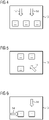
- a pressure device 10 with a load 14 acting in each case are shown.
- the load 14 can be realized in the form of pressure, force, tension and/or torsion.
- a plurality of support structure devices 11 are indicated within each of these printing devices 10 . As the 4, 5 and 6 1, the load 14 may be applied to the support structure devices 11 from different directions.
- the support structure device 11 contains in particular a plastic component 12 and a metal unit 13.
- the plastic component 12 can have several parts. So is in FIG 1 by way of example, a first part 12a of the plastic component 12 is indicated as a pin 12a. This pin 12a is inserted into an opening of the metal unit 13.
- the metal plate 13 is designed as a flat metal sheet.
- the flat metal plate 13 has a flat base 16 on which a large part of the plastic component 12 is arranged.
- a second part 12b of the plastic component 12 is preferably arranged directly on the base area 16 of the metal plate 13 .
- the pin 12a is preferably introduced into the corresponding opening of the metal plate 13 in a form-fitting manner.
- the load 14 can in particular be a predetermined maximum load.
- the specified maximum load can be specified by the manufacturer, for example. For example, it can indicate up to which load 14 of the support structure device 11 the printing device 10 is permitted.
- the load 14 can be, for example, 30, 40, 50 bar or even more.
- FIG 1 a continuation of the plastic component 12 is indicated above the plastic component 12 by dashed lines.
- the complex geometry of the plastic component can thus be viewed as a type of framework for the printing device 10 . Due to the pin 12a in the corresponding opening of the metal plate 13, a force is transferred to the metal unit 13 or directed there.
- FIG. 2 Another way of realizing a form-fitting connection between the plastic component 12 and the metal unit 13 is shown in FIG FIG 2 .
- the metal unit 13 is L-shaped.
- the plastic component 12 can be arranged directly on the base 16 of the metal plate 13 .
- the metal plate 13 has a second part 13b.
- This second part 13b of the metal plate 13 is perpendicular to the base 16 of the metal plate 13.
- the first part 13a of the metal plate 13 corresponds to the base 16 in the L-profile.
- the plastic component 12 is attached to a surface of the second part 13b of the L-shaped metal plate 13 is pressed.
- a form-fitting connection can thus be realized.
- the plastic component 12 can be attached to the metal unit 13 by means of screws or grooves.
- the plastic component 12 has a bulge 15 .
- the plastic component 12 has a recess 15 corresponding thereto.
- the curvature 15 of the metal plate 13 and the recess 15 of the plastic component 12 are ideally matched to one another so that these two components can form a form-fitting connection.
- the positive connection realized by the bulge 15 and recess 15 prevents a relative movement of these two components to one another.
- the action of force 14 can be caused by pressure.
- the bulge 15 and recess 15 can each be regarded as a bead.
- the bead 15 can be circular or round.
- the recess 15 tends to be angular and designed as a fold. In the case of a continuously round bulge, one would rather speak of a bead.
- the cost of complex metal components is significantly higher than for plastic, for example, which would result in a high cost increase here.
- the specific costs can be massively reduced through mass production.
- complex metal components that are milled or etched would mean a significantly higher financial outlay. This additional financial expense can be significantly reduced with the hybrid construction proposed here.
- this hybrid design can be used to implement this electrical insulation without additional components.
- Other electrolytic cells require additional components.
- Conventional pressure devices often also contain plastic components, but massive wall thicknesses are often required in order to achieve appropriate stability. With the aid of the hybrid design proposed here, the required stability or robustness of the printing device 10 can be achieved with simple carrier components in connection with the plastic component 12 .
- the metal unit 13 can be implemented as a simple carrier component such as a sheet metal or CFRP plate. Thanks to the hybrid construction of the support structure device 11, the printing device 10 presented here enables an improved construction with a significantly lower economic outlay. This advantage has a positive effect, particularly in the case of large quantities. At the same time, the plastic component 12 means that in many cases no additional components are required if electrical insulation is required.
Landscapes
- Chemical & Material Sciences (AREA)
- Engineering & Computer Science (AREA)
- Chemical Kinetics & Catalysis (AREA)
- Electrochemistry (AREA)
- Materials Engineering (AREA)
- Metallurgy (AREA)
- Organic Chemistry (AREA)
- Printing Plates And Materials Therefor (AREA)
Priority Applications (1)
| Application Number | Priority Date | Filing Date | Title |
|---|---|---|---|
| EP21174032.9A EP4092164A1 (fr) | 2021-05-17 | 2021-05-17 | Appareil sous pression doté d'un dispositif structural de support |
Applications Claiming Priority (1)
| Application Number | Priority Date | Filing Date | Title |
|---|---|---|---|
| EP21174032.9A EP4092164A1 (fr) | 2021-05-17 | 2021-05-17 | Appareil sous pression doté d'un dispositif structural de support |
Publications (1)
| Publication Number | Publication Date |
|---|---|
| EP4092164A1 true EP4092164A1 (fr) | 2022-11-23 |
Family
ID=75936839
Family Applications (1)
| Application Number | Title | Priority Date | Filing Date |
|---|---|---|---|
| EP21174032.9A Withdrawn EP4092164A1 (fr) | 2021-05-17 | 2021-05-17 | Appareil sous pression doté d'un dispositif structural de support |
Country Status (1)
| Country | Link |
|---|---|
| EP (1) | EP4092164A1 (fr) |
Citations (8)
| Publication number | Priority date | Publication date | Assignee | Title |
|---|---|---|---|---|
| US4746415A (en) * | 1985-12-16 | 1988-05-24 | Imperial Chemical Industries Plc | Electrode |
| US6554978B1 (en) | 1998-10-12 | 2003-04-29 | Vandenborre Technologies Nv | High pressure electrolyzer module |
| US20070251829A1 (en) * | 1999-11-24 | 2007-11-01 | Marsh Stephen A | Method and apparatus for electro-chemical reaction |
| US20080060937A1 (en) * | 2001-09-27 | 2008-03-13 | Proton Energy Systems Inc. | Apparatus and method for maintaining compression of the active area in an electrochemical cell |
| US8308917B2 (en) * | 2008-07-15 | 2012-11-13 | Next Hydrogen Corporation | Electrolyser module |
| WO2014072150A1 (fr) * | 2012-11-08 | 2014-05-15 | Siemens Aktiengesellschaft | Plaque bipolaire pour électrolyseur, électrolyseur et procédé de fabrication d'une plaque bipolaire |
| US20160160363A1 (en) * | 2013-07-17 | 2016-06-09 | Itm Power (Research) Limited | Composite hardware for an electrochemical cell |
| CN110220104A (zh) * | 2019-05-31 | 2019-09-10 | 亚普汽车部件股份有限公司 | 高压复合容器及其制造工艺 |
-
2021
- 2021-05-17 EP EP21174032.9A patent/EP4092164A1/fr not_active Withdrawn
Patent Citations (8)
| Publication number | Priority date | Publication date | Assignee | Title |
|---|---|---|---|---|
| US4746415A (en) * | 1985-12-16 | 1988-05-24 | Imperial Chemical Industries Plc | Electrode |
| US6554978B1 (en) | 1998-10-12 | 2003-04-29 | Vandenborre Technologies Nv | High pressure electrolyzer module |
| US20070251829A1 (en) * | 1999-11-24 | 2007-11-01 | Marsh Stephen A | Method and apparatus for electro-chemical reaction |
| US20080060937A1 (en) * | 2001-09-27 | 2008-03-13 | Proton Energy Systems Inc. | Apparatus and method for maintaining compression of the active area in an electrochemical cell |
| US8308917B2 (en) * | 2008-07-15 | 2012-11-13 | Next Hydrogen Corporation | Electrolyser module |
| WO2014072150A1 (fr) * | 2012-11-08 | 2014-05-15 | Siemens Aktiengesellschaft | Plaque bipolaire pour électrolyseur, électrolyseur et procédé de fabrication d'une plaque bipolaire |
| US20160160363A1 (en) * | 2013-07-17 | 2016-06-09 | Itm Power (Research) Limited | Composite hardware for an electrochemical cell |
| CN110220104A (zh) * | 2019-05-31 | 2019-09-10 | 亚普汽车部件股份有限公司 | 高压复合容器及其制造工艺 |
Similar Documents
| Publication | Publication Date | Title |
|---|---|---|
| DE102009019837B4 (de) | Kompressionsbeibehaltungssystem, Brennstoffzellensystem und Verfahren zum Zusammenbauen eines solchen | |
| DE102018102314B4 (de) | Matrizenanordnung für eine prägepresse | |
| DE112008000472B4 (de) | Brennstoffzelle und Befestigungsvorrichtung für eine Brennstoffzelle | |
| EP2065958A1 (fr) | Plaques bipolaires pour empilement de cellules combustibles | |
| EP1244167A1 (fr) | Plaques d'extremité pour une cellule électrochimque à membrane électrolytique en polymère | |
| DE102017213964A1 (de) | Separator für eine Brennstoffzelle und Elementarzelle einer Brennstoffzelle | |
| DE102014102504B4 (de) | Brennstoffzellensystem mit umgebördelter brennstoffzellenstapel-abdeckung und verfahren zum herstellen eines derartigen brennstoffzellensystems | |
| WO2023062088A2 (fr) | Cadre pour cellules électrochimiques et dispositifs de type à empilement | |
| DE112005002126T5 (de) | Ausrichtungsverfahren für sich wiederholende und nicht wiederholende Einheiten in einem Brennstoffzellenstapel | |
| DE102015219915A1 (de) | Vorrichtung zum Aktivieren eines Membranelektrodenaufbaus für Brennstoffzellen | |
| EP4112782A1 (fr) | Dispositif de montage, ainsi qu'utilisation du dispositif de montage pour le montage des cellules d'électrolyse d'un électrolyseur | |
| DE102019131088A1 (de) | Kernmatrize für Presse zum Formen eines Metallseparators für eine Brennstoffzelle für Brennstoffzellenfahrzeug | |
| DE112018000798T5 (de) | Blattfeder-kompressionssystemauslegung | |
| EP4218076B1 (fr) | Agencement de piles à combustible et procédé de fabrication d'un agencement de piles à combustible | |
| DE102018204753B4 (de) | Fahrzeugfrontstruktur | |
| DE102008052945B4 (de) | Brennstoffzellenstapel und Verfahren zu dessen Herstellung | |
| EP1589602B1 (fr) | Ressort de contact et pile eléctrique le contenant | |
| EP4092164A1 (fr) | Appareil sous pression doté d'un dispositif structural de support | |
| DE102007059449B4 (de) | Brennstoffzellensystem und Kompressionshalterungssystem mit planaren Streifen | |
| DE102013210545A1 (de) | Verfahren zur Montage eines Brennstoffzellenstapels sowie Positioniervorrichtung zur Durchführung des Verfahrens | |
| DE102020207918B4 (de) | Brennstoffzellenanordnung und Verfahren zur Herstellung einer Brennstoffzellenanordnung | |
| WO2013178536A1 (fr) | Plaque d'extrémité pour une pile à combustible et pile à combustible équipée d'une telle plaque | |
| WO2022122080A1 (fr) | Tôle formant électrode destinée à une batterie redox et batterie redox | |
| WO2010000355A1 (fr) | Dispositif de production d'un mélange d'oxygène et d'hydrogène | |
| DE102024208119A1 (de) | Elektrolyseur |
Legal Events
| Date | Code | Title | Description |
|---|---|---|---|
| PUAI | Public reference made under article 153(3) epc to a published international application that has entered the european phase |
Free format text: ORIGINAL CODE: 0009012 |
|
| STAA | Information on the status of an ep patent application or granted ep patent |
Free format text: STATUS: THE APPLICATION HAS BEEN PUBLISHED |
|
| AK | Designated contracting states |
Kind code of ref document: A1 Designated state(s): AL AT BE BG CH CY CZ DE DK EE ES FI FR GB GR HR HU IE IS IT LI LT LU LV MC MK MT NL NO PL PT RO RS SE SI SK SM TR |
|
| STAA | Information on the status of an ep patent application or granted ep patent |
Free format text: STATUS: THE APPLICATION IS DEEMED TO BE WITHDRAWN |
|
| 18D | Application deemed to be withdrawn |
Effective date: 20230524 |