EP4092231A1 - Dispositif de déverrouillage électromécanique à action rapide - Google Patents
Dispositif de déverrouillage électromécanique à action rapide Download PDFInfo
- Publication number
- EP4092231A1 EP4092231A1 EP22173441.1A EP22173441A EP4092231A1 EP 4092231 A1 EP4092231 A1 EP 4092231A1 EP 22173441 A EP22173441 A EP 22173441A EP 4092231 A1 EP4092231 A1 EP 4092231A1
- Authority
- EP
- European Patent Office
- Prior art keywords
- arming
- crank
- holding
- sear
- armature
- Prior art date
- Legal status (The legal status is an assumption and is not a legal conclusion. Google has not performed a legal analysis and makes no representation as to the accuracy of the status listed.)
- Granted
Links
Images


Classifications
-
- E—FIXED CONSTRUCTIONS
- E05—LOCKS; KEYS; WINDOW OR DOOR FITTINGS; SAFES
- E05B—LOCKS; ACCESSORIES THEREFOR; HANDCUFFS
- E05B47/00—Operating or controlling locks or other fastening devices by electric or magnetic means
- E05B47/0046—Electric or magnetic means in the striker or on the frame; Operating or controlling the striker plate
- E05B47/0047—Striker rotating about an axis parallel to the wing edge
-
- E—FIXED CONSTRUCTIONS
- E05—LOCKS; KEYS; WINDOW OR DOOR FITTINGS; SAFES
- E05B—LOCKS; ACCESSORIES THEREFOR; HANDCUFFS
- E05B47/00—Operating or controlling locks or other fastening devices by electric or magnetic means
- E05B47/0001—Operating or controlling locks or other fastening devices by electric or magnetic means with electric actuators; Constructional features thereof
- E05B47/0002—Operating or controlling locks or other fastening devices by electric or magnetic means with electric actuators; Constructional features thereof with electromagnets
- E05B47/0006—Operating or controlling locks or other fastening devices by electric or magnetic means with electric actuators; Constructional features thereof with electromagnets having a non-movable core; with permanent magnet
-
- E—FIXED CONSTRUCTIONS
- E05—LOCKS; KEYS; WINDOW OR DOOR FITTINGS; SAFES
- E05B—LOCKS; ACCESSORIES THEREFOR; HANDCUFFS
- E05B83/00—Vehicle locks specially adapted for particular types of wing or vehicle
- E05B83/36—Locks for passenger or like doors
- E05B83/42—Locks for passenger or like doors for large commercial vehicles, e.g. trucks, construction vehicles or vehicles for mass transport
-
- H—ELECTRICITY
- H01—ELECTRIC ELEMENTS
- H01F—MAGNETS; INDUCTANCES; TRANSFORMERS; SELECTION OF MATERIALS FOR THEIR MAGNETIC PROPERTIES
- H01F7/00—Magnets
- H01F7/06—Electromagnets; Actuators including electromagnets
- H01F7/064—Circuit arrangements for actuating electromagnets
-
- H—ELECTRICITY
- H01—ELECTRIC ELEMENTS
- H01F—MAGNETS; INDUCTANCES; TRANSFORMERS; SELECTION OF MATERIALS FOR THEIR MAGNETIC PROPERTIES
- H01F7/00—Magnets
- H01F7/06—Electromagnets; Actuators including electromagnets
- H01F7/08—Electromagnets; Actuators including electromagnets with armatures
- H01F7/081—Magnetic constructions
-
- B—PERFORMING OPERATIONS; TRANSPORTING
- B64—AIRCRAFT; AVIATION; COSMONAUTICS
- B64C—AEROPLANES; HELICOPTERS
- B64C1/00—Fuselages; Constructional features common to fuselages, wings, stabilising surfaces or the like
- B64C1/14—Windows; Doors; Hatch covers or access panels; Surrounding frame structures; Canopies; Windscreens accessories therefor, e.g. pressure sensors, water deflectors, hinges, seals, handles, latches, windscreen wipers
- B64C1/1407—Doors; surrounding frames
-
- B—PERFORMING OPERATIONS; TRANSPORTING
- B64—AIRCRAFT; AVIATION; COSMONAUTICS
- B64C—AEROPLANES; HELICOPTERS
- B64C1/00—Fuselages; Constructional features common to fuselages, wings, stabilising surfaces or the like
- B64C2001/009—Fuselages; Constructional features common to fuselages, wings, stabilising surfaces or the like comprising decompression panels or valves for pressure equalisation in fuselages or floors
-
- E—FIXED CONSTRUCTIONS
- E05—LOCKS; KEYS; WINDOW OR DOOR FITTINGS; SAFES
- E05B—LOCKS; ACCESSORIES THEREFOR; HANDCUFFS
- E05B47/00—Operating or controlling locks or other fastening devices by electric or magnetic means
- E05B47/0001—Operating or controlling locks or other fastening devices by electric or magnetic means with electric actuators; Constructional features thereof
- E05B47/0002—Operating or controlling locks or other fastening devices by electric or magnetic means with electric actuators; Constructional features thereof with electromagnets
- E05B2047/0007—Operating or controlling locks or other fastening devices by electric or magnetic means with electric actuators; Constructional features thereof with electromagnets with two or more electromagnets
-
- E—FIXED CONSTRUCTIONS
- E05—LOCKS; KEYS; WINDOW OR DOOR FITTINGS; SAFES
- E05B—LOCKS; ACCESSORIES THEREFOR; HANDCUFFS
- E05B47/00—Operating or controlling locks or other fastening devices by electric or magnetic means
- E05B2047/0072—Operation
- E05B2047/0076—Current to lock only, i.e. "fail-safe"
Definitions
- the present invention relates generally to a fast acting electro-mechanical unlocking device, and more particularly to a fast acting electro-mechanical unlocking device that can be used in a decompression event in an aircraft.
- a means of releasing movable doors or panels is required to ensure that the structural integrity of the aircraft is maintained.
- the pressure that can be presented to the barrier can be significant.
- a means of unlocking is required that would withstand this significant resultant load, and, release in a very short period of time, enabling the pressure to equalize either side of the barrier in adjacent chambers.
- Active devices typically use electro-magnets to latch and hold the device in a locked state. This can result in either large electromagnets that have high power consumption, and as a result, are hot, heavy, and slow to react, or the need for significant stored energy to be retained, requiring secondary holding electromagnet(s) to maintain the device in a locked state, though to achieve a rapid release. These are typically troublesome given their very small degree of engagement (similar scenario to the passive device hair trigger), and their associated high precision. This then limits the significant load capability required for events such as intrusion of a flight deck door.
- an electro-mechanical unlocking device that includes a striker that is movable between a first position and a second position.
- the striker is configured to maintain a decompression panel in a normal position when the striker is in the first position.
- a sear that is movable between a first position and a second position. The sear is biased to the second position and maintains the striker in the first position when the sear is in the first position.
- An arming solenoid that includes an energized state and a non-energized state.
- An arming assembly that includes an arming armature and an arming link. The arming armature is movable between a first position and a second position.
- the arming link is movable between a first position and a second position.
- the arming armature is biased to the second position.
- a crank that is movable between a first position and a second position. The crank is biased to the second position. Movement of the arming link from the second position to the first position moves the crank from the second position to the first position.
- a holding solenoid that includes an energized state and a non-energized state.
- a holding armature that is movable from a first position to a second position. Movement of the crank from the second position to the first position compresses an unlock spring and moves the holding armature from the second position to the first position.
- the electro-mechanical unlocking device includes a locking sequence or state, a holding sequence or state and an unlocking sequence or state.
- the arming solenoid switches to the energized state.
- the arming solenoid When the arming solenoid is switched to the energized state, the arming armature and arming link move together from the second position to the first position, the arming assembly moves the crank from the second position to the first position, the crank compresses the unlock spring, which moves the holding armature from the second position to the first position, the holding solenoid switches to the energized state and maintains the holding armature in the first position, and the crank moves the sear from the second position to the first position.
- the crank blocks movement of the striker from the first position to the second position.
- the arming solenoid switches to the de-energized state.
- the arming solenoid switches to the de-energized state the arming armature moves from the first position to the second position, thereby opening a gap between a portion of the arming armature and a portion of the arming link.
- the holding solenoid switches to the de-energized state
- the holding armature moves from the first position to the second position
- the unlock spring moves the crank from the first position to the second position
- the sear moves from the first position to the second position, thereby unblocking the striker.
- the crank may be pivotable between the first position and the second position.
- Pivoting of the crank from the second position to the first position may compress the unlock spring and move the holding armature linearly from the second position to the first position.
- Movement of the crank from the first position to the second position may move the arming link linearly from the first position to the second position.
- the crank may include first, second and third arms.
- a distal end of the first arm may contact the sear.
- the second arm may be pivotably connected to the arming link.
- the third arm may be pivotably connected to the holding armature.
- the sear may be pivotable between the first position and the second position.
- the distal end of the first arm of the crank may include a curved surface that is associated with a crank interaction surface on the sear.
- the crank pivots from the second position to the first position the curved surface may push on the crank interaction surface and pivot the sear from the second position to the first position.
- the sear may include a striker interaction portion.
- the striker may include a curved surface that is associated with the striker interaction portion.
- the striker When the sear pivots from the second position to the first position the striker may be free to pivot between the first and second positions.
- the curved surface of the first arm of the crank may be a portion of a crank wheel.
- crank wheel When the crank moves from the first position to the second position the crank wheel may rotate against the sear.
- the sear may define a sear pivot axis and the striker may define a striker pivot axis.
- the striker pivot axis and sear pivot axis may be perpendicular to one another.
- An end of the arming armature may be received in an opening defined in the arming link.
- the gap may be defined between the end of the arming armature and an inner surface of the arming link.
- the striker may include a striker wheel.
- the sear may include an unlock surface.
- the striker wheel When the sear is in the first position, the striker wheel may contact the unlock surface to block the striker from moving between the first and second positions.
- a method of actuating an electro-mechanical unlocking device includes initiating a locking state by energizing an arming solenoid and moving an arming assembly from a second position to a first position.
- the arming assembly includes an arming link and an arming armature.
- the arming link moves a crank from a second position to a first position, the crank moves a sear from a second position to a first position and a holding armature from a second position to a first position.
- Movement by the arming link of the crank from the second position to the first position may occur when the arming solenoid moves the arming assembly from the second position to the first position,
- the sear in the first position blocks movement of a striker from a first position to a second position.
- the method includes initiating a holding state by energizing a holding solenoid and de-energizing the arming solenoid. As a result, the arming armature moves from the first position to the second position and the arming link remains in the first position.
- the method includes initiating an unlocking state by de-energizing the holding solenoid.
- the holding armature moves from the first position to the second position
- the crank moves from the first position to the second position
- the arming link moves from the first position to the second position
- the sear moves from the first position to the second position. Movement of the sear from the first position to the second position may unblock the movement path of the striker.
- a gap may be opened between a portion of the arming link and a portion of the arming armature. Such opening of the gap may occur during the initiation of the holding state by energizing the holding solenoid and de-energizing the arming solenoid, wherein the arming armature moves from the first position to the second position and the arming link remains in the first position.
- the holding armature, crank and arming link may be biased to the second position.
- the present invention is designed to overcome the issues associated with existing designs discussed above by effectively decoupling the 'arming' and 'holding' of the stored energy required to achieve a fast release time.
- the device does this by realizing two separate functions: an arming function and a holding function. This is realized with two solenoids (one 'arming' and one 'holding'), and are decoupled via a mechanism. By separating these two functions with the decoupling mechanism, the stored energy required for a timely release can be applied by an arming solenoid (large force), and is separated, but held in place by a holding solenoid (small force).
- the device sees from locking to unlock: Locking, holding, and unlocking.
- Locking the arming solenoid energizes to translate the arming link upwards. This moves the crank into the vertical position. This also compresses the unlock spring, translating downwards, where, the holding magnet engages the holding armature.
- the sear is now blocked from rotating by the crank, and hence, the striker is blocked by the sear.
- the arming solenoid In the holding phase, the arming solenoid is de-energized once the lock position is confirmed.
- the arming armature translates back to its unpowered position via a light spring. This opens a gap within the arming link (this gap separates the arming armature mass from the unlocking action).
- the holding solenoid remains energized, holding the mechanism in the locked position.
- the holding magnet In the unlocking phase (when a decompression event occurs or when a pilot or other aircraft personnel unlocks the mechanism to allow a person to enter the cockpit), the holding magnet is de-energized, thus releasing the holding armature.
- the unlock spring rotates the crank clockwise (as oriented in the figures).
- the crank unblocks the sear, the sear is sprung or biased to rotate and unblock the striker.
- the striker (or strike) then can be rotated (via pressure on the door in the case of a decompression event or a person pushing or pulling open the door), thus unlocking and assisting in the opening.
- the striker acts as a locking mechanism for preventing the cockpit door from opening.
- the latch bolt is pushed past the striker and the striker snaps back into position behind it much like a residential home door latch.
- the solenoid striker assembly (SSA) de-energized the door can be opened again simply by pulling (or pushing) as force on the latch bolt can rotate the striker out of the way providing entry/exit.
- the SSA energized however, the sear prevents the striker from rotating and the door is locked. It will be appreciated that in this exemplary use, the striker secures the bolt on the door latch.
- references in this specification to "one embodiment,” “an embodiment,” “a preferred embodiment” or any other phrase mentioning the word “embodiment” means that a particular feature, structure, or characteristic described in connection with the embodiment is included in at least one embodiment of the-disclosure and also means that any particular feature, structure, or characteristic described in connection with one embodiment can be included in any embodiment or can be omitted or excluded from any embodiment. Furthermore, any particular feature, structure, or characteristic described herein may be optional.
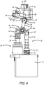
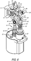
- FIGS. 1-7 show an electro-mechanical unlocking device 10 that can be used in an aircraft when a decompression event occurs.
- the electro-mechanical unlocking device 10 is often referred to herein as an unlocking device 10.
- the unlocking device 10 includes a locking or locked state ( FIG. 2 ), a holding state ( FIG. 3 ) and an unlocking or unlocked state ( FIG. 4 ).
- the unlocking device 10 also includes a locking sequence, which places the unlocking device 10 in the locking or locked state, a holding sequence that places the unlocking device 10 in the holding sequence and an unlocking sequence that places the unlocking device 10 in the unlocking or unlocked state.
- the unlocking device 10 generally includes a striker 12 that is movable between a first, locked or locking position and a second, unlocked or unlocking position, a sear 14 that is movable between a first position and a second position, an arming solenoid 16 that includes an energized state and a non-energized state, an arming assembly 18 that includes an arming armature 20 and an arming link 22, a crank 24 that is movable between a first position and a second position, a holding solenoid 26 that includes an energized state and a non-energized state, a holding armature 28 that is movable from a first position to a second position, and an unlock spring 30.
- all of these components are held or positioned within a frame 32 that provides a base for the necessary pivot points of some of the components and allowing the components to move between the first and second positions.
- the striker 12 is biased to the first position.
- a spring 34 can be used to bias the striker 12, as shown in FIG. 6 .
- the striker 12 is configured to maintain a latch bolt 100 in a normal position when the striker is in the first or locked position.
- FIG. 7 shows the striker 12 in both the first position (solid lines) and second position (dashed lines). It will be appreciated that the latch bolt 100 shown in FIG. 7 is only exemplary. In use in an aircraft, the unlocking device 10 is used to release something when a decompression event occurs.
- latch bolt or "decompression panel” is used herein generically to be any panel, latch bolt, wall, door, separating member or component thereof that separates two volumes (see first and second volumes 102 and 104 in FIG. 7 ) and moves or opens so that it no longer separates the two volumes when a decompression event occurs.
- the sear 14 is biased to the second position.
- the sear 14 blocks the striker or maintains the striker 12 in the first position, as shown in FIGS. 2 and 3 .
- the arming armature 20 is movable between a first position and a second position and is biased to the second position.
- a spring 35 can be used to bias the arming armature 20.
- the arming link 22 is movable between a first position and a second position.
- the crank 24 is biased to the second position, as shown in FIG. 4 .
- unlock spring 30 biases the crank 24 to the second position.
- Unlock spring 30 is installed on and is co-axial with connecting rod or holding armature 28.
- the unlock spring 30 is preloaded to about 19 LBF when in the armed condition, and about 6 LBF in the unarmed condition, with a total travel of about .100".
- these numbers are only exemplary and not limiting.
- the unlock spring extends between a flange 41 on the holding armature 28 and a portion of the frame 32. The compression and loading of the spring is preferably controlled by washers and shims (see components 39 in FIG. 3 ).
- the crank 24 is pivotable between the first position and the second position.
- the crank 24 includes a first arm 36, a second arm 38 and a third arm 40 that meet at a pivot portion 42 that is pivotably connected to the frame.
- the distal end of the first arm 36 contacts the sear 14, the second arm 38 is pivotably connected to the arming link 22, and the third arm 40 is pivotably connected to the holding armature 28.
- the unlocking device includes a locking sequence, a holding sequence and an unlocking sequence.
- the locking sequence will now be described.
- FIG. 4 shows the unlocking device in the unlocked position
- FIG. 2 shows the device in the locking position.
- the arming solenoid 16 switches to the energized state.
- the arming solenoid 16 is switched to the energized state
- the arming armature 20, arming link 22 move together from the second position to the first position.
- the arming assembly 18 moves the crank 24 from the second position to the first position.
- the crank 24 compresses the unlock spring 30, which moves the holding armature 28 from the second position to the first position.
- the holding solenoid 26 switches to the energized state and maintains the holding armature 28 in the first position.
- the crank 24 moves the sear 14 from the second position to the first position, and the sear blocks the striker 12 from moving from the first position to the second position.
- the unlocking device 10 is now locked.
- pivoting of the crank 24 from the second position to the first position compresses the unlock spring 30 and moves the holding armature 28 linearly from the second position to the first position.
- the sear 14 is pivotable between the first position and the second position.
- the distal end of the first arm 36 of the crank 24 includes a curved surface 46 that is associated or in contact with a crank interaction surface 48 on the sear 14.
- the crank interaction surface 48 which is preferably an inclined surface
- the curved surface 46 is a portion of a crank wheel 50 that is rotatably disposed on and a part of the first arm 36.
- the crank wheel 50 includes a cres outer sleeve, pressed over an aluminum spacer with a needle bearing at its center. This allows the crank 24 to rotate from the first position to the second position under heavy load against the sear with minimal friction to achieve the exemplary 3 ms reaction requirement.
- the crank wheel 50 In the first position, the crank wheel 50 (curved surface 46 or distal end of the first arm 36) contact a holding surface 52 of the sear to maintain the sear 14 in place. An angle is formed between the holding surface 52 and the crank interaction surface 48.
- the sear 14 includes a striker interaction portion 54 and the striker includes a curved surface 56 that is associated with the striker interaction portion 54.
- the striker interaction portion 54 (and, specifically, the lock surface 62 thereof) interacts with, is in contact with or blocks from movement the curved surface 56 on the striker 12.
- the curved surface is part of a striker wheel 58 that may roll or slides on an unlock surface 60 when the sear 14 is in the second position.
- the holding sequence position or state is shown in FIG. 3 .
- the arming solenoid 16 switches to the de-energized state.
- the arming armature 20 moves from the first position to the second position, thereby opening a gap 44 within the arming link 22 (as shown in FIG. 3 ) and between the arming armature and the arming link.
- the unlocking device 10 is now holding. This is the position the device will normally be in during operation of the aircraft.
- spring 35 moves the arming armature 20 to the second position when the arming solenoid 16 de-energizes, thus opening the gap 44. In this position, the sear 14 is in the first position and blocks movement of the striker 12 so the door cannot be opened.
- the unlocking sequence position or state is shown in FIG. 4 .
- the holding solenoid 26 switches to the de-energized state.
- the holding armature 28 moves from the first position to the second position and opens a gap 64.
- the unlock spring 30 moves the crank 24 from the first position to the second position.
- the sear 14 moves from the first position to the second position, thus unblocking the striker 12 and allowing the striker to move as a result of a decompression event or a person opening the door. It will be appreciated that the in moving the striker from the first to the second position to allow the door open, the force of spring 34 is overcome.
- pivotal movement of the crank 24 from the first position to the second position moves the arming link 22 linearly from the first position to the second position.
- the crank wheel 50 moves or rolls off of the holding surface 52.
- the sear 14 is biased to the second position (e.g., see spring 66 in FIG. 5 )
- the sear 14 pivots to the second position.
- the striker 12 is unblocked so it can move between first and second positions. In a decompression event the pressure pushes the latch bolt past the striker to open the door or other decompression panel.
- pivot points include pivot pins or pivot members 68 and the components that are biased may include a spring on or associated with the pivot pin or a pivot member.
Landscapes
- Physics & Mathematics (AREA)
- Electromagnetism (AREA)
- Engineering & Computer Science (AREA)
- Power Engineering (AREA)
- Lock And Its Accessories (AREA)
Applications Claiming Priority (1)
| Application Number | Priority Date | Filing Date | Title |
|---|---|---|---|
| US17/322,070 US11719020B2 (en) | 2021-05-17 | 2021-05-17 | Fast acting electro-mechanical unlocking device |
Publications (2)
| Publication Number | Publication Date |
|---|---|
| EP4092231A1 true EP4092231A1 (fr) | 2022-11-23 |
| EP4092231B1 EP4092231B1 (fr) | 2023-12-20 |
Family
ID=81654712
Family Applications (1)
| Application Number | Title | Priority Date | Filing Date |
|---|---|---|---|
| EP22173441.1A Active EP4092231B1 (fr) | 2021-05-17 | 2022-05-16 | Dispositif de déverrouillage électromécanique à action rapide et procédé pour l'actionnement d'un dispositif de déverrouillage électromécanique |
Country Status (3)
| Country | Link |
|---|---|
| US (2) | US11719020B2 (fr) |
| EP (1) | EP4092231B1 (fr) |
| HU (1) | HUE065012T2 (fr) |
Families Citing this family (2)
| Publication number | Priority date | Publication date | Assignee | Title |
|---|---|---|---|---|
| US11719020B2 (en) | 2021-05-17 | 2023-08-08 | Safran Cabin Inc. | Fast acting electro-mechanical unlocking device |
| US11965358B2 (en) * | 2022-01-03 | 2024-04-23 | Ankerslot Group B.V. | Strike linkage and in-wall receiver |
Citations (2)
| Publication number | Priority date | Publication date | Assignee | Title |
|---|---|---|---|---|
| EP0121517B1 (fr) * | 1982-09-30 | 1988-03-30 | The Boeing Company | Mecanisme de verrouillage de porte anti-detournement avec commande de derogation de decompression pneumatique |
| US20060102788A1 (en) * | 2004-10-15 | 2006-05-18 | Piorkowski Mitchell J | Increased security flight deck door strike apparatus and method |
Family Cites Families (22)
| Publication number | Priority date | Publication date | Assignee | Title |
|---|---|---|---|---|
| US4986584A (en) * | 1988-12-22 | 1991-01-22 | Adams Rite Manufacturing Company | Electrical strike release |
| US5636814A (en) * | 1990-04-05 | 1997-06-10 | The Boeing Company | Automatic clutch for a door latch handle |
| US6139073A (en) * | 1998-08-31 | 2000-10-31 | Westinghouse Air Brake Company | Lock assembly |
| US6866226B2 (en) | 2001-10-04 | 2005-03-15 | Hartwell Corporation | Pressure responsive blowout latch |
| US6866227B2 (en) | 2001-10-04 | 2005-03-15 | Hartwell Corporation | Pressure responsive blowout latch with reservoir |
| US6745982B2 (en) | 2002-01-16 | 2004-06-08 | Northwest Aerospace Technologies, Inc. | Pressure rate of change sensitive latching method and apparatus |
| US7055871B2 (en) * | 2003-07-18 | 2006-06-06 | Jackson Corp. | Electronic door lock dogging mechanism |
| FR2889228B1 (fr) * | 2005-07-27 | 2008-11-21 | Airbus France Sas | Dispositif de commande du verrouillage et deverrouillage d'une porte d'aeronef et porte d'aeronef integrant un tel dispositif |
| US8371626B2 (en) * | 2009-11-12 | 2013-02-12 | Textron Innovations Inc. | Fuselage door self-locking pin latch |
| WO2011069108A1 (fr) * | 2009-12-04 | 2011-06-09 | Hartwell Corporation | Verrou de sûreté haute répétabilité |
| EP2644495B1 (fr) * | 2012-03-27 | 2015-06-17 | AIRBUS HELICOPTERS DEUTSCHLAND GmbH | System d'ouverture d'urgence pour une porte de cabin d'avion |
| US8746024B2 (en) * | 2012-06-14 | 2014-06-10 | Aaron M. Baker | Rebound locking mechanism |
| EP3000720B1 (fr) * | 2014-09-23 | 2019-06-19 | AIRBUS HELICOPTERS DEUTSCHLAND GmbH | Système d'actionneur de porte d'aéronef |
| DE102015209249B4 (de) * | 2015-05-20 | 2021-05-06 | Kendrion Kuhnke Automation Gmbh | Verriegelung von Klappen |
| US10301846B2 (en) * | 2015-08-10 | 2019-05-28 | The Boeing Company | Release systems, methods, and apparatuses |
| US10024453B2 (en) * | 2016-07-15 | 2018-07-17 | Glen A. Robertson | Dual acting solenoid valve using bi-stable permanent magnet activation for energy efficiency and power versatility |
| WO2019195058A1 (fr) * | 2018-04-05 | 2019-10-10 | Harper Engineering Company | Appareil de verrouillage d'aéronef et ses procédés d'utilisation |
| EP3663190A1 (fr) * | 2018-12-07 | 2020-06-10 | Bombardier Inc. | Système de verrouillage et de blocage d'une porte d'aéronef |
| EP3871971B1 (fr) * | 2020-02-25 | 2022-02-16 | AIRBUS HELICOPTERS DEUTSCHLAND GmbH | Système d'actionnement d'une porte actionnable |
| US11719020B2 (en) | 2021-05-17 | 2023-08-08 | Safran Cabin Inc. | Fast acting electro-mechanical unlocking device |
| EP4098555B1 (fr) * | 2021-06-01 | 2023-08-02 | Airbus Operations GmbH | Unité de porte pour un véhicule |
| US11566459B1 (en) * | 2021-07-16 | 2023-01-31 | B/E Aerospace, Inc. | Concealed door hinge with shifting pivot point |
-
2021
- 2021-05-17 US US17/322,070 patent/US11719020B2/en active Active
-
2022
- 2022-05-16 EP EP22173441.1A patent/EP4092231B1/fr active Active
- 2022-05-16 HU HUE22173441A patent/HUE065012T2/hu unknown
-
2023
- 2023-07-07 US US18/219,237 patent/US12024925B2/en active Active
Patent Citations (2)
| Publication number | Priority date | Publication date | Assignee | Title |
|---|---|---|---|---|
| EP0121517B1 (fr) * | 1982-09-30 | 1988-03-30 | The Boeing Company | Mecanisme de verrouillage de porte anti-detournement avec commande de derogation de decompression pneumatique |
| US20060102788A1 (en) * | 2004-10-15 | 2006-05-18 | Piorkowski Mitchell J | Increased security flight deck door strike apparatus and method |
Also Published As
| Publication number | Publication date |
|---|---|
| US20230349194A1 (en) | 2023-11-02 |
| EP4092231B1 (fr) | 2023-12-20 |
| US20220364388A1 (en) | 2022-11-17 |
| HUE065012T2 (hu) | 2024-04-28 |
| US12024925B2 (en) | 2024-07-02 |
| US11719020B2 (en) | 2023-08-08 |
Similar Documents
| Publication | Publication Date | Title |
|---|---|---|
| US12024925B2 (en) | Fast acting electro-mechanical unlocking device | |
| EP3683138B1 (fr) | Système de verrouillage de porte doté d'un mécanisme de libération rapide | |
| EP1398437B1 (fr) | Mécanisme de verrouillage | |
| US5570915A (en) | Flush-mounted door latch | |
| CN103124824B (zh) | 机动车门锁 | |
| CA3002386C (fr) | Gache de porte electrique ayant une plateforme de liberation de pene demi-tour a cran d'arret actionnee par un element de retenue a ressort et un element de soulevement de pene a ressort | |
| WO2002055382A2 (fr) | Systeme de verrouillage pour porte de cockpit d'avion | |
| CN102187041A (zh) | 闩锁释放系统 | |
| US5953904A (en) | Lock for engine thrust reverser | |
| US11674334B2 (en) | Magnetically-triggered lock mechanism | |
| US5709421A (en) | Electromagnetic locking devices | |
| WO1984001404A1 (fr) | Mecanisme de verrouillage de porte anti-detournement avec commande de derogation de decompression pneumatique | |
| US3970339A (en) | Double swinging latchbolt | |
| US11572194B2 (en) | Aircraft door latch assembly | |
| JP2005263008A (ja) | コックピットドアのキャッチ装置 | |
| US20240018802A1 (en) | Handle Assembly for Escape Hatch | |
| US11318892B2 (en) | Vehicle interior component | |
| GB2290107A (en) | Door securing device | |
| US20080223092A1 (en) | Electromagnetic Lock Provided with a Sliding Bolt for a Swinging-Type Door | |
| NZ205412A (en) | Multiple bolt lock and electrically-energisable striker with multiple apertured alignable keeper | |
| EP3702557A1 (fr) | Contre-serrure pour battant inactif d'une double porte | |
| CN218751359U (zh) | 飞机舱门组件和包括该飞机舱门组件的飞机 | |
| JPH0316369Y2 (fr) | ||
| CN117355656B (zh) | 推拉门系统 | |
| TWM678725U (zh) | 泛用型具預壓釋放功能的陰極鎖 |
Legal Events
| Date | Code | Title | Description |
|---|---|---|---|
| PUAI | Public reference made under article 153(3) epc to a published international application that has entered the european phase |
Free format text: ORIGINAL CODE: 0009012 |
|
| STAA | Information on the status of an ep patent application or granted ep patent |
Free format text: STATUS: THE APPLICATION HAS BEEN PUBLISHED |
|
| AK | Designated contracting states |
Kind code of ref document: A1 Designated state(s): AL AT BE BG CH CY CZ DE DK EE ES FI FR GB GR HR HU IE IS IT LI LT LU LV MC MK MT NL NO PL PT RO RS SE SI SK SM TR |
|
| STAA | Information on the status of an ep patent application or granted ep patent |
Free format text: STATUS: REQUEST FOR EXAMINATION WAS MADE |
|
| 17P | Request for examination filed |
Effective date: 20230224 |
|
| RBV | Designated contracting states (corrected) |
Designated state(s): AL AT BE BG CH CY CZ DE DK EE ES FI FR GB GR HR HU IE IS IT LI LT LU LV MC MK MT NL NO PL PT RO RS SE SI SK SM TR |
|
| RIC1 | Information provided on ipc code assigned before grant |
Ipc: B64C 1/14 20060101ALI20230720BHEP Ipc: E05B 15/02 20060101ALI20230720BHEP Ipc: E05B 47/00 20060101AFI20230720BHEP |
|
| GRAP | Despatch of communication of intention to grant a patent |
Free format text: ORIGINAL CODE: EPIDOSNIGR1 |
|
| STAA | Information on the status of an ep patent application or granted ep patent |
Free format text: STATUS: GRANT OF PATENT IS INTENDED |
|
| INTG | Intention to grant announced |
Effective date: 20230828 |
|
| GRAS | Grant fee paid |
Free format text: ORIGINAL CODE: EPIDOSNIGR3 |
|
| GRAA | (expected) grant |
Free format text: ORIGINAL CODE: 0009210 |
|
| STAA | Information on the status of an ep patent application or granted ep patent |
Free format text: STATUS: THE PATENT HAS BEEN GRANTED |
|
| AK | Designated contracting states |
Kind code of ref document: B1 Designated state(s): AL AT BE BG CH CY CZ DE DK EE ES FI FR GB GR HR HU IE IS IT LI LT LU LV MC MK MT NL NO PL PT RO RS SE SI SK SM TR |
|
| REG | Reference to a national code |
Ref country code: GB Ref legal event code: FG4D |
|
| REG | Reference to a national code |
Ref country code: DE Ref legal event code: R096 Ref document number: 602022001366 Country of ref document: DE |
|
| REG | Reference to a national code |
Ref country code: CH Ref legal event code: EP |
|
| REG | Reference to a national code |
Ref country code: IE Ref legal event code: FG4D |
|
| PG25 | Lapsed in a contracting state [announced via postgrant information from national office to epo] |
Ref country code: GR Free format text: LAPSE BECAUSE OF FAILURE TO SUBMIT A TRANSLATION OF THE DESCRIPTION OR TO PAY THE FEE WITHIN THE PRESCRIBED TIME-LIMIT Effective date: 20240321 |
|
| REG | Reference to a national code |
Ref country code: LT Ref legal event code: MG9D |
|
| PG25 | Lapsed in a contracting state [announced via postgrant information from national office to epo] |
Ref country code: LT Free format text: LAPSE BECAUSE OF FAILURE TO SUBMIT A TRANSLATION OF THE DESCRIPTION OR TO PAY THE FEE WITHIN THE PRESCRIBED TIME-LIMIT Effective date: 20231220 |
|
| REG | Reference to a national code |
Ref country code: NL Ref legal event code: MP Effective date: 20231220 |
|
| PG25 | Lapsed in a contracting state [announced via postgrant information from national office to epo] |
Ref country code: ES Free format text: LAPSE BECAUSE OF FAILURE TO SUBMIT A TRANSLATION OF THE DESCRIPTION OR TO PAY THE FEE WITHIN THE PRESCRIBED TIME-LIMIT Effective date: 20231220 |
|
| REG | Reference to a national code |
Ref country code: HU Ref legal event code: AG4A Ref document number: E065012 Country of ref document: HU |
|
| PG25 | Lapsed in a contracting state [announced via postgrant information from national office to epo] |
Ref country code: LT Free format text: LAPSE BECAUSE OF FAILURE TO SUBMIT A TRANSLATION OF THE DESCRIPTION OR TO PAY THE FEE WITHIN THE PRESCRIBED TIME-LIMIT Effective date: 20231220 Ref country code: GR Free format text: LAPSE BECAUSE OF FAILURE TO SUBMIT A TRANSLATION OF THE DESCRIPTION OR TO PAY THE FEE WITHIN THE PRESCRIBED TIME-LIMIT Effective date: 20240321 Ref country code: FI Free format text: LAPSE BECAUSE OF FAILURE TO SUBMIT A TRANSLATION OF THE DESCRIPTION OR TO PAY THE FEE WITHIN THE PRESCRIBED TIME-LIMIT Effective date: 20231220 Ref country code: ES Free format text: LAPSE BECAUSE OF FAILURE TO SUBMIT A TRANSLATION OF THE DESCRIPTION OR TO PAY THE FEE WITHIN THE PRESCRIBED TIME-LIMIT Effective date: 20231220 Ref country code: BG Free format text: LAPSE BECAUSE OF FAILURE TO SUBMIT A TRANSLATION OF THE DESCRIPTION OR TO PAY THE FEE WITHIN THE PRESCRIBED TIME-LIMIT Effective date: 20240320 |
|
| PG25 | Lapsed in a contracting state [announced via postgrant information from national office to epo] |
Ref country code: NL Free format text: LAPSE BECAUSE OF FAILURE TO SUBMIT A TRANSLATION OF THE DESCRIPTION OR TO PAY THE FEE WITHIN THE PRESCRIBED TIME-LIMIT Effective date: 20231220 |
|
| PG25 | Lapsed in a contracting state [announced via postgrant information from national office to epo] |
Ref country code: SE Free format text: LAPSE BECAUSE OF FAILURE TO SUBMIT A TRANSLATION OF THE DESCRIPTION OR TO PAY THE FEE WITHIN THE PRESCRIBED TIME-LIMIT Effective date: 20231220 Ref country code: RS Free format text: LAPSE BECAUSE OF FAILURE TO SUBMIT A TRANSLATION OF THE DESCRIPTION OR TO PAY THE FEE WITHIN THE PRESCRIBED TIME-LIMIT Effective date: 20231220 Ref country code: NO Free format text: LAPSE BECAUSE OF FAILURE TO SUBMIT A TRANSLATION OF THE DESCRIPTION OR TO PAY THE FEE WITHIN THE PRESCRIBED TIME-LIMIT Effective date: 20240320 Ref country code: NL Free format text: LAPSE BECAUSE OF FAILURE TO SUBMIT A TRANSLATION OF THE DESCRIPTION OR TO PAY THE FEE WITHIN THE PRESCRIBED TIME-LIMIT Effective date: 20231220 Ref country code: LV Free format text: LAPSE BECAUSE OF FAILURE TO SUBMIT A TRANSLATION OF THE DESCRIPTION OR TO PAY THE FEE WITHIN THE PRESCRIBED TIME-LIMIT Effective date: 20231220 Ref country code: HR Free format text: LAPSE BECAUSE OF FAILURE TO SUBMIT A TRANSLATION OF THE DESCRIPTION OR TO PAY THE FEE WITHIN THE PRESCRIBED TIME-LIMIT Effective date: 20231220 |
|
| PG25 | Lapsed in a contracting state [announced via postgrant information from national office to epo] |
Ref country code: IS Free format text: LAPSE BECAUSE OF FAILURE TO SUBMIT A TRANSLATION OF THE DESCRIPTION OR TO PAY THE FEE WITHIN THE PRESCRIBED TIME-LIMIT Effective date: 20240420 |
|
| PG25 | Lapsed in a contracting state [announced via postgrant information from national office to epo] |
Ref country code: CZ Free format text: LAPSE BECAUSE OF FAILURE TO SUBMIT A TRANSLATION OF THE DESCRIPTION OR TO PAY THE FEE WITHIN THE PRESCRIBED TIME-LIMIT Effective date: 20231220 |
|
| PG25 | Lapsed in a contracting state [announced via postgrant information from national office to epo] |
Ref country code: SK Free format text: LAPSE BECAUSE OF FAILURE TO SUBMIT A TRANSLATION OF THE DESCRIPTION OR TO PAY THE FEE WITHIN THE PRESCRIBED TIME-LIMIT Effective date: 20231220 |
|
| PG25 | Lapsed in a contracting state [announced via postgrant information from national office to epo] |
Ref country code: SM Free format text: LAPSE BECAUSE OF FAILURE TO SUBMIT A TRANSLATION OF THE DESCRIPTION OR TO PAY THE FEE WITHIN THE PRESCRIBED TIME-LIMIT Effective date: 20231220 Ref country code: SK Free format text: LAPSE BECAUSE OF FAILURE TO SUBMIT A TRANSLATION OF THE DESCRIPTION OR TO PAY THE FEE WITHIN THE PRESCRIBED TIME-LIMIT Effective date: 20231220 Ref country code: RO Free format text: LAPSE BECAUSE OF FAILURE TO SUBMIT A TRANSLATION OF THE DESCRIPTION OR TO PAY THE FEE WITHIN THE PRESCRIBED TIME-LIMIT Effective date: 20231220 Ref country code: IT Free format text: LAPSE BECAUSE OF FAILURE TO SUBMIT A TRANSLATION OF THE DESCRIPTION OR TO PAY THE FEE WITHIN THE PRESCRIBED TIME-LIMIT Effective date: 20231220 Ref country code: IS Free format text: LAPSE BECAUSE OF FAILURE TO SUBMIT A TRANSLATION OF THE DESCRIPTION OR TO PAY THE FEE WITHIN THE PRESCRIBED TIME-LIMIT Effective date: 20240420 Ref country code: EE Free format text: LAPSE BECAUSE OF FAILURE TO SUBMIT A TRANSLATION OF THE DESCRIPTION OR TO PAY THE FEE WITHIN THE PRESCRIBED TIME-LIMIT Effective date: 20231220 Ref country code: CZ Free format text: LAPSE BECAUSE OF FAILURE TO SUBMIT A TRANSLATION OF THE DESCRIPTION OR TO PAY THE FEE WITHIN THE PRESCRIBED TIME-LIMIT Effective date: 20231220 |
|
| PG25 | Lapsed in a contracting state [announced via postgrant information from national office to epo] |
Ref country code: PL Free format text: LAPSE BECAUSE OF FAILURE TO SUBMIT A TRANSLATION OF THE DESCRIPTION OR TO PAY THE FEE WITHIN THE PRESCRIBED TIME-LIMIT Effective date: 20231220 Ref country code: PT Free format text: LAPSE BECAUSE OF FAILURE TO SUBMIT A TRANSLATION OF THE DESCRIPTION OR TO PAY THE FEE WITHIN THE PRESCRIBED TIME-LIMIT Effective date: 20240422 |
|
| PG25 | Lapsed in a contracting state [announced via postgrant information from national office to epo] |
Ref country code: PT Free format text: LAPSE BECAUSE OF FAILURE TO SUBMIT A TRANSLATION OF THE DESCRIPTION OR TO PAY THE FEE WITHIN THE PRESCRIBED TIME-LIMIT Effective date: 20240422 Ref country code: PL Free format text: LAPSE BECAUSE OF FAILURE TO SUBMIT A TRANSLATION OF THE DESCRIPTION OR TO PAY THE FEE WITHIN THE PRESCRIBED TIME-LIMIT Effective date: 20231220 |
|
| REG | Reference to a national code |
Ref country code: DE Ref legal event code: R097 Ref document number: 602022001366 Country of ref document: DE |
|
| PG25 | Lapsed in a contracting state [announced via postgrant information from national office to epo] |
Ref country code: DK Free format text: LAPSE BECAUSE OF FAILURE TO SUBMIT A TRANSLATION OF THE DESCRIPTION OR TO PAY THE FEE WITHIN THE PRESCRIBED TIME-LIMIT Effective date: 20231220 |
|
| PLBE | No opposition filed within time limit |
Free format text: ORIGINAL CODE: 0009261 |
|
| STAA | Information on the status of an ep patent application or granted ep patent |
Free format text: STATUS: NO OPPOSITION FILED WITHIN TIME LIMIT |
|
| PG25 | Lapsed in a contracting state [announced via postgrant information from national office to epo] |
Ref country code: SI Free format text: LAPSE BECAUSE OF FAILURE TO SUBMIT A TRANSLATION OF THE DESCRIPTION OR TO PAY THE FEE WITHIN THE PRESCRIBED TIME-LIMIT Effective date: 20231220 |
|
| PG25 | Lapsed in a contracting state [announced via postgrant information from national office to epo] |
Ref country code: SI Free format text: LAPSE BECAUSE OF FAILURE TO SUBMIT A TRANSLATION OF THE DESCRIPTION OR TO PAY THE FEE WITHIN THE PRESCRIBED TIME-LIMIT Effective date: 20231220 Ref country code: DK Free format text: LAPSE BECAUSE OF FAILURE TO SUBMIT A TRANSLATION OF THE DESCRIPTION OR TO PAY THE FEE WITHIN THE PRESCRIBED TIME-LIMIT Effective date: 20231220 |
|
| 26N | No opposition filed |
Effective date: 20240923 |
|
| PG25 | Lapsed in a contracting state [announced via postgrant information from national office to epo] |
Ref country code: MC Free format text: LAPSE BECAUSE OF FAILURE TO SUBMIT A TRANSLATION OF THE DESCRIPTION OR TO PAY THE FEE WITHIN THE PRESCRIBED TIME-LIMIT Effective date: 20231220 |
|
| PG25 | Lapsed in a contracting state [announced via postgrant information from national office to epo] |
Ref country code: LU Free format text: LAPSE BECAUSE OF NON-PAYMENT OF DUE FEES Effective date: 20240516 |
|
| PG25 | Lapsed in a contracting state [announced via postgrant information from national office to epo] |
Ref country code: MC Free format text: LAPSE BECAUSE OF FAILURE TO SUBMIT A TRANSLATION OF THE DESCRIPTION OR TO PAY THE FEE WITHIN THE PRESCRIBED TIME-LIMIT Effective date: 20231220 Ref country code: LU Free format text: LAPSE BECAUSE OF NON-PAYMENT OF DUE FEES Effective date: 20240516 |
|
| REG | Reference to a national code |
Ref country code: BE Ref legal event code: MM Effective date: 20240531 |
|
| REG | Reference to a national code |
Ref country code: AT Ref legal event code: UEP Ref document number: 1642571 Country of ref document: AT Kind code of ref document: T Effective date: 20231220 |
|
| PG25 | Lapsed in a contracting state [announced via postgrant information from national office to epo] |
Ref country code: IE Free format text: LAPSE BECAUSE OF NON-PAYMENT OF DUE FEES Effective date: 20240516 |
|
| PG25 | Lapsed in a contracting state [announced via postgrant information from national office to epo] |
Ref country code: BE Free format text: LAPSE BECAUSE OF NON-PAYMENT OF DUE FEES Effective date: 20240531 |
|
| PGFP | Annual fee paid to national office [announced via postgrant information from national office to epo] |
Ref country code: DE Payment date: 20250519 Year of fee payment: 4 |
|
| PGFP | Annual fee paid to national office [announced via postgrant information from national office to epo] |
Ref country code: HU Payment date: 20250512 Year of fee payment: 4 |
|
| PGFP | Annual fee paid to national office [announced via postgrant information from national office to epo] |
Ref country code: FR Payment date: 20250526 Year of fee payment: 4 |
|
| PGFP | Annual fee paid to national office [announced via postgrant information from national office to epo] |
Ref country code: AT Payment date: 20250721 Year of fee payment: 4 |
|
| PG25 | Lapsed in a contracting state [announced via postgrant information from national office to epo] |
Ref country code: CY Free format text: LAPSE BECAUSE OF FAILURE TO SUBMIT A TRANSLATION OF THE DESCRIPTION OR TO PAY THE FEE WITHIN THE PRESCRIBED TIME-LIMIT; INVALID AB INITIO Effective date: 20220516 |
|
| REG | Reference to a national code |
Ref country code: CH Ref legal event code: H13 Free format text: ST27 STATUS EVENT CODE: U-0-0-H10-H13 (AS PROVIDED BY THE NATIONAL OFFICE) Effective date: 20251223 |
|
| PG25 | Lapsed in a contracting state [announced via postgrant information from national office to epo] |
Ref country code: CH Free format text: LAPSE BECAUSE OF NON-PAYMENT OF DUE FEES Effective date: 20250531 |