EP4092283A1 - Procédé d'enroulement de stator de palier magnétique radial, stator de palier magnétique radial et palier magnétique radial - Google Patents
Procédé d'enroulement de stator de palier magnétique radial, stator de palier magnétique radial et palier magnétique radial Download PDFInfo
- Publication number
- EP4092283A1 EP4092283A1 EP22174432.9A EP22174432A EP4092283A1 EP 4092283 A1 EP4092283 A1 EP 4092283A1 EP 22174432 A EP22174432 A EP 22174432A EP 4092283 A1 EP4092283 A1 EP 4092283A1
- Authority
- EP
- European Patent Office
- Prior art keywords
- stator
- winding
- magnetic bearing
- coil
- radial magnetic
- Prior art date
- Legal status (The legal status is an assumption and is not a legal conclusion. Google has not performed a legal analysis and makes no representation as to the accuracy of the status listed.)
- Granted
Links
Images
Classifications
-
- F—MECHANICAL ENGINEERING; LIGHTING; HEATING; WEAPONS; BLASTING
- F16—ENGINEERING ELEMENTS AND UNITS; GENERAL MEASURES FOR PRODUCING AND MAINTAINING EFFECTIVE FUNCTIONING OF MACHINES OR INSTALLATIONS; THERMAL INSULATION IN GENERAL
- F16C—SHAFTS; FLEXIBLE SHAFTS; ELEMENTS OR CRANKSHAFT MECHANISMS; ROTARY BODIES OTHER THAN GEARING ELEMENTS; BEARINGS
- F16C32/00—Bearings not otherwise provided for
- F16C32/04—Bearings not otherwise provided for using magnetic or electric supporting means
- F16C32/0406—Magnetic bearings
- F16C32/044—Active magnetic bearings
- F16C32/047—Details of housings; Mounting of active magnetic bearings
-
- F—MECHANICAL ENGINEERING; LIGHTING; HEATING; WEAPONS; BLASTING
- F16—ENGINEERING ELEMENTS AND UNITS; GENERAL MEASURES FOR PRODUCING AND MAINTAINING EFFECTIVE FUNCTIONING OF MACHINES OR INSTALLATIONS; THERMAL INSULATION IN GENERAL
- F16C—SHAFTS; FLEXIBLE SHAFTS; ELEMENTS OR CRANKSHAFT MECHANISMS; ROTARY BODIES OTHER THAN GEARING ELEMENTS; BEARINGS
- F16C32/00—Bearings not otherwise provided for
- F16C32/04—Bearings not otherwise provided for using magnetic or electric supporting means
- F16C32/0406—Magnetic bearings
- F16C32/044—Active magnetic bearings
- F16C32/0459—Details of the magnetic circuit
- F16C32/0461—Details of the magnetic circuit of stationary parts of the magnetic circuit
-
- F—MECHANICAL ENGINEERING; LIGHTING; HEATING; WEAPONS; BLASTING
- F16—ENGINEERING ELEMENTS AND UNITS; GENERAL MEASURES FOR PRODUCING AND MAINTAINING EFFECTIVE FUNCTIONING OF MACHINES OR INSTALLATIONS; THERMAL INSULATION IN GENERAL
- F16C—SHAFTS; FLEXIBLE SHAFTS; ELEMENTS OR CRANKSHAFT MECHANISMS; ROTARY BODIES OTHER THAN GEARING ELEMENTS; BEARINGS
- F16C32/00—Bearings not otherwise provided for
- F16C32/04—Bearings not otherwise provided for using magnetic or electric supporting means
- F16C32/0406—Magnetic bearings
- F16C32/044—Active magnetic bearings
- F16C32/0474—Active magnetic bearings for rotary movement
- F16C32/048—Active magnetic bearings for rotary movement with active support of two degrees of freedom, e.g. radial magnetic bearings
-
- F—MECHANICAL ENGINEERING; LIGHTING; HEATING; WEAPONS; BLASTING
- F16—ENGINEERING ELEMENTS AND UNITS; GENERAL MEASURES FOR PRODUCING AND MAINTAINING EFFECTIVE FUNCTIONING OF MACHINES OR INSTALLATIONS; THERMAL INSULATION IN GENERAL
- F16C—SHAFTS; FLEXIBLE SHAFTS; ELEMENTS OR CRANKSHAFT MECHANISMS; ROTARY BODIES OTHER THAN GEARING ELEMENTS; BEARINGS
- F16C32/00—Bearings not otherwise provided for
- F16C32/04—Bearings not otherwise provided for using magnetic or electric supporting means
- F16C32/0406—Magnetic bearings
- F16C32/044—Active magnetic bearings
-
- H—ELECTRICITY
- H01—ELECTRIC ELEMENTS
- H01F—MAGNETS; INDUCTANCES; TRANSFORMERS; SELECTION OF MATERIALS FOR THEIR MAGNETIC PROPERTIES
- H01F41/00—Apparatus or processes specially adapted for manufacturing or assembling magnets, inductances or transformers; Apparatus or processes specially adapted for manufacturing materials characterised by their magnetic properties
- H01F41/02—Apparatus or processes specially adapted for manufacturing or assembling magnets, inductances or transformers; Apparatus or processes specially adapted for manufacturing materials characterised by their magnetic properties for manufacturing cores, coils, or magnets
- H01F41/04—Apparatus or processes specially adapted for manufacturing or assembling magnets, inductances or transformers; Apparatus or processes specially adapted for manufacturing materials characterised by their magnetic properties for manufacturing cores, coils, or magnets for manufacturing coils
- H01F41/06—Coil winding
- H01F41/098—Mandrels; Formers
-
- H—ELECTRICITY
- H01—ELECTRIC ELEMENTS
- H01F—MAGNETS; INDUCTANCES; TRANSFORMERS; SELECTION OF MATERIALS FOR THEIR MAGNETIC PROPERTIES
- H01F5/00—Coils
- H01F5/02—Coils wound on non-magnetic supports, e.g. formers
-
- H—ELECTRICITY
- H02—GENERATION; CONVERSION OR DISTRIBUTION OF ELECTRIC POWER
- H02K—DYNAMO-ELECTRIC MACHINES
- H02K1/00—Details of the magnetic circuit
- H02K1/06—Details of the magnetic circuit characterised by the shape, form or construction
- H02K1/12—Stationary parts of the magnetic circuit
- H02K1/14—Stator cores with salient poles
- H02K1/146—Stator cores with salient poles consisting of a generally annular yoke with salient poles
-
- H—ELECTRICITY
- H02—GENERATION; CONVERSION OR DISTRIBUTION OF ELECTRIC POWER
- H02K—DYNAMO-ELECTRIC MACHINES
- H02K3/00—Details of windings
- H02K3/04—Windings characterised by the conductor shape, form or construction, e.g. with bar conductors
- H02K3/28—Layout of windings or of connections between windings
-
- H—ELECTRICITY
- H02—GENERATION; CONVERSION OR DISTRIBUTION OF ELECTRIC POWER
- H02K—DYNAMO-ELECTRIC MACHINES
- H02K3/00—Details of windings
- H02K3/46—Fastening of windings on the stator or rotor structure
- H02K3/48—Fastening of windings on the stator or rotor structure in slots
-
- H—ELECTRICITY
- H02—GENERATION; CONVERSION OR DISTRIBUTION OF ELECTRIC POWER
- H02K—DYNAMO-ELECTRIC MACHINES
- H02K3/00—Details of windings
- H02K3/46—Fastening of windings on the stator or rotor structure
- H02K3/52—Fastening salient pole windings or connections thereto
- H02K3/521—Fastening salient pole windings or connections thereto applicable to stators only
- H02K3/522—Fastening salient pole windings or connections thereto applicable to stators only for generally annular cores with salient poles
-
- H—ELECTRICITY
- H02—GENERATION; CONVERSION OR DISTRIBUTION OF ELECTRIC POWER
- H02K—DYNAMO-ELECTRIC MACHINES
- H02K7/00—Arrangements for handling mechanical energy structurally associated with dynamo-electric machines, e.g. structural association with mechanical driving motors or auxiliary dynamo-electric machines
- H02K7/08—Structural association with bearings
- H02K7/09—Structural association with bearings with magnetic bearings
-
- H—ELECTRICITY
- H02—GENERATION; CONVERSION OR DISTRIBUTION OF ELECTRIC POWER
- H02K—DYNAMO-ELECTRIC MACHINES
- H02K2203/00—Specific aspects not provided for in the other groups of this subclass relating to the windings
- H02K2203/12—Machines characterised by the bobbins for supporting the windings
Definitions
- the present invention relates to the field of manufacture of radial magnetic bearing parts, in particular to a winding method for radial magnetic bearing stator and a radial magnetic bearing stator and a radial magnetic bearing made using the same.
- stator slot space factor refers to the ratio of the space occupied by the coils of the stator winding in the stator slot after it is placed in the stator slot.
- a higher slot space factor means that a stator of the same size is equipped with a stator winding with more coils, so it can also generate a stronger magnetic field at the same current.
- the free winding process can be fully utilized to achieve a higher slot space factor, in practice, however, the requirements of the winding process is higher, and problems such as winding spread out or even fall off would readily occur.
- the windings the winding process of which is completed in advance on wound bobbins or the like, they will be restricted by the opening width of the stator slot and the assembly process.
- the thickness of the winding shall not exceed the opening width of the stator slot, and it should also be ensured that the stator windings on the adjacent teeth sharing the stator slot can be mounted smoothly. As a result, the winding thickness is restricted in many ways, and the slot space factor is restricted accordingly.
- the present application aims to provide a winding method for radial magnetic bearing stator, a radial magnetic bearing stator and a radial magnetic bearing, so as to at least partially solve or alleviate the problems existing in the prior art.
- a winding method for radial magnetic bearing stator comprises: S110, sleeving a first formed stator winding on a first stator tooth of a stator core along a radial outward direction; S120, sleeving a second formed stator winding on a second stator tooth of the stator core along a radial outward direction; S130, connecting a first coil of the first formed stator winding in series with a second coil of the second formed stator winding; wherein the first stator tooth is adjacent to the second stator tooth, and a stator slot is formed therebetween; and the coil number of the first formed stator winding is larger than that of the second formed stator winding.
- step S110 it further comprises: S100, winding the first coil on a first wound bobbin to form the first formed stator winding, and winding the second coil on a second wound bobbin to form the second formed stator winding; wherein the first wound bobbin and the second wound bobbin provide a radial limitation for the first coil and the second coil, respectively.
- the first coil is wound with respect to the first wound bobbin to have a first thickness, wherein the first thickness is approximately the width of the opening of the stator slot in the direction perpendicular to the slot wall of the stator slot.
- the first coil is wound with respect to the first wound bobbin to have a varying thickness; wherein the first coil with the varying thickness forms a tapered angle at the radial inner end of the first wound bobbin, and the maximum thickness of the coil of the second formed stator winding that can be sleeved on the second stator tooth is limited between the tapered angle and the second stator teeth.
- the tapered angle formed by the first coil is parallel to the included angle of the opening of the stator slot.
- one of the first formed stator windings is corresponding to one of the second formed stator windings, and one of the first stator teeth is corresponding to one of the second stator teeth adjacent to one side of the first stator tooth; or, when the radial magnetic bearing stator is a twelve-pole stator, one of the first formed stator windings is corresponding to two of the second formed stator windings, and one of the first stator teeth is corresponding to two of the second stator teeth adjacent to both sides of the first stator tooth.
- a radial magnetic bearing stator which comprises: a stator core having a stator yoke and adjacent first and second stator teeth disposed along the stator yoke, with a stator slot formed therebetween; a first formed stator winding sleeved on the first stator tooth of the stator core along a radial outward direction; and a second formed stator winding sleeved on the second stator tooth of the stator core along a radial outward direction; wherein a first coil of the first formed stator winding is connected in series with a second coil of the second formed stator winding; and the coil number of the first formed stator winding is larger than that of the second formed stator winding.
- the first formed stator winding comprises: a first wound bobbin having a first main body and first end stop walls disposed at both ends of the first main body; the first coil is wound on the first wound bobbin, and is limited by the first end stop walls in the radial direction; and/or the second formed stator winding comprises: a second wound bobbin having a second main body and second end stop walls disposed at both ends of the second main body; the second coil is wound on the second wound bobbin, and is limited by the second end stop walls in the radial direction.
- the maximum thickness of the first coil wound on the first wound bobbin is approximately the width of the opening of the stator slot in the direction perpendicular to the slot wall of the stator slot.
- the first coil wound on the first wound bobbin forms a tapered angle at the inner radial end of the first wound bobbin, and the maximum thickness of the coil of the second formed stator winding that can be sleeved on the second stator tooth is limited between the tapered angle and the second stator tooth.
- the tapered angle formed by the first coil is parallel to the included angle of the opening of the stator slot.
- one of the first formed stator windings corresponds to one of the second formed stator windings, and one of the first stator teeth corresponds to one of the second stator teeth adjacent to one side of the first stator tooth; or, when the radial magnetic bearing stator is a twelve-pole stator, one of the first formed stator windings corresponds to two of the second formed stator windings, and one of the first stator teeth corresponds to two of the second stator teeth adjacent to both sides of the first stator tooth.
- a radial magnetic bearing which comprises the aforementioned radial magnetic bearing stator.
- stator winding method for radial magnetic bearing stator and the radial magnetic bearing stator and the radial magnetic bearing made using the same of the present application different formed stator windings the coil winding of which has been completed are successively sleeved on different stator teeth of the stator core, the first formed stator winding mounted in advance has more coils than the second formed stator winding, and the coils of the two are connected in series.
- stator windings for any set of stator windings that generate a magnetic field, they have the same total coil number, and can achieve a higher slot space factor, which improves the work efficiency of the radial magnetic bearing without increasing the stator size and maintaining the low cost as well.
- the axial direction, the radial direction and the circumferential direction are introduced herein as the reference coordinate system.
- the way of describing directions is used to express the structural characteristics of the respective components and the relative positional relationships therebetween, but not to restrict their absolute positional relationships.
- the axial direction means that a number of stator sheets of the radial magnetic bearing stator are stacked in the lamination direction of the stator core, the radial direction refers to the extension direction of the stator core radius, and the circumferential direction refers to the peripheral direction of the stator core.
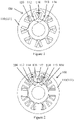
- FIGS. 1 and 2 a plurality of the radial magnetic bearing stator are illustrated.
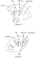
- FIGS. 3 and 4 illustrate the mounting process of the formed stator windings.
- Most of the arrangements of the radial magnetic bearing stators in these embodiments are similar. The difference mainly lies in the way the coil is connected between the windings when having different number of poles.
- the common characteristics of these embodiments of the winding method for radial magnetic bearing stator will be introduced first as follows, and then the unique characteristics thereof will be described with reference to different drawings.
- a radial magnetic bearing stator 100 shown in the figure comprises a stator core 110 formed by stacking a number of stator sheets.
- the stator core 110 has a stator yoke 111 and adjacent first stator teeth 112 and second stator teeth 113 disposed along the stator yoke 111, wherein a stator slot 114 is formed between the first stator teeth 112 and the second stator teeth 113.
- the winding method for radial magnetic bearing stator in this embodiment comprises at least two steps: firstly, S110 (as shown in FIG. 3 ) is performed, i.e., a first formed stator winding 120 with more coils is sleeved on the first stator tooth 112 of the stator core 110 along a radial outward direction. S120 is then performed (as shown in FIG.
- a second formed stator winding 130 with less coils to be connected in series with the first formed stator winding 120 is sleeved on the second stator tooth 113 of the stator core 110 along a radial outward direction.
- S130 is performed such that the first coil 121 of the first formed stator winding 120 is connected in series with the second coil 131 of the second formed stator winding 130.
- the number of coils that can be arranged in the stator slot can be increased as much as possible, thereby improving the slot space factor.
- the first formed stator winding 120 and the second formed stator winding 130 as a set with coils thereof connected in series, it can be ensured that for any set of stator windings that generate a magnetic field, they still have the same total coil numbers, so the magnetic field generated will not be offset due to the inconsistent coils of each winding.
- the work efficiency of the radial magnetic bearing is improved without increasing the stator size and maintaining the low cost as well.
- the method may further comprise step S100: winding the first coil 121 on a first wound bobbin 122 to form the first formed stator winding 120, and winding the second coil 131 on a second wound bobbin 132 to form the second formed stator winding 130.
- the first formed stator winding 120 thus formed comprises the first wound bobbin 122 and the first coil 121, and the first wound bobbin 122 has a first main body 1221 configured as a sleeve structure with a through hole.
- the through hole matches with the outer contour of the first stator tooth 112, such that the first main body 1221 is mounted on the first stator tooth 112 through the through hole.
- the first wound bobbin 122 also has first end stop walls 1222 disposed at both ends of the first main body 1221 to form a disc-shaped structure, and the middle portion thereof is kept open to avoid blocking of the through hole of the first main body 1221. With the help of the first end stop walls 1222, when the first coil 121 is wound on the first main body 1221 until it abuts against the first end stop walls 1222 on both sides, it will be limited by the first end stop walls 1222 along the radial direction.
- the second wound bobbin 132 has a second main body 1321 also configured as a sleeve structure with a through hole.
- the through hole matches with the outer contour of the second stator teeth 113, such that the second main body 1321 is mounted on the second stator teeth 113 through the through hole.
- the second wound bobbin 132 also has second end stop walls 1322 disposed at both ends of the second main body 1321 to form a disc-shaped structure, and the middle portion thereof is kept open to avoid blocking of the through hole of the second main body 1321.
- the first coil 121 can also be wound with respect to the first wound bobbin 122 to have a first thickness T, and the first thickness T may be approximately the width W in the opening direction of the stator slot 114 in the direction perpendicular to the slot wall of the stator slot 114.
- this step realizes that the first formed stator winding 120 mounted on the radial magnetic bearing stator has almost the largest possible coil number.
- the first coil 121 can also be wound with respect to the first wound bobbin 122 to have a varying thickness; wherein the first coil 121 with the varying thickness forms a tapered angle a at the radial inner end of the first wound bobbin 122, and the maximum thickness of the coil of the second formed stator winding 130 that can be sleeved on the second stator teeth 113 is limited between the tapered angle a thus formed and the second stator teeth 113.
- the number of coils of the second formed stator winding 130 that can possibly be mounted is also taken into consideration.
- the number of coils of the second formed stator winding 130 is adjusted by adjusting the contour enclosed by the first coil 121 wound with respect to the first wound bobbin 122 on the first formed stator winding 120, so that the second formed stator winding 130 can also have a relatively lager coil number, and the sum of the coil number of the two winding can be increased finally
- the winding method can be adjusted so that the tapered angle a formed by the first coil 121 is parallel to the side wall of the second stator tooth 113, that is, the angle a is substantially parallel and equal to the included angle of the opening of the stator slot (that is, the auxiliary dotted line of the tapered angle a shown in FIG. 3 is parallel to the left side wall of the second stator tooth 113; in other words, the tapered angle a shown in FIG. 3 is substantially the same as the included angle b of the left side wall of the second stator tooth 113 with respect to the first wound bobbin 122).
- the coil number of the second formed stator winding 130 can be further increased.
- stator 100 when the aforementioned winding method is applied to the eight-pole radial magnetic bearing stator 100, it is arranged such that a first formed stator winding 120 corresponds to a second formed stator winding 130, and the two are made to become a set of windings connected in series with each other. And at this time, two stator teeth are provided for mounting these windings, i.e., a first stator tooth 112 and a corresponding second stator teeth 113 adjacent to one side of the first stator tooth 112.
- FIG. 2 when the aforementioned winding method is applied to the twelve-pole radial magnetic bearing stator 100, it is arranged such that a first formed stator winding 120 corresponds to two second formed stator windings 130, and the three are made to become a set of windings connected in series with each other. And at this time, three stator teeth are provided for mounting these windings, i.e., a first stator tooth 112 and two corresponding second stator teeth 113 adjacent to both sides of the first stator tooth 112.
- a radial magnetic bearing according to the present application is further provided herein.
- the radial magnetic bearing comprises a radial magnetic bearing stator according to any of the foregoing embodiments or combinations thereof, and thus also has corresponding technical effects, which will not be repeated here.
Landscapes
- Engineering & Computer Science (AREA)
- General Engineering & Computer Science (AREA)
- Power Engineering (AREA)
- Mechanical Engineering (AREA)
- Manufacturing & Machinery (AREA)
- Magnetic Bearings And Hydrostatic Bearings (AREA)
- Manufacture Of Motors, Generators (AREA)
- Iron Core Of Rotating Electric Machines (AREA)
- Windings For Motors And Generators (AREA)
Applications Claiming Priority (1)
| Application Number | Priority Date | Filing Date | Title |
|---|---|---|---|
| CN202110558085.5A CN115370661A (zh) | 2021-05-21 | 2021-05-21 | 一种径向磁轴承定子的绕线方法、径向磁轴承定子及径向磁轴承 |
Publications (2)
| Publication Number | Publication Date |
|---|---|
| EP4092283A1 true EP4092283A1 (fr) | 2022-11-23 |
| EP4092283B1 EP4092283B1 (fr) | 2024-03-13 |
Family
ID=81749296
Family Applications (1)
| Application Number | Title | Priority Date | Filing Date |
|---|---|---|---|
| EP22174432.9A Active EP4092283B1 (fr) | 2021-05-21 | 2022-05-19 | Procédé d'enroulement de stator de palier magnétique radial, stator de palier magnétique radial et palier magnétique radial |
Country Status (4)
| Country | Link |
|---|---|
| US (1) | US12297865B2 (fr) |
| EP (1) | EP4092283B1 (fr) |
| CN (1) | CN115370661A (fr) |
| ES (1) | ES2975666T3 (fr) |
Citations (4)
| Publication number | Priority date | Publication date | Assignee | Title |
|---|---|---|---|---|
| US20050077793A1 (en) * | 2001-10-05 | 2005-04-14 | Seamus Garvey | Electrical machine having capability to generate lateral forces |
| DE202007007579U1 (de) * | 2007-03-16 | 2007-08-09 | Egston System Electronics Eggenburg Gmbh | Spule mit einer Maschinenlagenwicklung |
| EP2779373A2 (fr) * | 2013-03-15 | 2014-09-17 | Ingersoll-Rand Company | Machine tournante avec palier magnétique |
| EP2896842A1 (fr) * | 2012-09-12 | 2015-07-22 | Daikin Industries, Ltd. | Palier magnétique |
Family Cites Families (37)
| Publication number | Priority date | Publication date | Assignee | Title |
|---|---|---|---|---|
| US4100444A (en) | 1975-09-29 | 1978-07-11 | General Electric Company | Dynamoelectric machine winding arrangement |
| DE19704652C1 (de) | 1997-02-07 | 1998-07-30 | Anton Knestel | Anwendung einer Ringwicklung in elektrischen Drehfeldmaschinen |
| CN1168189C (zh) | 2001-02-13 | 2004-09-22 | 许俊甫 | 组合式的定子结构 |
| JP3952290B2 (ja) * | 2002-09-06 | 2007-08-01 | ヤマハモーターエレクトロニクス株式会社 | 回転電気機器の電機子及びその巻線方法 |
| JP2005073450A (ja) | 2003-08-27 | 2005-03-17 | Matsushita Electric Ind Co Ltd | モータジェネレータ |
| US20050258702A1 (en) | 2004-05-19 | 2005-11-24 | Michaels Paul G | Multiple winding coil shapes for increased slot fill |
| JP3672919B1 (ja) | 2004-08-17 | 2005-07-20 | 山洋電気株式会社 | 永久磁石型回転モータ |
| GB0609045D0 (en) | 2006-05-06 | 2006-06-14 | Trw Ltd | Electric motor windings |
| DE102006021354A1 (de) | 2006-05-08 | 2007-11-15 | Siemens Ag | Elektrische Maschine, insbesondere Synchronmotor, mit redundanten Statorwicklungen |
| EP2104202A1 (fr) | 2008-03-18 | 2009-09-23 | Phase Motion Control S.r.l. | Moteur électrique comprenant un rotor aux aimants permanents |
| GR1007565B (el) * | 2010-09-08 | 2012-03-26 | ΠΑΝΕΠΙΣΤΗΜΙΟ ΠΑΤΡΩΝ (κατά ποσοστό 40%), | Υβριδικο εδρανο ολισθησης |
| US8704422B2 (en) | 2010-11-18 | 2014-04-22 | Nidec Motor Corporation | Full round stator assembly and electromagnetic machine having high slot fill |
| WO2012111076A1 (fr) | 2011-02-14 | 2012-08-23 | 三菱電機株式会社 | Stator de machine électrique rotative et procédé d'enroulement de fil pour ledit stator |
| KR20130109650A (ko) | 2012-03-28 | 2013-10-08 | 삼성전기주식회사 | 스테이터 코어 어셈블리 및 이를 구비하는 스핀들 모터 |
| WO2013157100A1 (fr) | 2012-04-18 | 2013-10-24 | 三菱電機株式会社 | Stator, moteur, soufflante, et procédé de fabrication de stator |
| CN203086252U (zh) | 2012-12-31 | 2013-07-24 | 上海御能动力科技有限公司 | 采用闭口槽和模块化集中绕组的伺服电机定子 |
| CN103973057A (zh) | 2013-01-25 | 2014-08-06 | 广东美的环境电器制造有限公司 | 分块定子及其制造方法、具有其的电机和家用电器 |
| DE102013201861B3 (de) | 2013-02-05 | 2014-07-17 | Siemens Aktiengesellschaft | Polelement für einen Rotor eines Synchrongenerators |
| CN104600880A (zh) | 2013-10-30 | 2015-05-06 | 河南超微电动汽车有限公司 | 定子分体交流伺服电机 |
| CN103647421A (zh) | 2013-11-20 | 2014-03-19 | 江苏大学 | 一种高槽满率高性能开口槽直齿永磁电机 |
| CN203660676U (zh) | 2014-01-06 | 2014-06-18 | 常州雷利电机科技有限公司 | 一种无刷电机用定子铁芯 |
| US20160036277A1 (en) | 2014-08-04 | 2016-02-04 | Hamilton Sundstrand Corporation | Strand cross-section for high fill-factor electric machine windings |
| US20160372984A1 (en) * | 2015-06-19 | 2016-12-22 | Bose Corporation | Stator |
| CN105515230B (zh) | 2015-12-31 | 2019-04-23 | 北京金风科创风电设备有限公司 | 发电机的定子 |
| CN107134867B (zh) | 2016-02-29 | 2024-06-14 | 中石化石油工程技术服务有限公司 | 井下电动钻具驱动用超长铁心少线圈永磁同步电动机 |
| US10784736B2 (en) | 2016-07-28 | 2020-09-22 | Borgwarner Inc. | Electric machine with stator having even slot distribution |
| CN107026528B (zh) | 2017-05-31 | 2024-01-05 | 广东美芝制冷设备有限公司 | 压缩机用电机及其定子 |
| US10693336B2 (en) | 2017-06-02 | 2020-06-23 | Whirlpool Corporation | Winding configuration electric motor |
| CN109802500A (zh) | 2017-11-16 | 2019-05-24 | 深圳东明机电股份有限公司 | 电机定子组件和定子铁芯 |
| CN108377043B (zh) | 2018-04-15 | 2019-11-08 | 平湖市超凯科技有限公司 | 磁极间隔排列组合式定子 |
| CN108377042B (zh) | 2018-04-15 | 2019-06-07 | 佛山市顺德区致翔金属制品有限公司 | 磁极间隔绕线组合式定子 |
| CN108377044B (zh) | 2018-04-24 | 2019-04-30 | 盐城杰精机械制造有限公司 | 变极弧长度移相启动电动机定子 |
| CN108768006B (zh) | 2018-08-17 | 2019-08-27 | 无锡晶晟科技股份有限公司 | 电机定子冲片结构及其绕线方法 |
| CN109193992B (zh) | 2018-11-26 | 2020-12-01 | 山东理工大学 | 电动汽车预绕制高槽满率绕组的模块化电机 |
| CN209767266U (zh) | 2019-02-18 | 2019-12-10 | 浙江龙芯电驱动科技有限公司 | 一种高槽满率集中绕组无刷电机定子 |
| CN109818444A (zh) | 2019-02-18 | 2019-05-28 | 浙江龙芯电驱动科技有限公司 | 一种高槽满率集中绕组无刷电机定子 |
| CN109672277B (zh) | 2019-02-26 | 2024-05-31 | 苏州新智机电工业有限公司 | 一种电动压缩机电机定子及其制造方法 |
-
2021
- 2021-05-21 CN CN202110558085.5A patent/CN115370661A/zh active Pending
-
2022
- 2022-05-18 US US17/747,578 patent/US12297865B2/en active Active
- 2022-05-19 EP EP22174432.9A patent/EP4092283B1/fr active Active
- 2022-05-19 ES ES22174432T patent/ES2975666T3/es active Active
Patent Citations (4)
| Publication number | Priority date | Publication date | Assignee | Title |
|---|---|---|---|---|
| US20050077793A1 (en) * | 2001-10-05 | 2005-04-14 | Seamus Garvey | Electrical machine having capability to generate lateral forces |
| DE202007007579U1 (de) * | 2007-03-16 | 2007-08-09 | Egston System Electronics Eggenburg Gmbh | Spule mit einer Maschinenlagenwicklung |
| EP2896842A1 (fr) * | 2012-09-12 | 2015-07-22 | Daikin Industries, Ltd. | Palier magnétique |
| EP2779373A2 (fr) * | 2013-03-15 | 2014-09-17 | Ingersoll-Rand Company | Machine tournante avec palier magnétique |
Also Published As
| Publication number | Publication date |
|---|---|
| ES2975666T3 (es) | 2024-07-11 |
| US20220373026A1 (en) | 2022-11-24 |
| US12297865B2 (en) | 2025-05-13 |
| EP4092283B1 (fr) | 2024-03-13 |
| CN115370661A (zh) | 2022-11-22 |
Similar Documents
| Publication | Publication Date | Title |
|---|---|---|
| US11355975B2 (en) | Stator for motor and method of manufacturing | |
| US12244176B2 (en) | Stator of an electric machine | |
| US7915780B2 (en) | Laminated spiral core, dynamo-electric-machine rotor provided therewith, and dynamo-electric machine | |
| JP2014014231A (ja) | 電動モータ | |
| US20180351417A1 (en) | Rotating electric machine stator, rotating electric machine, and method for manufacturing rotating electric machine stator | |
| US20130342065A1 (en) | Brushless motor and method for manufacturing brushless motor | |
| CN117879197B (zh) | 定子磁芯、定子总成、直线电机、悬架系统和车辆 | |
| WO2016178368A1 (fr) | Machine électrique rotative et son procédé de fabrication | |
| JPWO2018037529A1 (ja) | 回転電機 | |
| US20070267932A1 (en) | Stator for inner rotor type rotating electric machine | |
| JPH10304608A (ja) | 電動機 | |
| US7692351B2 (en) | Winding structure of rotating electric machine | |
| JP3056738B1 (ja) | コンデンサ電動機固定子の製造方法 | |
| JP2019221113A (ja) | ステータおよび回転電機 | |
| US20180054149A1 (en) | Synchronous motor having component identical to that of another kind of synchronous motor and method of manufacturing synchronous motors | |
| EP4092283A1 (fr) | Procédé d'enroulement de stator de palier magnétique radial, stator de palier magnétique radial et palier magnétique radial | |
| CN116418183A (zh) | 定子铁芯制作方法和外转子电机 | |
| US20040000837A1 (en) | Electric rotary machine | |
| JP2022011327A (ja) | 永久磁石回転電機および回転子 | |
| CN111181265A (zh) | 一种无内间槽的分布式绕组电机及其装配方法 | |
| EP4044402A1 (fr) | Moteur | |
| JP4548381B2 (ja) | インシュレータ、回転電機およびその製造方法ならびに電動車両 | |
| JP2012235572A (ja) | コンデンサ電動機 | |
| CN221552913U (zh) | 电励磁同步电机、传动系统和车辆 | |
| CN223487937U (zh) | 定子铁芯、定子、无刷电机、末端执行器及机器人 |
Legal Events
| Date | Code | Title | Description |
|---|---|---|---|
| PUAI | Public reference made under article 153(3) epc to a published international application that has entered the european phase |
Free format text: ORIGINAL CODE: 0009012 |
|
| STAA | Information on the status of an ep patent application or granted ep patent |
Free format text: STATUS: THE APPLICATION HAS BEEN PUBLISHED |
|
| AK | Designated contracting states |
Kind code of ref document: A1 Designated state(s): AL AT BE BG CH CY CZ DE DK EE ES FI FR GB GR HR HU IE IS IT LI LT LU LV MC MK MT NL NO PL PT RO RS SE SI SK SM TR |
|
| STAA | Information on the status of an ep patent application or granted ep patent |
Free format text: STATUS: REQUEST FOR EXAMINATION WAS MADE |
|
| 17P | Request for examination filed |
Effective date: 20230519 |
|
| RBV | Designated contracting states (corrected) |
Designated state(s): AL AT BE BG CH CY CZ DE DK EE ES FI FR GB GR HR HU IE IS IT LI LT LU LV MC MK MT NL NO PL PT RO RS SE SI SK SM TR |
|
| P01 | Opt-out of the competence of the unified patent court (upc) registered |
Effective date: 20230527 |
|
| GRAP | Despatch of communication of intention to grant a patent |
Free format text: ORIGINAL CODE: EPIDOSNIGR1 |
|
| STAA | Information on the status of an ep patent application or granted ep patent |
Free format text: STATUS: GRANT OF PATENT IS INTENDED |
|
| INTG | Intention to grant announced |
Effective date: 20231002 |
|
| GRAS | Grant fee paid |
Free format text: ORIGINAL CODE: EPIDOSNIGR3 |
|
| GRAA | (expected) grant |
Free format text: ORIGINAL CODE: 0009210 |
|
| STAA | Information on the status of an ep patent application or granted ep patent |
Free format text: STATUS: THE PATENT HAS BEEN GRANTED |
|
| AK | Designated contracting states |
Kind code of ref document: B1 Designated state(s): AL AT BE BG CH CY CZ DE DK EE ES FI FR GB GR HR HU IE IS IT LI LT LU LV MC MK MT NL NO PL PT RO RS SE SI SK SM TR |
|
| REG | Reference to a national code |
Ref country code: GB Ref legal event code: FG4D |
|
| REG | Reference to a national code |
Ref country code: CH Ref legal event code: EP |
|
| REG | Reference to a national code |
Ref country code: NL Ref legal event code: FP |
|
| REG | Reference to a national code |
Ref country code: DE Ref legal event code: R096 Ref document number: 602022002324 Country of ref document: DE |
|
| REG | Reference to a national code |
Ref country code: IE Ref legal event code: FG4D |
|
| PG25 | Lapsed in a contracting state [announced via postgrant information from national office to epo] |
Ref country code: LT Free format text: LAPSE BECAUSE OF FAILURE TO SUBMIT A TRANSLATION OF THE DESCRIPTION OR TO PAY THE FEE WITHIN THE PRESCRIBED TIME-LIMIT Effective date: 20240313 |
|
| REG | Reference to a national code |
Ref country code: LT Ref legal event code: MG9D |
|
| REG | Reference to a national code |
Ref country code: ES Ref legal event code: FG2A Ref document number: 2975666 Country of ref document: ES Kind code of ref document: T3 Effective date: 20240711 |
|
| PG25 | Lapsed in a contracting state [announced via postgrant information from national office to epo] |
Ref country code: GR Free format text: LAPSE BECAUSE OF FAILURE TO SUBMIT A TRANSLATION OF THE DESCRIPTION OR TO PAY THE FEE WITHIN THE PRESCRIBED TIME-LIMIT Effective date: 20240614 |
|
| PG25 | Lapsed in a contracting state [announced via postgrant information from national office to epo] |
Ref country code: HR Free format text: LAPSE BECAUSE OF FAILURE TO SUBMIT A TRANSLATION OF THE DESCRIPTION OR TO PAY THE FEE WITHIN THE PRESCRIBED TIME-LIMIT Effective date: 20240313 Ref country code: RS Free format text: LAPSE BECAUSE OF FAILURE TO SUBMIT A TRANSLATION OF THE DESCRIPTION OR TO PAY THE FEE WITHIN THE PRESCRIBED TIME-LIMIT Effective date: 20240613 |
|
| PGFP | Annual fee paid to national office [announced via postgrant information from national office to epo] |
Ref country code: ES Payment date: 20240603 Year of fee payment: 3 |
|
| PG25 | Lapsed in a contracting state [announced via postgrant information from national office to epo] |
Ref country code: RS Free format text: LAPSE BECAUSE OF FAILURE TO SUBMIT A TRANSLATION OF THE DESCRIPTION OR TO PAY THE FEE WITHIN THE PRESCRIBED TIME-LIMIT Effective date: 20240613 Ref country code: NO Free format text: LAPSE BECAUSE OF FAILURE TO SUBMIT A TRANSLATION OF THE DESCRIPTION OR TO PAY THE FEE WITHIN THE PRESCRIBED TIME-LIMIT Effective date: 20240613 Ref country code: LT Free format text: LAPSE BECAUSE OF FAILURE TO SUBMIT A TRANSLATION OF THE DESCRIPTION OR TO PAY THE FEE WITHIN THE PRESCRIBED TIME-LIMIT Effective date: 20240313 Ref country code: HR Free format text: LAPSE BECAUSE OF FAILURE TO SUBMIT A TRANSLATION OF THE DESCRIPTION OR TO PAY THE FEE WITHIN THE PRESCRIBED TIME-LIMIT Effective date: 20240313 Ref country code: GR Free format text: LAPSE BECAUSE OF FAILURE TO SUBMIT A TRANSLATION OF THE DESCRIPTION OR TO PAY THE FEE WITHIN THE PRESCRIBED TIME-LIMIT Effective date: 20240614 Ref country code: FI Free format text: LAPSE BECAUSE OF FAILURE TO SUBMIT A TRANSLATION OF THE DESCRIPTION OR TO PAY THE FEE WITHIN THE PRESCRIBED TIME-LIMIT Effective date: 20240313 Ref country code: BG Free format text: LAPSE BECAUSE OF FAILURE TO SUBMIT A TRANSLATION OF THE DESCRIPTION OR TO PAY THE FEE WITHIN THE PRESCRIBED TIME-LIMIT Effective date: 20240313 |
|
| REG | Reference to a national code |
Ref country code: AT Ref legal event code: MK05 Ref document number: 1666012 Country of ref document: AT Kind code of ref document: T Effective date: 20240313 |
|
| PG25 | Lapsed in a contracting state [announced via postgrant information from national office to epo] |
Ref country code: SE Free format text: LAPSE BECAUSE OF FAILURE TO SUBMIT A TRANSLATION OF THE DESCRIPTION OR TO PAY THE FEE WITHIN THE PRESCRIBED TIME-LIMIT Effective date: 20240313 Ref country code: LV Free format text: LAPSE BECAUSE OF FAILURE TO SUBMIT A TRANSLATION OF THE DESCRIPTION OR TO PAY THE FEE WITHIN THE PRESCRIBED TIME-LIMIT Effective date: 20240313 |
|
| PGFP | Annual fee paid to national office [announced via postgrant information from national office to epo] |
Ref country code: BE Payment date: 20240418 Year of fee payment: 3 |
|
| PG25 | Lapsed in a contracting state [announced via postgrant information from national office to epo] |
Ref country code: IS Free format text: LAPSE BECAUSE OF FAILURE TO SUBMIT A TRANSLATION OF THE DESCRIPTION OR TO PAY THE FEE WITHIN THE PRESCRIBED TIME-LIMIT Effective date: 20240713 |
|
| PG25 | Lapsed in a contracting state [announced via postgrant information from national office to epo] |
Ref country code: SM Free format text: LAPSE BECAUSE OF FAILURE TO SUBMIT A TRANSLATION OF THE DESCRIPTION OR TO PAY THE FEE WITHIN THE PRESCRIBED TIME-LIMIT Effective date: 20240313 Ref country code: PT Free format text: LAPSE BECAUSE OF FAILURE TO SUBMIT A TRANSLATION OF THE DESCRIPTION OR TO PAY THE FEE WITHIN THE PRESCRIBED TIME-LIMIT Effective date: 20240715 |
|
| PG25 | Lapsed in a contracting state [announced via postgrant information from national office to epo] |
Ref country code: EE Free format text: LAPSE BECAUSE OF FAILURE TO SUBMIT A TRANSLATION OF THE DESCRIPTION OR TO PAY THE FEE WITHIN THE PRESCRIBED TIME-LIMIT Effective date: 20240313 Ref country code: CZ Free format text: LAPSE BECAUSE OF FAILURE TO SUBMIT A TRANSLATION OF THE DESCRIPTION OR TO PAY THE FEE WITHIN THE PRESCRIBED TIME-LIMIT Effective date: 20240313 |
|
| PG25 | Lapsed in a contracting state [announced via postgrant information from national office to epo] |
Ref country code: AT Free format text: LAPSE BECAUSE OF FAILURE TO SUBMIT A TRANSLATION OF THE DESCRIPTION OR TO PAY THE FEE WITHIN THE PRESCRIBED TIME-LIMIT Effective date: 20240313 |
|
| PG25 | Lapsed in a contracting state [announced via postgrant information from national office to epo] |
Ref country code: PL Free format text: LAPSE BECAUSE OF FAILURE TO SUBMIT A TRANSLATION OF THE DESCRIPTION OR TO PAY THE FEE WITHIN THE PRESCRIBED TIME-LIMIT Effective date: 20240313 |
|
| PG25 | Lapsed in a contracting state [announced via postgrant information from national office to epo] |
Ref country code: SK Free format text: LAPSE BECAUSE OF FAILURE TO SUBMIT A TRANSLATION OF THE DESCRIPTION OR TO PAY THE FEE WITHIN THE PRESCRIBED TIME-LIMIT Effective date: 20240313 |
|
| PG25 | Lapsed in a contracting state [announced via postgrant information from national office to epo] |
Ref country code: SM Free format text: LAPSE BECAUSE OF FAILURE TO SUBMIT A TRANSLATION OF THE DESCRIPTION OR TO PAY THE FEE WITHIN THE PRESCRIBED TIME-LIMIT Effective date: 20240313 Ref country code: SK Free format text: LAPSE BECAUSE OF FAILURE TO SUBMIT A TRANSLATION OF THE DESCRIPTION OR TO PAY THE FEE WITHIN THE PRESCRIBED TIME-LIMIT Effective date: 20240313 Ref country code: RO Free format text: LAPSE BECAUSE OF FAILURE TO SUBMIT A TRANSLATION OF THE DESCRIPTION OR TO PAY THE FEE WITHIN THE PRESCRIBED TIME-LIMIT Effective date: 20240313 Ref country code: PT Free format text: LAPSE BECAUSE OF FAILURE TO SUBMIT A TRANSLATION OF THE DESCRIPTION OR TO PAY THE FEE WITHIN THE PRESCRIBED TIME-LIMIT Effective date: 20240715 Ref country code: PL Free format text: LAPSE BECAUSE OF FAILURE TO SUBMIT A TRANSLATION OF THE DESCRIPTION OR TO PAY THE FEE WITHIN THE PRESCRIBED TIME-LIMIT Effective date: 20240313 Ref country code: IS Free format text: LAPSE BECAUSE OF FAILURE TO SUBMIT A TRANSLATION OF THE DESCRIPTION OR TO PAY THE FEE WITHIN THE PRESCRIBED TIME-LIMIT Effective date: 20240713 Ref country code: EE Free format text: LAPSE BECAUSE OF FAILURE TO SUBMIT A TRANSLATION OF THE DESCRIPTION OR TO PAY THE FEE WITHIN THE PRESCRIBED TIME-LIMIT Effective date: 20240313 Ref country code: CZ Free format text: LAPSE BECAUSE OF FAILURE TO SUBMIT A TRANSLATION OF THE DESCRIPTION OR TO PAY THE FEE WITHIN THE PRESCRIBED TIME-LIMIT Effective date: 20240313 Ref country code: AT Free format text: LAPSE BECAUSE OF FAILURE TO SUBMIT A TRANSLATION OF THE DESCRIPTION OR TO PAY THE FEE WITHIN THE PRESCRIBED TIME-LIMIT Effective date: 20240313 |
|
| REG | Reference to a national code |
Ref country code: DE Ref legal event code: R097 Ref document number: 602022002324 Country of ref document: DE |
|
| PG25 | Lapsed in a contracting state [announced via postgrant information from national office to epo] |
Ref country code: MC Free format text: LAPSE BECAUSE OF FAILURE TO SUBMIT A TRANSLATION OF THE DESCRIPTION OR TO PAY THE FEE WITHIN THE PRESCRIBED TIME-LIMIT Effective date: 20240313 |
|
| PG25 | Lapsed in a contracting state [announced via postgrant information from national office to epo] |
Ref country code: DK Free format text: LAPSE BECAUSE OF FAILURE TO SUBMIT A TRANSLATION OF THE DESCRIPTION OR TO PAY THE FEE WITHIN THE PRESCRIBED TIME-LIMIT Effective date: 20240313 |
|
| PG25 | Lapsed in a contracting state [announced via postgrant information from national office to epo] |
Ref country code: LU Free format text: LAPSE BECAUSE OF NON-PAYMENT OF DUE FEES Effective date: 20240519 |
|
| PLBE | No opposition filed within time limit |
Free format text: ORIGINAL CODE: 0009261 |
|
| STAA | Information on the status of an ep patent application or granted ep patent |
Free format text: STATUS: NO OPPOSITION FILED WITHIN TIME LIMIT |
|
| PG25 | Lapsed in a contracting state [announced via postgrant information from national office to epo] |
Ref country code: MC Free format text: LAPSE BECAUSE OF FAILURE TO SUBMIT A TRANSLATION OF THE DESCRIPTION OR TO PAY THE FEE WITHIN THE PRESCRIBED TIME-LIMIT Effective date: 20240313 Ref country code: LU Free format text: LAPSE BECAUSE OF NON-PAYMENT OF DUE FEES Effective date: 20240519 Ref country code: DK Free format text: LAPSE BECAUSE OF FAILURE TO SUBMIT A TRANSLATION OF THE DESCRIPTION OR TO PAY THE FEE WITHIN THE PRESCRIBED TIME-LIMIT Effective date: 20240313 |
|
| 26N | No opposition filed |
Effective date: 20241216 |
|
| PG25 | Lapsed in a contracting state [announced via postgrant information from national office to epo] |
Ref country code: IE Free format text: LAPSE BECAUSE OF NON-PAYMENT OF DUE FEES Effective date: 20240519 |
|
| PG25 | Lapsed in a contracting state [announced via postgrant information from national office to epo] |
Ref country code: SI Free format text: LAPSE BECAUSE OF FAILURE TO SUBMIT A TRANSLATION OF THE DESCRIPTION OR TO PAY THE FEE WITHIN THE PRESCRIBED TIME-LIMIT Effective date: 20240313 |
|
| PGFP | Annual fee paid to national office [announced via postgrant information from national office to epo] |
Ref country code: DE Payment date: 20250423 Year of fee payment: 4 |
|
| PGFP | Annual fee paid to national office [announced via postgrant information from national office to epo] |
Ref country code: IT Payment date: 20250531 Year of fee payment: 4 |
|
| PGFP | Annual fee paid to national office [announced via postgrant information from national office to epo] |
Ref country code: FR Payment date: 20250423 Year of fee payment: 4 |
|
| PG25 | Lapsed in a contracting state [announced via postgrant information from national office to epo] |
Ref country code: CY Free format text: LAPSE BECAUSE OF FAILURE TO SUBMIT A TRANSLATION OF THE DESCRIPTION OR TO PAY THE FEE WITHIN THE PRESCRIBED TIME-LIMIT; INVALID AB INITIO Effective date: 20220519 |
|
| PG25 | Lapsed in a contracting state [announced via postgrant information from national office to epo] |
Ref country code: HU Free format text: LAPSE BECAUSE OF FAILURE TO SUBMIT A TRANSLATION OF THE DESCRIPTION OR TO PAY THE FEE WITHIN THE PRESCRIBED TIME-LIMIT; INVALID AB INITIO Effective date: 20220519 |
|
| REG | Reference to a national code |
Ref country code: CH Ref legal event code: H13 Free format text: ST27 STATUS EVENT CODE: U-0-0-H10-H13 (AS PROVIDED BY THE NATIONAL OFFICE) Effective date: 20251223 |
|
| REG | Reference to a national code |
Ref country code: NL Ref legal event code: MM Effective date: 20250601 |
|
| PG25 | Lapsed in a contracting state [announced via postgrant information from national office to epo] |
Ref country code: CH Free format text: LAPSE BECAUSE OF NON-PAYMENT OF DUE FEES Effective date: 20250531 |
|
| REG | Reference to a national code |
Ref country code: BE Ref legal event code: MM Effective date: 20250531 |
|
| PG25 | Lapsed in a contracting state [announced via postgrant information from national office to epo] |
Ref country code: NL Free format text: LAPSE BECAUSE OF NON-PAYMENT OF DUE FEES Effective date: 20250601 |
|
| PG25 | Lapsed in a contracting state [announced via postgrant information from national office to epo] |
Ref country code: BE Free format text: LAPSE BECAUSE OF NON-PAYMENT OF DUE FEES Effective date: 20250531 |