EP4092348B1 - Luftverteilereinheit - Google Patents
Luftverteilereinheit Download PDFInfo
- Publication number
- EP4092348B1 EP4092348B1 EP22173575.6A EP22173575A EP4092348B1 EP 4092348 B1 EP4092348 B1 EP 4092348B1 EP 22173575 A EP22173575 A EP 22173575A EP 4092348 B1 EP4092348 B1 EP 4092348B1
- Authority
- EP
- European Patent Office
- Prior art keywords
- air distributor
- opening
- distributor unit
- base body
- outer side
- Prior art date
- Legal status (The legal status is an assumption and is not a legal conclusion. Google has not performed a legal analysis and makes no representation as to the accuracy of the status listed.)
- Active
Links
Images


Classifications
-
- F—MECHANICAL ENGINEERING; LIGHTING; HEATING; WEAPONS; BLASTING
- F24—HEATING; RANGES; VENTILATING
- F24F—AIR-CONDITIONING; AIR-HUMIDIFICATION; VENTILATION; USE OF AIR CURRENTS FOR SCREENING
- F24F13/00—Details common to, or for air-conditioning, air-humidification, ventilation or use of air currents for screening
- F24F13/02—Ducting arrangements
- F24F13/0236—Ducting arrangements with ducts including air distributors, e.g. air collecting boxes with at least three openings
-
- F—MECHANICAL ENGINEERING; LIGHTING; HEATING; WEAPONS; BLASTING
- F16—ENGINEERING ELEMENTS AND UNITS; GENERAL MEASURES FOR PRODUCING AND MAINTAINING EFFECTIVE FUNCTIONING OF MACHINES OR INSTALLATIONS; THERMAL INSULATION IN GENERAL
- F16L—PIPES; JOINTS OR FITTINGS FOR PIPES; SUPPORTS FOR PIPES, CABLES OR PROTECTIVE TUBING; MEANS FOR THERMAL INSULATION IN GENERAL
- F16L23/00—Flanged joints
- F16L23/04—Flanged joints the flanges being connected by members tensioned in the radial plane
-
- F—MECHANICAL ENGINEERING; LIGHTING; HEATING; WEAPONS; BLASTING
- F16—ENGINEERING ELEMENTS AND UNITS; GENERAL MEASURES FOR PRODUCING AND MAINTAINING EFFECTIVE FUNCTIONING OF MACHINES OR INSTALLATIONS; THERMAL INSULATION IN GENERAL
- F16L—PIPES; JOINTS OR FITTINGS FOR PIPES; SUPPORTS FOR PIPES, CABLES OR PROTECTIVE TUBING; MEANS FOR THERMAL INSULATION IN GENERAL
- F16L23/00—Flanged joints
- F16L23/12—Flanged joints specially adapted for particular pipes
- F16L23/14—Flanged joints specially adapted for particular pipes for rectangular pipes
-
- F—MECHANICAL ENGINEERING; LIGHTING; HEATING; WEAPONS; BLASTING
- F16—ENGINEERING ELEMENTS AND UNITS; GENERAL MEASURES FOR PRODUCING AND MAINTAINING EFFECTIVE FUNCTIONING OF MACHINES OR INSTALLATIONS; THERMAL INSULATION IN GENERAL
- F16L—PIPES; JOINTS OR FITTINGS FOR PIPES; SUPPORTS FOR PIPES, CABLES OR PROTECTIVE TUBING; MEANS FOR THERMAL INSULATION IN GENERAL
- F16L41/00—Branching pipes; Joining pipes to walls
- F16L41/02—Branch units, e.g. made in one piece, welded, riveted
- F16L41/03—Branch units, e.g. made in one piece, welded, riveted comprising junction pieces for four or more pipe members
-
- F—MECHANICAL ENGINEERING; LIGHTING; HEATING; WEAPONS; BLASTING
- F16—ENGINEERING ELEMENTS AND UNITS; GENERAL MEASURES FOR PRODUCING AND MAINTAINING EFFECTIVE FUNCTIONING OF MACHINES OR INSTALLATIONS; THERMAL INSULATION IN GENERAL
- F16L—PIPES; JOINTS OR FITTINGS FOR PIPES; SUPPORTS FOR PIPES, CABLES OR PROTECTIVE TUBING; MEANS FOR THERMAL INSULATION IN GENERAL
- F16L9/00—Rigid pipes
- F16L9/003—Rigid pipes with a rectangular cross-section
-
- F—MECHANICAL ENGINEERING; LIGHTING; HEATING; WEAPONS; BLASTING
- F24—HEATING; RANGES; VENTILATING
- F24F—AIR-CONDITIONING; AIR-HUMIDIFICATION; VENTILATION; USE OF AIR CURRENTS FOR SCREENING
- F24F13/00—Details common to, or for air-conditioning, air-humidification, ventilation or use of air currents for screening
- F24F13/02—Ducting arrangements
- F24F13/0245—Manufacturing or assembly of air ducts; Methods therefor
-
- F—MECHANICAL ENGINEERING; LIGHTING; HEATING; WEAPONS; BLASTING
- F24—HEATING; RANGES; VENTILATING
- F24F—AIR-CONDITIONING; AIR-HUMIDIFICATION; VENTILATION; USE OF AIR CURRENTS FOR SCREENING
- F24F13/00—Details common to, or for air-conditioning, air-humidification, ventilation or use of air currents for screening
- F24F13/02—Ducting arrangements
- F24F13/0272—Modules for easy installation or transport
-
- F—MECHANICAL ENGINEERING; LIGHTING; HEATING; WEAPONS; BLASTING
- F24—HEATING; RANGES; VENTILATING
- F24F—AIR-CONDITIONING; AIR-HUMIDIFICATION; VENTILATION; USE OF AIR CURRENTS FOR SCREENING
- F24F2221/00—Details or features not otherwise provided for
- F24F2221/36—Modules, e.g. for an easy mounting or transport
Definitions
- the present invention relates to the technical field of air distribution in a ventilation system and particularly concerns an air distributor unit, a kit of parts including one or more of such units and an air distributor assembly.
- Air distributor units are employed in ventilation systems for example for distributing incoming fresh air to various different rooms and/or for expelling exhaust air from the rooms to the outside of the building via different tubing being fluidic connected to the air distributor unit.
- the air distributor units can either be casted in concrete, for example in the floor of the corresponding building, or can be installed as in-wall installations.
- EP 2 660 526 A2 and US 5 954 371 A disclose ventilation apparatuses known in the prior art.
- Known air distributor units are typically made of metal or of polymer material. Metal has the advantage of higher stability, while polymer material is lighter and easier during manufacture of the air distributor unit.
- metal air distributor units or assemblies comprising one or more such units, have typically an increased stability, they have a high weight, which typically influences statics and negatively affects installation of the assembly.
- air distributor units made from polymeric material are known, their manufacture is typically difficult and/or cumbersome, because from a manufacturing point of view they usually have difficult geometries and parts, which are required for connecting different ventilation tubes, for connecting different units together to form an assembly and for ensuring fluid tightness of the unit or assembly.
- an air distributor unit and a corresponding assembly which shows an increased fluid tightness, is of lightweight, allows a more flexible and/or faster installation and/or is efficiently manufactured.
- a first aspect of the invention relates to an air distributor unit comprising a tubular base-body.
- the tubular base body has an outer side wall which encompasses an inner space of the air distributor unit.
- the tubular base body is made from a polymeric material and extends in a longitudinal direction of the air distributor unit between a first end and a second end of the air distributor unit.
- the air distributor unit, and in particular the tubular base body comprises at the first end a first opening and at the second end a second opening. It is clear to the skilled person that the first end and the first opening is different from the second end and the second opening.
- the cross-sectional open area of the first opening i.e. the open space defined by the first opening
- the cross-sectional open area of the second opening i.e.
- the open space defined by the second opening are each larger than the inner cross-sectional area, in particular the inner cross-sectional open area, of the outer side wall between the first end and the second end of the tubular base body, i.e. are each larger than the inner cross-sectional area of the outer side wall at any given position between the first end and the second end of the tubular base body.
- the inner cross-sectional area is the area of the planar surface defined by the outer side wall, i.e. excluding the wall thickness of the outer side wall, at any given position between the first end and the second end.
- the cross-sectional open areas and the inner cross sectional area are all typically parallel to each other and/or arranged essentially perpendicular to the longitudinal direction.
- the outer side wall comprises only the wall encompassing the inner space, i.e. any additional elements, such as reinforcing columns, rods, and the like which may extend through the inner space, are not part of the outer side wall and therefore do not reduce the inner cross-sectional area of the outer side wall.
- the first end and the second end are the outer most surfaces and/or positions of the air distributor unit along the longitudinal direction.
- the longitudinal direction may typically be the direction in a 3-dimensional coordinate system in which the air distributor unit has the largest extension and which may in particular run through the center of the inner space and/or through the center of the first opening and the center of the second opening.
- the first opening is configured for being connected with the second opening of another air distributor unit according to any of the embodiments as described herein.
- the second opening is configured for being connected with the first opening of another air distributor unit according to any of the embodiments as described herein.
- first opening and the second opening are opposing each other.
- first opening and the second opening are arranged diametrically opposite to each other.
- the inner space is typically a compartment of the air distributor unit, which may be configured for accommodating air.
- the inner space particular extends between the first opening and the second opening. Air can be provided into the inner space via the first opening and/or the second opening, and/or via any lateral connector openings.
- the outer side wall comprises at least one lateral connector opening into the inner space.
- the lateral connector opening is typically configured for establishing a fluid connection between the inner space and a ventilation tube. It is understood that the lateral connector opening is different from, i.e. not identical to, the first and second opening. Thus, in an embodiment with one lateral connector opening, there are three different fluid connections to the inner space.
- the outer side wall comprises a plurality of air connector openings of different types, e.g. of different diameters or different cross-sectional open areas. Lateral connector openings are openings which define a cross sectional open area being planar and being arranged parallel to the longitudinal direction.
- the outer side wall comprises 2, 3, 4, 5, 6, 7 or 8 lateral connector openings.
- the tubular base body has a polygonal shape, i.e. it may be a prism, in particular a cuboid or a hexagonal prism. In alternative embodiments, the tubular base body may be a cylinder.
- the outer side wall comprises an exchangeable wall section, which preferably comprises a lateral connector opening into the inner space.
- An exchangeable wall section is a wall section which can be released and reconnected to the outer side wall.
- the exchangeable wall section may comprise a frame defining the lateral connector opening.
- the removable wall section may for example be mounted to the outer wall by a form-locking structure, e.g. a snap-fit or latching connection.
- exchangeable means that the wall section can be exchanged without destroying the outer side wall, e.g. by cutting the outer side wall.
- the outer side wall comprises a plurality of wall planes encompassing the inner space and being angled towards each other.
- the wall planes are typically arranged directly adjacent to each other.
- the outer side wall comprises four wall planes, which are angled to each other and which are arranged directly adjacent, respectively next to each other.
- the outer side wall comprises at least two or at least three lateral connector openings within different wall planes and/or within the same wall plane.
- one wall plane may be a bottom wall or a top wall having a single lateral connector opening
- another wall plane may be a sideward wall being arranged essentially 90° to the bottom wall and/or the top wall, and which may have one or more lateral connector openings.
- all lateral connector openings may be comprised in the sideward wall, while the top wall and the bottom wall are free of lateral connector openings.
- the outer side wall comprises 2 or 3 lateral connector openings within the same wall plane.
- the tubular base body is configured as a single-piece tubular base body.
- a single-piece tubular body has the advantage that the occurrence of leakage is avoided. Leakage is for example a problem if the base body is made of different parts, for example of two half-shells, which are in a separate step connected.
- the tubular base body is injection-molded.
- the air distributor unit may be injection-molded.
- the cross-sectional open area of the first opening and the cross-sectional open area of the second opening are each larger than the inner cross-sectional area of the outer side wall of the tubular base-body between the first end and the second end of the base body, the tubular base body can be produced as a single-piece by injection molding, as deforming is enabled via the first and second opening, thereby the efficiency of manufacture is significantly increased.
- the tubular base body comprises a first flange around the first opening and a second flange around the second opening.
- the first flange may be configured to be connected to a second flange of a corresponding additional tubular base body as described in any of the embodiments herein.
- the second flange may be configured to be connected to a first flange of a corresponding additional tubular base body as described in any of the embodiments herein.
- Such flanges allow to connect different air distributor units in a rapid and modular manner.
- the first flange and the second flange each comprise at least one folding edge defining a rear grip.
- the rear grip may in particular extend perpendicularly to the longitudinal direction.
- the folding edge can be configured for forming a male part of a form-locking connection when two air distributor units are adjacently connected with each other.
- each folding edge can be configured such that it forms one half of a male part of a form locking connection.
- the connection may be a dovetail connection.
- each rear grip may in particular extend partially or fully along one, or preferably along two, in particular two opposing, wall planes.
- the base body comprises at the first end and at the second end of its front sides protruding teeth and depressions each for accommodating a tooth.
- the depressions are configured such that they can accommodate the corresponding tooth of another air distributor unit according to any of the embodiments described herein, when the two air distributor units are adjacently connected with each other.
- the shape of each tooth corresponds to the shape of each depression.
- the base body comprises on each of its front sides a groove being circumferentially arranged around the first opening or the second opening and being configured for accommodating a sealing lip. Together with a sealing lip, such grooves increase the fluid tightness of the air distributor unit.
- the air distributor unit further comprises a male connector structure being circumferentially, particularly radially, arranged around the first opening and a female connector structure being circumferentially, particularly radially, arranged around the second opening.
- the male and female connector structure correspond to each other, i.e. the male connector structure of a first air distributor unit is configured such that it can form a connection, in particular a form-locking connection, such as a plug connection, with corresponding female connector structure of another air distributor according to any of the embodiments as described herein.
- Such structures allow for a fast assembly of multiple air distributor units of any of the embodiments as described herein to form an air distributor assembly.
- the outer side wall comprises at least one fastening structure for fastening at least one supporting leg.
- the fastening structure may for example be configured for establishing a form-lock and/or force-lock connection with a supporting leg or a foot.
- the fastening structure may comprise one or more threaded blind holes or a latch or the like.
- the fastening structure is configured for establishing a snap-fit or latching connection with the at least one supporting leg or foot.
- the fastening structure is configured such that the at least one supporting leg or foot can be fastened on a plurality of different levels.
- the legs or feet can be readily installed at a specifically required height.
- the fastening structure is configured such that the at least one supporting leg or foot can be, i.e. is, fastened on a plurality of different levels being distanced of each other in regular intervals.
- the air distributor unit further comprises a plurality of feet protruding from the base body.
- each of the feet is extendable.
- an additional fastening structure as described above may be present or dispensed with.
- the feet may be integrally connected with the tubular base body, e.g. by molding them directly to the tubular base body, or they may be mounted to the tubular base body by form-locking and/or force-locking and/or material bonding means.
- the feet may be extendable such that the height of the tubular base body can be easily and rapidly adjusted.
- a foot may be connected to a supporting leg, which in turn is connected to the air distributor unit.
- the outer side wall comprises a first inclination, in particular a first linear inclination, extending from the first opening towards a constriction, and a second inclination, in particular a second linear inclination, extending from the second opening towards the constriction.
- the first inclination increases from the first opening towards the constriction and the second inclination increases from the second opening towards the constriction.
- the constriction refers to the position of tubular base body along the longitudinal direction at which the inner cross sectional area of the outer side wall has the lowest, i.e. minimum, value.
- the constriction is further arranged between the first opening and the second opening.
- the first inclination and second inclination are each arranged on the inside of the outer side wall, respectively these are facing towards the inner space.
- the distance along the longitudinal direction of the first opening to the constriction is equal than the distance along the longitudinal direction of the second opening to the constriction.
- the first and second inclination can circumferentially extend around the inner space.
- the inner space can in some embodiments have from the first opening to the constriction a frustopyramidal or a frustoconical shape and further from the second opening to the constriction a frustopyramidal or a frustoconical shape.
- the cross sectional area of the inner space decreases, particularly continuously decreases from the first opening to the constriction and also from the second opening to the constriction.
- the first linear inclination and the second linear inclination each comprises an inclination angle with respect to the longitudinal direction of 0.5° to 6°, in particular from 1°to 5°.
- the ratio between the cross sectional open area of the first opening, and/or of the second opening, to the inner cross sectional area of the outside wall at the constriction is between 1: 0.90 to 1 :0.99, in particular between 1 :0.93 to 1 :0.98.
- the cross sectional open area of the first opening, and of the second opening each are between 200 cm 2 to 300 cm 2 , in particular between 230 cm 2 to 260 cm 2
- the total length, i.e. the total extension along the longitudinal direction, of the air distributor unit is between 200 mm and 600 mm, in particular between 400 mm and 500 mm.
- the polymeric material is an organic polymer.
- the polymeric material can be selected from polyethylene, particularly HDPE, polyurethane, polystyrene, polyamide, and the like.
- the polymeric material is an expanded, i.e. foamed, polymer.
- the cross sectional open area of the first opening and the second opening are of equal size.
- the cross sectional open area of the first opening and the second opening each are larger than the cross sectional open area of any lateral connector opening.
- the cross sectional open area of the first opening and the second opening each are between 50 cm 2 to 1000 cm 2 , particularly between 150 cm 2 to 500 cm 2 , particularly between 150 cm 2 to 300 cm 2 .
- the outer side wall has a wall thickness of at least 3 mm, in particular of between 3 mm to 10 mm, particularly of 4 mm to 8 mm. Such a thickness is sufficient to both provide a relatively low overall weight and further provide sufficient stability that no breaks occur when the air distributor unit is casted into concrete.
- the inner space encompassed by the outer side wall is completely hollow, i.e. the total space available for being filled with fluid is only defined by the outer side wall, thereby avoiding any turbulence causing structural elements.
- the inner space is defined by one or more planar inside walls of the outer side wall.
- the invention concerns a kit of parts comprising at least two air distributor units according to any of the embodiments as described in the first aspect above. It is understood that the at least two air distributor units do not have to be according to the same embodiment.
- the kit further comprises one or more sealing lips configured for providing a sealing connection, in particular a fluid tight seal, between two adjacently connected air distributor units, and optionally a plurality of connecting elements.
- the sealing lips are typically configured such that they can be circumferentially arranged around the first opening and/or the second opening.
- the connecting elements are configured for connecting two adjacent air distributor units via a form-locking connection.
- the connecting elements may be configured to be slided over at least a part of each of the two adjacently arranged air distributor units.
- the connecting elements may be slided over the rear grips of the first flange of one of the air distributor units and over the rear grips of the second flange of another one of the air distributor units.
- the connecting elements may also be made from a polymeric material.
- the kit further comprises a plurality of supporting legs and/or feet, which may in certain embodiments be configured to be fastened to the at least one fastening structure of at least one of the air distributor units.
- the supporting legs may be adjustable, in particular with respect to their length. Preferably, the legs may be adjusted between 30 to 50 mm. In particular, in the least extended configuration, the legs protrude between 30 to 40 mm from the base body and between 60 to 90 mm from the base body in the most extended configuration.
- the kit further comprises a first end cap with a connector opening and a second end cap with a connector opening.
- the first end cap is configured for being connected with the first end of one of the air distributor units and the second end caps is configured for being connected with the second end of another one of the air distributor units.
- the first end cap and the second end cap may each comprise a flange, particularly with a folding edge, which preferably forms a rear grip as mentioned above.
- the connecting elements may also be used to adjacently connect the first end cap with the first end of one of the air distributor units, in particular by form-locking.
- the first end cap and the second end cap each are tapered, i.e. funnel shaped.
- Such end caps have the advantage that the kit can be used for assembling an air distributor assembly as described below in the third aspect of the invention, which has on each of its two front sides along the longitudinal direction an additional longitudinal connector opening for example for connecting a tube of a ventilation system.
- the invention concerns an air distributor assembly comprising at least two adjacently connected air distributor units according to any of the embodiments as described in the first aspect above. It is understood that the at least two air distributor units do not have to be according to the same embodiment, although this may be the case for some embodiments.
- the first opening of one of the air distributor units is connected with the second opening of the other air distributor unit.
- a sealing lip is arranged between the two connected air distributor units.
- the two air distributor units are connected by at least one connecting element, preferably via a form-locking connection.
- the connecting elements may be slided over at least a part of each of the two adjacently arranged air distributor units.
- the connecting elements may be slided over the rear grips of the first flange of one of the air distributor units and over the rear grips of the second flange of another one of the air distributor units.
- the connecting elements may also be made from a polymeric material.
- supporting legs or feet may be fastened to the at least one fastening structure of at least one or of all of the air distributor units.
- the supporting legs may be adjustable, in particular with respect to their length.
- air distributor assembly further comprises a first end cap with a connector opening and a second end cap with a connector opening.
- the first end cap is connected with the first end of one of the air distributor units and the second end caps is configured for being connected with the second end of another one of the air distributor units.
- All air distributor units are arranged along the longitudinal direction between the first end cap and the second end cap.
- the first end cap and the second end cap may each comprise a flange, particularly with a folding edge, which preferably forms a rear grip as mentioned above.
- one connecting element may adjacently connect the first end cap with the first end of its directly adjacent air distributor unit, in particular by form-locking and vice versa, one connecting element may adjacently connect the second end cap with the second end of its directly adjacent air distributor unit, in particular by form-locking.
- the first end cap and the second end cap each are tapered, i.e. funnel shaped, along the longitudinal direction.
- FIG. 1 shows an air distributor unit 1 comprising a tubular base-body 2 made from a polymeric material, which comprises outer side wall 21 encompassing inner space 22.
- outer side wall 21 circumferentially encompasses inner space 22 along the longitudinal direction LO.
- Tubular base body 2 extends between first end 23 and second end 24 of air distributor unit 1.
- the air distributor unit, particularly base body 2 comprises at the first end 23 first opening 25 and at second end 24, second opening 26. Both the first opening and the second opening open into inner space 22 and are arranged along the longitudinal direction LO such that they are diametrically opposite to each other.
- Outer side wall 21 comprises in the embodiment shown, three lateral connector openings 211, 212 and 213, which each provide a fluidic connection to inner space 22.
- tubular base body 2 is a cuboid base body. i.e. outer side wall 21 consists of four different wall planes, which are arranged adjacent to one another, i.e. every wall plane is directly in contact with to other wall planes. The wall planes each are angled to each other in an angle of essentially 90°. As can be seen, lateral connector opening 213 is comprised in the top wall plane, while lateral connector openings 211 and 212 are comprised within the same sideward plane.
- Tubular base body 2 further comprises first flange 3 extending radially around first opening 25 and being arranged at first end 23 and additionally second flange 4 extending radially around second opening 26 and being arranged at second end 24.
- Both the first flange 3 and the second flange 4 comprise at least one folding edge 31 and 41, which each form a rear grip.
- the rear grip extends in the embodiment shown perpendicularly to the longitudinal direction LO, i.e. along the corresponding sideward wall plane, which is perpendicular to the top wall plane and the bottom wall plane.
- the base body comprises at its front sides protruding teeth 241 (for clarity purposes, only a single tooth is referenced) and corresponding depressions 242.
- the teeth may particularly protrude from the first flange, respectively, the second flange.
- the teeth and depressions may also be comprised in the first flange 3, respectively in the second flange 4.
- a corresponding depression means that a tooth of a first air distributor unit can be accommodated in a depression of a second, i.e. different, air distributor unit, or could hypothetically be accommodated by the depression in the first air distributor unit.
- base body 2 On its two front sides, respectively at the first end and at the second end, base body 2 further comprises groove 243 being circumferentially and/or radially arranged around second opening 26 and being configured for accommodating a sealing lip (the corresponding groove around the first opening is not visible in this perspective view).
- Outer side wall 21 further comprises fastening structure 214, which in the embodiment shown is configured for establishing a force-lock connection by means of threaded blind holes with a supporting leg or a foot.
- the blind holes are arranged at different levels in regular intervals, thereby allowing to mount the supporting leg at different levels.
- Fig. 2 shows a cross sectional view along the longitudinal direction of the embodiment shown in Fig. 1 .
- the cross-sectional open area of the first opening 25, i.e. the open space defined by the first opening 25, and also the cross-sectional open area of the second opening 26, i.e. the open space defined by the second opening 26, are each larger than the inner cross-sectional area, in particular the inner cross-sectional open area, of the outer side wall at any given position between the first end 23, respectively the first opening 25 and the second end 24, respectively the second opening 26, of the tubular base body 2.
- Outer side wall 21 comprises in the embodiment shown, in the cross-section along the longitudinal direction first inclination 215 extending from the first opening 25, respectively from the first end 23, to constriction 6, at which the inner cross sectional area of the outer side wall 21 has the lowest, i.e. minimum, value. Furthermore, outer side wall 21 comprises in the cross-section along the longitudinal direction second inclination 216 extending from the second opening 26, respectively from the second end 24, to constriction 6.
- the inner space between the first opening 25 and constriction 6 comprises thus a frustopyramidal shape. Similarly, the inner space between the second opening 26 and constriction 6 comprises also a frustopyramidal shape.
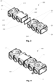
- FIG. 3 shows an exploded view of an air distributor assembly 100 according to an embodiment of the invention, which comprises two air distributor units 1 and 1', each according to any of the embodiments as described herein.
- the two air distributor units 1 and 1' are adjacently connected, i.e. first end 23 of the first air distributor unit 1 is connected to second end 24' of the second air distributor unit 1'.
- sealing lip 102 is arranged between the two connected air distributor units 1 and 1'.
- the air distributor assembly consists of two air distributor units. While air distributor unit 1' comprises seven lateral connector openings (only 21 1', 212' and 213' are references for clarity purposes), air distributor unit 1 comprises eight lateral connector openings (not referenced for reasons of clarity).
- Fig. 4 shows the air distributor assembly 100 of Fig. 4 in the assembled state in a perspective view.
- the two air distributor units 1 and 1' are connected with each other via connecting element 101, which can be slided over the rear grips of the two units.
- the rear grips form together the male part of the form locking connection, which is fixed via form-locking by sliding connector element 101 over the two rear grips.
- the air distributor assembly 100 comprises foot 5 (for clarity reasons only a single foot is shown), which is mounted onto fastening structure 214' (see Fig. 3 ).
- Fig. 5 shows a bottom view of the air distributor assembly of Fig. 5 , which exemplifies how connector element 101 is slided over the two rear grips. Furthermore, it can be seen how first end 23 of first air distributor unit 1 and second end 24' of second air distributor unit 1' are directly adjacently connected with each other.
- Fig. 6 an enlarged view of section A is shown, which shows rear grips 31 and 41' of the first air distributor unit 1, respectively of second air distributor unit 1'.
Landscapes
- Engineering & Computer Science (AREA)
- General Engineering & Computer Science (AREA)
- Mechanical Engineering (AREA)
- Chemical & Material Sciences (AREA)
- Combustion & Propulsion (AREA)
- Manufacturing & Machinery (AREA)
- Quick-Acting Or Multi-Walled Pipe Joints (AREA)
Claims (14)
- Luftverteilereinheit (1), umfassenda. einen rohrförmigen Grundkörper (2) mit einer einen Innenraum (22) umschließenden äußeren Seitenwand (21), wobei der rohrförmige Grundkörper (2) aus einem Polymermaterial hergestellt ist und sich in Längsrichtung der Luftverteilereinheit zwischen einem ersten Ende (23) und einem zweiten Ende (24) erstreckt, und am ersten Ende eine erste Öffnung (25) und am zweiten Ende eine zweite Öffnung (26) umfasst, wobei der rohrförmige Grundkörper (2) spritzgegossen und als einteiliger rohrförmiger Grundkörper ausgebildet ist;b. wobei die offene Querschnittsfläche der ersten Öffnung (25) und die offene Querschnittsfläche der zweiten Öffnung (26) jeweils größer ist als die innere Querschnittsfläche der äußeren Seitenwand (21) des rohrförmigen Grundkörpers (2) zwischen dem ersten Ende (23) und dem zweiten Ende (24) des rohrförmigen Grundkörpers, dadurch gekennzeichnet, dass der rohrförmige Grundkörper (2) einen ersten Flansch (3) um die erste Öffnung (25) und einen zweiten Flansch (4) um die zweite Öffnung (26) umfasst.
- Die Luftverteilereinheit (1) nach Anspruch 1, wobei die äußere Seitenwand (21) mindestens eine laterale Anschlussöffnung (211, 212, 213) in den Innenraum (22) umfasst.
- Die Luftverteilereinheit (1) nach Anspruch 1 oder 2, wobei die äußere Seitenwand (21) einen austauschbaren Wandabschnitt umfasst, der vorzugsweise eine laterale Anschlussöffnung (211, 212, 213) in den Innenraum (22) umfasst.
- Die Luftverteilereinheit (1) nach Anspruch 2 oder 3, wobei die äußere Seitenwand (21) eine Vielzahl von Wandebenen umfasst, die den Innenraum umschließen und zueinander abgewinkelt sind, und wobei die äußere Seitenwand mindestens zwei laterale Anschlussöffnungen (211, 212, 213) innerhalb unterschiedlicher Wandebenen und/oder innerhalb der gleichen Wandebene umfasst.
- Die Luftverteilereinheit (1) nach einem der vorhergehenden Ansprüche, wobei der erste Flansch (3) und der zweite Flansch (4) jeweils mindestens eine Faltkante (31, 41) umfassen, die einen Hinterschnitt definiert.
- Die Luftverteilereinheit (1) nach einem der vorhergehenden Ansprüche, wobei der rohrförmige Grundkörper (2) am ersten Ende (23) und am zweiten Ende (24) seiner Stirnseiten vorstehende Zähne (241) und Vertiefungen (242) zur Aufnahme eines Zahns umfasst; und/oder wobei der rohrförmige Grundkörper (2) am ersten Ende (23) und am zweiten Ende (24) seiner Stirnseiten jeweils eine Nut (243) umfasst, die umlaufend um die erste Öffnung (25) oder die zweite Öffnung (26) angeordnet ist und zur Aufnahme einer Dichtlippe ausgebildet ist.
- Die Luftverteilereinheit (1) nach einem der vorhergehenden Ansprüche, ferner umfassend eine männliche Verbindungsstruktur, die umlaufend um die erste Öffnung (25) angeordnet ist, und eine weibliche Verbindungsstruktur, die umlaufend um die zweite Öffnung (26) angeordnet ist.
- Die Luftverteilereinheit (1) nach einem der vorhergehenden Ansprüche, wobei die äußere Seitenwand (21) mindestens eine Befestigungsstruktur (214) zur Befestigung mindestens eines Stützbein umfasst, wobei vorzugsweise die Befestigungsstruktur (214) zur Herstellung einer Schnapp- oder Rastverbindung mit dem mindestens einen Stützbein ausgebildet ist.
- Die Luftverteilereinheit (1) nach Anspruch 8, wobei die Befestigungsstruktur (214) so ausgebildet ist, dass das mindestens eine Stützbein auf einer Vielzahl von unterschiedlichen Stufen befestigt werden kann.
- Die Luftverteilereinheit (1) nach einem der vorhergehenden Ansprüche, wobei die Luftverteilereinheit (1) ferner eine Vielzahl von Füßen (5) umfasst, die aus dem rohrförmigen Grundkörper (2) herausragen, wobei vorzugsweise jeder der Füße (5) ausziehbar ist.
- Die Luftverteilereinheit (1) nach einem der vorhergehenden Ansprüche, wobei die äußere Seitenwand (21) eine erste Neigung (215), insbesondere eine erste lineare Neigung, umfasst, die sich von der ersten Öffnung (23) zu einer Engstelle (6) erstreckt, und eine zweite Neigung (216), insbesondere eine zweite lineare Neigung, die sich von der zweiten Öffnung (26) zu der Engstelle (6) erstreckt, wobei die Engstelle (6) zwischen der ersten Öffnung (25) und der zweiten Öffnung (26) angeordnet ist.
- Die Luftverteilereinheit (1) nach Anspruch 11, wobei die erste lineare Neigung (215) und die zweite lineare Neigung (216) jeweils einen Neigungswinkel bezüglich der Längsrichtung von 0,5° bis 6°, insbesondere von 1 ° bis 5°, umfassen.
- Bausatz umfassend mindestens zwei Luftverteilereinheiten (1, 1') jeweils nach einem der vorhergehenden Ansprüche, eine oder mehrere Dichtlippen (102), die zur Abdichtung zwischen zwei benachbart verbundenen Luftverteilereinheiten (1, 1') ausgebildet sind, und optional eine Vielzahl von Verbindungselementen (101), wobei vorzugsweise die Verbindungselemente (101) zur Verbindung zweier benachbarter Luftverteilereinheiten (1, 1') über eine formschlüssige Verbindung ausgebildet sind; wobei vorzugsweise der Bausatz ferner eine Vielzahl von Stützbeinen und/oder Füßen (5) umfasst, die vorzugsweise so konfiguriert sind, dass sie an der mindestens einen Befestigungsstruktur (214) befestigt werden können.
- Eine Luftverteilerbaugruppe (100) umfassend mindestens zwei benachbart verbundene Luftverteilereinheiten (1, 1') nach einem der Ansprüche 1 bis 12, wobei die erste Öffnung der einen Luftverteilereinheit (1) mit der zweiten Öffnung der anderen Luftverteilereinheit (1') verbunden ist, wobei zwischen den beiden verbundenen Luftverteilereinheiten (1, 1') eine Dichtlippe angeordnet ist, wobei vorzugsweise die beiden Luftverteilereinheiten (1, 1') durch mindestens ein Verbindungselement (101), vorzugsweise über eine formschlüssige Verbindung, verbunden sind.
Applications Claiming Priority (1)
| Application Number | Priority Date | Filing Date | Title |
|---|---|---|---|
| CH5612021 | 2021-05-19 |
Publications (3)
| Publication Number | Publication Date |
|---|---|
| EP4092348A1 EP4092348A1 (de) | 2022-11-23 |
| EP4092348B1 true EP4092348B1 (de) | 2024-11-20 |
| EP4092348C0 EP4092348C0 (de) | 2024-11-20 |
Family
ID=81654555
Family Applications (1)
| Application Number | Title | Priority Date | Filing Date |
|---|---|---|---|
| EP22173575.6A Active EP4092348B1 (de) | 2021-05-19 | 2022-05-16 | Luftverteilereinheit |
Country Status (1)
| Country | Link |
|---|---|
| EP (1) | EP4092348B1 (de) |
Families Citing this family (1)
| Publication number | Priority date | Publication date | Assignee | Title |
|---|---|---|---|---|
| WO2025119564A1 (de) * | 2023-12-05 | 2025-06-12 | Voss Automotive Gmbh | Modulares fluidverteilersystem |
Citations (1)
| Publication number | Priority date | Publication date | Assignee | Title |
|---|---|---|---|---|
| US5954371A (en) * | 1996-04-26 | 1999-09-21 | Crane Co. | Plastic lined fittings for use with flangeless piping systems |
Family Cites Families (9)
| Publication number | Priority date | Publication date | Assignee | Title |
|---|---|---|---|---|
| AU630256B2 (en) * | 1986-10-17 | 1992-10-22 | Ductair Pty Ltd | Improvements relating to airconditioning ducting |
| US6676173B2 (en) * | 2001-11-26 | 2004-01-13 | Talana Investments Limited | Duct joiner and method of manufacture |
| KR100838891B1 (ko) * | 2003-06-25 | 2008-06-16 | 엘지전자 주식회사 | 환기시스템 |
| US6843274B1 (en) * | 2003-06-25 | 2005-01-18 | Air Systems International, Inc. | Electrically conductive confined space ventilator conduit formed of conductive polymer, electrical grounding circuit for ventilation system using same, and methods of using and forming same |
| KR100796230B1 (ko) * | 2006-09-05 | 2008-01-21 | 주식회사 프럼파스트 | 닥트내 공기량의 조절 및 유도장치 |
| PL2504631T3 (pl) * | 2009-11-24 | 2019-09-30 | Climate Recovery Ind Ab | Element łączący i sposób jego wytwarzania |
| EP2479508B1 (de) * | 2011-01-21 | 2016-10-12 | STIEBEL ELTRON GmbH & Co. KG | Luftverteilungssystem |
| GB201207715D0 (en) * | 2012-05-02 | 2012-06-13 | Nuaire Ltd | A ventilation apparatus |
| WO2017182867A1 (de) * | 2016-04-18 | 2017-10-26 | Zehnder Group International Ag | Luftführungsbausatz für eine lüftungsanlage sowie lüftungsanlage mit einem derartigen lüftungsbausatz |
-
2022
- 2022-05-16 EP EP22173575.6A patent/EP4092348B1/de active Active
Patent Citations (1)
| Publication number | Priority date | Publication date | Assignee | Title |
|---|---|---|---|---|
| US5954371A (en) * | 1996-04-26 | 1999-09-21 | Crane Co. | Plastic lined fittings for use with flangeless piping systems |
Also Published As
| Publication number | Publication date |
|---|---|
| EP4092348A1 (de) | 2022-11-23 |
| EP4092348C0 (de) | 2024-11-20 |
Similar Documents
| Publication | Publication Date | Title |
|---|---|---|
| CA2776567C (en) | Drainage body | |
| FI94493B (fi) | Leikkikalurakennussarja | |
| EP4092348A1 (de) | Luftverteilereinheit | |
| US3884438A (en) | Plumbing structure | |
| US6722086B2 (en) | Modular structure system | |
| WO2004111513A1 (en) | System for sealing a space between a tubular opening and a tube | |
| GB2520756A (en) | Manifold | |
| US20150252570A1 (en) | Swivel connector | |
| KR101466494B1 (ko) | 지오데식 돔 | |
| US20110107696A1 (en) | Item of wall-like standing furniture | |
| US4484429A (en) | Connector for a framework structure | |
| WO2014006137A1 (en) | Irrigation box, drainage box, or an attenuation box and a set of two of these boxes | |
| ATE541099T1 (de) | Füll- und dämmelement und bausystem mit solch einem element | |
| KR20100009142A (ko) | 신장조절기능을 구비한 건축용 슬리브 | |
| AU2024201276B2 (en) | Formwork system | |
| US20040144327A1 (en) | Corner joint particularly for modular cages | |
| ES2999665T3 (en) | Air distributor unit | |
| US9145671B1 (en) | Modular housing framing systems | |
| ES2825081T3 (es) | Esquina de escalera portacables | |
| US8770883B1 (en) | Pivot connector for modular platform assemblies | |
| AU700016B2 (en) | Composite building unit | |
| EP0191956B1 (de) | Wärmetauscher | |
| KR200432432Y1 (ko) | 덕트 | |
| KR20090114536A (ko) | 흙을 이용한 수로관 | |
| KR101748783B1 (ko) | 조립 블록과 이를 이용한 아치형 하우스 구조물 |
Legal Events
| Date | Code | Title | Description |
|---|---|---|---|
| PUAI | Public reference made under article 153(3) epc to a published international application that has entered the european phase |
Free format text: ORIGINAL CODE: 0009012 |
|
| STAA | Information on the status of an ep patent application or granted ep patent |
Free format text: STATUS: THE APPLICATION HAS BEEN PUBLISHED |
|
| AK | Designated contracting states |
Kind code of ref document: A1 Designated state(s): AL AT BE BG CH CY CZ DE DK EE ES FI FR GB GR HR HU IE IS IT LI LT LU LV MC MK MT NL NO PL PT RO RS SE SI SK SM TR |
|
| STAA | Information on the status of an ep patent application or granted ep patent |
Free format text: STATUS: REQUEST FOR EXAMINATION WAS MADE |
|
| 17P | Request for examination filed |
Effective date: 20221129 |
|
| RBV | Designated contracting states (corrected) |
Designated state(s): AL AT BE BG CH CY CZ DE DK EE ES FI FR GB GR HR HU IE IS IT LI LT LU LV MC MK MT NL NO PL PT RO RS SE SI SK SM TR |
|
| STAA | Information on the status of an ep patent application or granted ep patent |
Free format text: STATUS: EXAMINATION IS IN PROGRESS |
|
| 17Q | First examination report despatched |
Effective date: 20230905 |
|
| REG | Reference to a national code |
Ref country code: DE Ref legal event code: R079 Ref document number: 602022007812 Country of ref document: DE Free format text: PREVIOUS MAIN CLASS: F24F0013020000 Ipc: F16L0009000000 |
|
| GRAP | Despatch of communication of intention to grant a patent |
Free format text: ORIGINAL CODE: EPIDOSNIGR1 |
|
| STAA | Information on the status of an ep patent application or granted ep patent |
Free format text: STATUS: GRANT OF PATENT IS INTENDED |
|
| RIC1 | Information provided on ipc code assigned before grant |
Ipc: F16L 41/03 20060101ALI20240619BHEP Ipc: F16L 23/14 20060101ALI20240619BHEP Ipc: F16L 23/04 20060101ALI20240619BHEP Ipc: F24F 13/02 20060101ALI20240619BHEP Ipc: F16L 11/00 20060101ALI20240619BHEP Ipc: F16L 9/00 20060101AFI20240619BHEP |
|
| INTG | Intention to grant announced |
Effective date: 20240704 |
|
| GRAS | Grant fee paid |
Free format text: ORIGINAL CODE: EPIDOSNIGR3 |
|
| GRAA | (expected) grant |
Free format text: ORIGINAL CODE: 0009210 |
|
| STAA | Information on the status of an ep patent application or granted ep patent |
Free format text: STATUS: THE PATENT HAS BEEN GRANTED |
|
| AK | Designated contracting states |
Kind code of ref document: B1 Designated state(s): AL AT BE BG CH CY CZ DE DK EE ES FI FR GB GR HR HU IE IS IT LI LT LU LV MC MK MT NL NO PL PT RO RS SE SI SK SM TR |
|
| REG | Reference to a national code |
Ref country code: GB Ref legal event code: FG4D |
|
| REG | Reference to a national code |
Ref country code: CH Ref legal event code: EP |
|
| REG | Reference to a national code |
Ref country code: DE Ref legal event code: R096 Ref document number: 602022007812 Country of ref document: DE |
|
| REG | Reference to a national code |
Ref country code: IE Ref legal event code: FG4D |
|
| U01 | Request for unitary effect filed |
Effective date: 20241122 |
|
| U07 | Unitary effect registered |
Designated state(s): AT BE BG DE DK EE FI FR IT LT LU LV MT NL PT RO SE SI Effective date: 20241129 |
|
| REG | Reference to a national code |
Ref country code: ES Ref legal event code: FG2A Ref document number: 2999665 Country of ref document: ES Kind code of ref document: T3 Effective date: 20250226 |
|
| PG25 | Lapsed in a contracting state [announced via postgrant information from national office to epo] |
Ref country code: IS Free format text: LAPSE BECAUSE OF FAILURE TO SUBMIT A TRANSLATION OF THE DESCRIPTION OR TO PAY THE FEE WITHIN THE PRESCRIBED TIME-LIMIT Effective date: 20250320 Ref country code: HR Free format text: LAPSE BECAUSE OF FAILURE TO SUBMIT A TRANSLATION OF THE DESCRIPTION OR TO PAY THE FEE WITHIN THE PRESCRIBED TIME-LIMIT Effective date: 20241120 |
|
| PG25 | Lapsed in a contracting state [announced via postgrant information from national office to epo] |
Ref country code: NO Free format text: LAPSE BECAUSE OF FAILURE TO SUBMIT A TRANSLATION OF THE DESCRIPTION OR TO PAY THE FEE WITHIN THE PRESCRIBED TIME-LIMIT Effective date: 20250220 |
|
| PG25 | Lapsed in a contracting state [announced via postgrant information from national office to epo] |
Ref country code: GR Free format text: LAPSE BECAUSE OF FAILURE TO SUBMIT A TRANSLATION OF THE DESCRIPTION OR TO PAY THE FEE WITHIN THE PRESCRIBED TIME-LIMIT Effective date: 20250221 |
|
| PG25 | Lapsed in a contracting state [announced via postgrant information from national office to epo] |
Ref country code: PL Free format text: LAPSE BECAUSE OF FAILURE TO SUBMIT A TRANSLATION OF THE DESCRIPTION OR TO PAY THE FEE WITHIN THE PRESCRIBED TIME-LIMIT Effective date: 20241120 |
|
| PG25 | Lapsed in a contracting state [announced via postgrant information from national office to epo] |
Ref country code: RS Free format text: LAPSE BECAUSE OF FAILURE TO SUBMIT A TRANSLATION OF THE DESCRIPTION OR TO PAY THE FEE WITHIN THE PRESCRIBED TIME-LIMIT Effective date: 20250220 |
|
| U20 | Renewal fee for the european patent with unitary effect paid |
Year of fee payment: 4 Effective date: 20250528 |
|
| PG25 | Lapsed in a contracting state [announced via postgrant information from national office to epo] |
Ref country code: SM Free format text: LAPSE BECAUSE OF FAILURE TO SUBMIT A TRANSLATION OF THE DESCRIPTION OR TO PAY THE FEE WITHIN THE PRESCRIBED TIME-LIMIT Effective date: 20241120 |
|
| PGFP | Annual fee paid to national office [announced via postgrant information from national office to epo] |
Ref country code: CH Payment date: 20250601 Year of fee payment: 4 |
|
| PG25 | Lapsed in a contracting state [announced via postgrant information from national office to epo] |
Ref country code: SK Free format text: LAPSE BECAUSE OF FAILURE TO SUBMIT A TRANSLATION OF THE DESCRIPTION OR TO PAY THE FEE WITHIN THE PRESCRIBED TIME-LIMIT Effective date: 20241120 |
|
| PG25 | Lapsed in a contracting state [announced via postgrant information from national office to epo] |
Ref country code: CZ Free format text: LAPSE BECAUSE OF FAILURE TO SUBMIT A TRANSLATION OF THE DESCRIPTION OR TO PAY THE FEE WITHIN THE PRESCRIBED TIME-LIMIT Effective date: 20241120 |
|
| PLBE | No opposition filed within time limit |
Free format text: ORIGINAL CODE: 0009261 |
|
| STAA | Information on the status of an ep patent application or granted ep patent |
Free format text: STATUS: NO OPPOSITION FILED WITHIN TIME LIMIT |
|
| PGFP | Annual fee paid to national office [announced via postgrant information from national office to epo] |
Ref country code: ES Payment date: 20250630 Year of fee payment: 4 |
|
| 26N | No opposition filed |
Effective date: 20250821 |
|
| PG25 | Lapsed in a contracting state [announced via postgrant information from national office to epo] |
Ref country code: MC Free format text: LAPSE BECAUSE OF FAILURE TO SUBMIT A TRANSLATION OF THE DESCRIPTION OR TO PAY THE FEE WITHIN THE PRESCRIBED TIME-LIMIT Effective date: 20241120 |
|
| PG25 | Lapsed in a contracting state [announced via postgrant information from national office to epo] |
Ref country code: IE Free format text: LAPSE BECAUSE OF NON-PAYMENT OF DUE FEES Effective date: 20250516 |