EP4092371A1 - Caloduc à performance améliorée sous diverses répartitions de charges thermiques - Google Patents
Caloduc à performance améliorée sous diverses répartitions de charges thermiques Download PDFInfo
- Publication number
- EP4092371A1 EP4092371A1 EP22174302.4A EP22174302A EP4092371A1 EP 4092371 A1 EP4092371 A1 EP 4092371A1 EP 22174302 A EP22174302 A EP 22174302A EP 4092371 A1 EP4092371 A1 EP 4092371A1
- Authority
- EP
- European Patent Office
- Prior art keywords
- heat pipe
- longitudinal
- circumferential
- channel
- channels
- Prior art date
- Legal status (The legal status is an assumption and is not a legal conclusion. Google has not performed a legal analysis and makes no representation as to the accuracy of the status listed.)
- Granted
Links
Images


Classifications
-
- F—MECHANICAL ENGINEERING; LIGHTING; HEATING; WEAPONS; BLASTING
- F28—HEAT EXCHANGE IN GENERAL
- F28D—HEAT-EXCHANGE APPARATUS, NOT PROVIDED FOR IN ANOTHER SUBCLASS, IN WHICH THE HEAT-EXCHANGE MEDIA DO NOT COME INTO DIRECT CONTACT
- F28D15/00—Heat-exchange apparatus with the intermediate heat-transfer medium in closed tubes passing into or through the conduit walls ; Heat-exchange apparatus employing intermediate heat-transfer medium or bodies
- F28D15/02—Heat-exchange apparatus with the intermediate heat-transfer medium in closed tubes passing into or through the conduit walls ; Heat-exchange apparatus employing intermediate heat-transfer medium or bodies in which the medium condenses and evaporates, e.g. heat pipes
- F28D15/0233—Heat-exchange apparatus with the intermediate heat-transfer medium in closed tubes passing into or through the conduit walls ; Heat-exchange apparatus employing intermediate heat-transfer medium or bodies in which the medium condenses and evaporates, e.g. heat pipes the conduits having a particular shape, e.g. non-circular cross-section, annular
-
- F—MECHANICAL ENGINEERING; LIGHTING; HEATING; WEAPONS; BLASTING
- F28—HEAT EXCHANGE IN GENERAL
- F28D—HEAT-EXCHANGE APPARATUS, NOT PROVIDED FOR IN ANOTHER SUBCLASS, IN WHICH THE HEAT-EXCHANGE MEDIA DO NOT COME INTO DIRECT CONTACT
- F28D15/00—Heat-exchange apparatus with the intermediate heat-transfer medium in closed tubes passing into or through the conduit walls ; Heat-exchange apparatus employing intermediate heat-transfer medium or bodies
- F28D15/02—Heat-exchange apparatus with the intermediate heat-transfer medium in closed tubes passing into or through the conduit walls ; Heat-exchange apparatus employing intermediate heat-transfer medium or bodies in which the medium condenses and evaporates, e.g. heat pipes
- F28D15/04—Heat-exchange apparatus with the intermediate heat-transfer medium in closed tubes passing into or through the conduit walls ; Heat-exchange apparatus employing intermediate heat-transfer medium or bodies in which the medium condenses and evaporates, e.g. heat pipes with tubes having a capillary structure
-
- F—MECHANICAL ENGINEERING; LIGHTING; HEATING; WEAPONS; BLASTING
- F28—HEAT EXCHANGE IN GENERAL
- F28D—HEAT-EXCHANGE APPARATUS, NOT PROVIDED FOR IN ANOTHER SUBCLASS, IN WHICH THE HEAT-EXCHANGE MEDIA DO NOT COME INTO DIRECT CONTACT
- F28D15/00—Heat-exchange apparatus with the intermediate heat-transfer medium in closed tubes passing into or through the conduit walls ; Heat-exchange apparatus employing intermediate heat-transfer medium or bodies
- F28D15/02—Heat-exchange apparatus with the intermediate heat-transfer medium in closed tubes passing into or through the conduit walls ; Heat-exchange apparatus employing intermediate heat-transfer medium or bodies in which the medium condenses and evaporates, e.g. heat pipes
- F28D15/0275—Arrangements for coupling heat-pipes together or with other structures, e.g. with base blocks; Heat pipe cores
-
- F—MECHANICAL ENGINEERING; LIGHTING; HEATING; WEAPONS; BLASTING
- F28—HEAT EXCHANGE IN GENERAL
- F28D—HEAT-EXCHANGE APPARATUS, NOT PROVIDED FOR IN ANOTHER SUBCLASS, IN WHICH THE HEAT-EXCHANGE MEDIA DO NOT COME INTO DIRECT CONTACT
- F28D15/00—Heat-exchange apparatus with the intermediate heat-transfer medium in closed tubes passing into or through the conduit walls ; Heat-exchange apparatus employing intermediate heat-transfer medium or bodies
- F28D15/02—Heat-exchange apparatus with the intermediate heat-transfer medium in closed tubes passing into or through the conduit walls ; Heat-exchange apparatus employing intermediate heat-transfer medium or bodies in which the medium condenses and evaporates, e.g. heat pipes
- F28D15/0283—Means for filling or sealing heat pipes
-
- F—MECHANICAL ENGINEERING; LIGHTING; HEATING; WEAPONS; BLASTING
- F28—HEAT EXCHANGE IN GENERAL
- F28D—HEAT-EXCHANGE APPARATUS, NOT PROVIDED FOR IN ANOTHER SUBCLASS, IN WHICH THE HEAT-EXCHANGE MEDIA DO NOT COME INTO DIRECT CONTACT
- F28D15/00—Heat-exchange apparatus with the intermediate heat-transfer medium in closed tubes passing into or through the conduit walls ; Heat-exchange apparatus employing intermediate heat-transfer medium or bodies
- F28D15/02—Heat-exchange apparatus with the intermediate heat-transfer medium in closed tubes passing into or through the conduit walls ; Heat-exchange apparatus employing intermediate heat-transfer medium or bodies in which the medium condenses and evaporates, e.g. heat pipes
- F28D15/04—Heat-exchange apparatus with the intermediate heat-transfer medium in closed tubes passing into or through the conduit walls ; Heat-exchange apparatus employing intermediate heat-transfer medium or bodies in which the medium condenses and evaporates, e.g. heat pipes with tubes having a capillary structure
- F28D15/046—Heat-exchange apparatus with the intermediate heat-transfer medium in closed tubes passing into or through the conduit walls ; Heat-exchange apparatus employing intermediate heat-transfer medium or bodies in which the medium condenses and evaporates, e.g. heat pipes with tubes having a capillary structure characterised by the material or the construction of the capillary structure
-
- F—MECHANICAL ENGINEERING; LIGHTING; HEATING; WEAPONS; BLASTING
- F28—HEAT EXCHANGE IN GENERAL
- F28F—DETAILS OF HEAT-EXCHANGE AND HEAT-TRANSFER APPARATUS, OF GENERAL APPLICATION
- F28F2220/00—Closure means, e.g. end caps on header boxes or plugs on conduits
Definitions
- the invention relates to heat pipes, heat transfer devices, in particular for cooling a heating member.
- a heat pipe generally comprises a central axial channel in which moves the working fluid in the form of vapor, and longitudinal grooves extending axially and around the central axial channel, intended to advance the working fluid in the form of liquid according to a direction opposite to that of the steam.
- the inventors have sought to improve this situation.
- the circumferential transfer channel makes it possible to make the neighboring grooves of the most stressed groove or grooves contribute to the liquid fluid supply function. Liquid passes through the circumferential transfer channel from a less stressed groove to a more stressed groove. This helps to push back the thermal load limits which could lead to partial or total drying out of one or more of the most stressed grooves.
- the most thermally stressed parts are those where the flow/flow rate of vaporization is the greatest.
- the longitudinal path (PX) can be rectilinear or not rectilinear. If the path is not rectilinear, the axial direction is therefore local and not an absolute direction.
- circumferential transfer channel (6) generally takes the form of an annular passage. In practice, it often appears as an annular groove.
- longitudinal channels are made as longitudinal grooves, generally obtained by extrusion and made in one piece with the main profiled body.
- the circumferential transfer channel can place all the longitudinal channels in fluid communication, to which the annular passage in fact makes a complete turn. But it is not excluded that in particular configurations with thermal loads known in advance, the circumferential transfer channel puts the longitudinal channels in fluid communication over half the circumference (a half-turn only) or over a or several arbitrary angular ranges.
- section of the longitudinal channels can have various possible shapes, the bottom not necessarily being flat, the low walls not necessarily being straight.
- the section of the longitudinal channels has a general concavity.
- the section of the longitudinal channels can generally be in the form of an arc of a circle or an arc of an oval.
- the section of the longitudinal channels can be trapezoidal.
- the circumferential transfer channel goes all the way around and puts all the longitudinal channels in fluid communication. This makes it possible to have a homogeneous and predictable behavior whatever the load distribution on the periphery of the heat pipe. Whatever the most thermally loaded part of the circumference, the most thermally stressed groove or grooves receive additional liquid from the other grooves via the circumferential transfer channel.
- circumferential transfer channels can be provided, arranged one after the other in the longitudinal direction.
- the liquid redistribution effect can be multiplied and the capillary pressure increased over an entire area.
- the circumferential transfer channel can be delimited radially inwards by a cover ring, the cover ring then being interposed between the circumferential transfer channel and the axial channel.
- the presence of the cover ring makes it possible to promote the formation of a liquid meniscus on its wall and the walls of adjacent low walls.
- the presence of the cover ring makes it possible to increase the capillary pressure at this axial position of the heat pipe.
- the design of the ring is optimized to limit the local pressure drops in the longitudinal flow, on the liquid or on the vapour.
- the circumferential channel can be arranged at an intermediate position, the low walls (2) being interrupted over a predefined length (L6) at this location.
- L6 a predefined length
- a circumferential channel in the intermediate position it can be produced as an annular passage by means of a material removal operation with a tool of revolution such as a centrifugal cutter, or by electro-erosion or another general machining technique.
- the material of the low walls (2) is preferably removed over a height (H6) of between 50% and 100% of the height (H2) of the low walls.
- a low wall flange at the location of the circumferential channel, there remains a low wall flange over a residual height (H7) of between 0% and 50% of the normal height (H2) of the low walls. Retaining a low wall sole makes it possible to keep longitudinal contact lines to channel the liquid by capillarity notwithstanding the presence of the circumferential transfer channel.
- the low walls can comprise a first bearing zone (B1) to receive a first longitudinal end of the cover ring (4) and a second bearing zone (B2) to receive a second longitudinal end of the cover ring .
- B1 first bearing zone
- B2 second bearing zone
- the cover ring (4) may comprise a central extra thickness (45) forming a radially outer shoulder received between the low walls at the location of the first and second bearing zones (B1, B2).
- the cover ring (4) can have a constant thickness and the first and second bearing zones are then formed as flats (14) set back from the top of the low walls.
- the ring is then a simple cylinder obtained by sawing a tube, a very inexpensive component.
- the cover ring (4) can be made of a deformable material, either in the elastic domain or in the plastic domain, so that the cover ring can be introduced from one end of the profiled body to the first and second bearing zones, so that in the target position the cover ring closes the circumferential transfer channel radially inward.
- the elastic force is released or a plastic force (deformation) is applied towards the outside to achieve the final positioning.
- the first position (P1) is chosen in the vicinity of an evaporation portion (71) of the heat pipe coupled to a hot source (81).
- the effect of the equalization of the pressures of the liquid phase in the longitudinal channels is optimized as close as possible to the zone where drying out under high thermal load should be avoided.
- the first position (P1) is an intermediate position on the longitudinal path. Said intermediate position being arbitrary on the longitudinal path, there is thus complete freedom to position the circumferential transfer channel (or the circumferential channels) as close as possible to the need.
- the first position (P1) is an end position on the longitudinal path. In this configuration, it is easier to remove material from the low walls to form the annular groove forming the transfer channel.
- the circumferential channel is formed in an end plug (5) fixed to one end of the profiled body.
- no recovery operation is carried out on the profiled body resulting from extrusion.
- the complexity of the shapes and the fixing is carried by the end cap.
- one or more other circumferential channels are provided on the route, at distinct axial positions different from the first position.
- the multiple positions can be determined advantageously according to the application or be regularly distributed in the longitudinal direction, over all or part of the heat pipe.
- the heat pipe can comprise a combination of circumferential channels, some arranged in the intermediate longitudinal position and some arranged in the end position. In other words, there is no incompatibility in having several circumferential channels of different types coexist.
- the heat pipe can comprise a combination of different types of circumferential channels.
- one can have annular channels (360°) on the condenser side but also partially annular channels ( ⁇ 360°) on the evaporator side. If the thermal loading is known, the circumferential channels can be adapted to optimize the thermal-hydraulic performance.
- a plurality of circumferential channels can be provided on the path, at regularly spaced axial positions (P2, P3, P4), with a predetermined pitch, for example every 300 mm. This makes it possible to equalize the pressures of the liquid phase in all the grooves at regular intervals along the heat pipe.
- one or more intersections may be provided along the path of the heat pipe, with two circumferential channels arranged on either side of each intersection. This minimizes the a priori harmful effect of the intersection from the point of view of the hydraulic continuity between the channels.
- the heat pipe can be presented as a three-dimensional object. It then extends in space in the three Cartesian dimensions and not only in one plane.
- a total freedom of design and configuration is thus obtained to respond perfectly to all possible applications.
- the proposed heat pipes are devoid of capillary porous material intended to ensure capillary pumping.
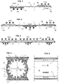
- FIG. 1 there is shown a heat pipe 1 which takes calories from a hot source 81 and rejects them towards a cold source 82.
- the hot source 81 is in contact with the heat pipe at the level of an evaporation portion 71.
- the cold source 82 is in contact with the heat pipe at a condensation portion 72.
- the heat pipe 1 takes the form of an elongated device closed at a first end 11 by a closing element 50 , and at a second end 12 by a second closing element 50 .
- the heat pipe receives calories from one side of the heat pipe axis (from below in the example shown) and rejects calories from the other side of the heat pipe axis (from below). above in the illustrated example).
- This is a configuration known in the trade as the “Heat Spreader”.
- the heat pipe 1 generally comprises a central axial channel 15 in which the working fluid moves in the form of vapor, and longitudinal grooves extending axially and around the central axial channel. As shown in figures 4 and 5 , the longitudinal grooves, also called longitudinal channels 3 are intended to advance the working fluid in liquid form in a direction opposite to that of the vapour.
- Heat pipe 1 is configured for use under low or no gravity.
- this type of heat pipe is used in machines and devices sent into space.
- this type of heat pipe is used in communication satellites, surveillance satellites, satellites having all types of other functions.
- the heat pipe 1 can be used in total weightlessness or in a situation of low gravity, for example on the surface of a celestial body such as the Moon or Mars.
- the heat pipe 1 can be used with zero or very low external pressure.
- the heat pipe 1 comprises a profiled body 10 obtained by extrusion. Complementary operations can be carried out as will be seen below. However, the extrusion operation is the main manufacturing operation. Thanks to a press, an aluminum alloy is pushed through a die having the desired shapes to obtain the profiled body at the outlet of the die.
- the profiled body forms a hollow body which delimits an interior space hermetically isolated from the external environment, and which will be used to contain the working fluid.
- the profiled body has a section which, after extrusion, extends identically along the longitudinal axis denoted X .
- the profiled body can then be bent, so that the finished heat pipe is not necessarily straight.
- the profiled body 10 extends along a longitudinal path PX .
- the longitudinal path PX can be straight or curved.
- the length of the PX course can be between 0.5 meters and 10 meters.
- the profiled body 10 comprises a peripheral tubular wall 75 , from which extend radially outwards, two feet 16 , 17 diametrically opposed. These feet each end in a support surface suitable for exchanging calories with the cold or hot source 82 , 81 .
- the body could have four interface planes, and in a particular case the outer boundary of the body could be substantially square or completely cylindrical.
- the thermal coupling elements could be separate and added, as illustrated in figure 16 .
- the profile is generally of revolution around the X axis, with inside a repetition of the pattern [groove + low wall] in the circumferential direction.
- the profiled body comprises a plurality of longitudinal channels 3 .
- the longitudinal channels are made as longitudinal grooves.
- Each of said longitudinal channels has a section delimited by a bottom 76 formed by a peripheral tubular wall 75 of the profiled body, and laterally by two longitudinal walls 2 which extend radially inwards from the peripheral tubular wall.
- the longitudinal channels surround the central axial channel 15 conveying steam.
- the longitudinal channels 3 generally are open towards the axial channel,
- the number of longitudinal channels is between 6 and 48.
- the longitudinal channels 3 are arranged annularly around the axis. However, non-circular arrangements are also possible.
- the peripheral tubular wall 75 has a pitch outer diameter D0.
- D0 can be between 3 millimeters and 50 millimeters.
- the diameter D1 represents the internal dimension of the peripheral tubular wall 75 , in other words the diameter taken at the bottom of the grooves.
- the diameter D2 represents the internal dimension of the axial channel, in other words the diameter of the circumscribed circle passing through the top 77 of the low walls.
- the interior space is perfectly hermetically isolated from the external environment, because the profile is one-piece and made of extrusion material, it surrounds the interior space with continuous material, without an orifice.
- the working fluid can be ammonia, propylene, methanol or any other medium having a liquid vapor equilibrium in saturation condition at the operating pressures defined by the temperature.
- a predetermined quantity of working fluid is introduced through one of the end elements equipped with a sealable filling orifice.
- the pressure prevailing in the interior space of the heat pipe can range from 0.1 bar up to several tens of bars.
- the predetermined quantity of working fluid is defined to preferably have a limited excess of liquid on the cold/condenser side, i.e. the grooves are totally filled and if necessary, fill the end of the axial channel, cold side.
- the section of the longitudinal channels 3 can have any suitable shape, the bottom 76 not necessarily being flat, the low walls not necessarily being straight.
- the section of the longitudinal channels has a general concavity.
- the cross-section of the longitudinal channels can generally be in the form of an arc of a circle or an arc of an oval, or even a drop shape open towards the channel.
- axial 15 In the example illustrated in the figures, the section appears as a trapezoidal section.
- At least one circumferential transfer channel 6 is provided, arranged transversely to the local axial direction.
- the circumferential transfer channel 6 is located at a first position P1 along the longitudinal path PX.
- the circumferential transfer channel 6 places all the longitudinal channels in fluid communication with one another. More generally The circumferential transfer channel 6 places all or part of the plurality of longitudinal channels in communication with each other.
- the circumferential transfer channel 6 generally takes the form of an annular passage. In practice, it often appears as an annular groove, which makes a complete ring (360°) without excluding a smaller angular opening.
- the longitudinal walls 2 are interrupted at the location of the circumferential channel 6 .
- the material from the low walls was removed to a depth of H6 .
- the circumferential transfer channel 6 has an axial length L6 .
- the axial length L6 of the circumferential channel can be, as in the example illustrated, greater than the height H2 of the grooves.
- the axial length L6 of the circumferential channel may be less than the height H2 of the grooves.
- H6 can be between 50% and 100% of the H2 height.
- H6 can be between 70% and 100% of the H2 height.
- circumferential transfer channels can be provided, arranged one after the other in the longitudinal direction X. Provision could be made to produce such a fairly tight succession of transverse channels of small longitudinal dimension (small L6 ).
- the circumferential transfer channel 6 is delimited radially inwards by a cover ring 4 .
- the cover ring 4 is interposed between the circumferential transfer channel and the axial channel.
- the cover ring 4 closes the circumferential transfer channel 6 radially towards the X axis.
- the cover ring 4 generally takes the form of a tubular body 40 , otherwise called a sleeve.
- the cover ring 4 has an axial length L5 .
- the axial length L5 of the cover ring is in practice chosen to be slightly greater than the axial length L6 of the circumferential channel.
- the radial thickness E5 of the cover ring, at the level of the circumferential transfer channel, is between 0.1 millimeter and 1 millimeter.
- the internal diameter of the ring is denoted D4.
- the external diameter of the ring at the level of the circumferential channel is denoted D5.
- the cover ring 4 can be made of a deformable material, either in the elastic domain or in the plastic domain, in order to be able to be installed in position to cover and radially close the circumferential channel 6.
- the ring is constrained radially inwards then it is inserted by threading inside the axial channel and once arrived at the correct axial position (target position), the elastic constraint is released , leading to expansion and final positioning.
- a first bearing zone B1 is arranged to receive a first longitudinal end 41 of the cover ring 4 and a second bearing zone B2 to receive a second longitudinal end 42 of the cover ring.
- the cover ring 4 may include a central extra thickness 45 forming a radially outer shoulder 47 .
- the central extra thickness 45 is received between the low walls on stop fronts 44 at the location of the first and second bearing zones.
- the cover ring has a constant thickness E4 and the first and second bearing zones B1, B2 are formed as flats 14 set back from the top of the low walls.
- the diameter D4 is greater than D2 , ie the ring is set back radially from the tops 77 of the low walls.
- the flats 14 are obtained by removing material.
- the cover ring forms an additional line of contact which increases the capillary pressure at the circumferential channel 6 .
- the capillary pressure at the level of the circumferential channel 6 is greater than the capillary pressure along the longitudinal channels 3.
- the ring allows the total recovery of the hydraulic section at the level of the circumferential channel to ensure the continuity of the liquid flow.
- closing elements 50 which simply close the profiled body.
- the present invention provides for using the closing elements in a clever way.
- the circumferential channel is formed in an end plug 5 fixed to one end of the profiled body.
- the plug comprises an inner sleeve 51 and a closure disc 52 .
- a closure disc 52 We just weld / seal the disc on the end of the profiled body 10 at a seal 53 hermetic solid fixing.
- Closing disc 52 is thick enough to resist internal pressure.
- the inner sleeve 51 does not support any substantial force, and it is sufficient for the axial length L65 of the sleeve to be greater than the axial length L6 of the circumferential channel, to come flush with the tops 77 of the low walls 2.
- the circumferential channel 6 is obtained by removing material from the low walls on their end portion. This machining is relatively standard, it suffices to introduce a cutter with the prescribed diameter axially into the end portion of the body 10 .
- the stopper comprises an inner sleeve 51.
- the inner sleeve 51 can be separate from the closure disc 52 or else produced according to a one-piece logic. When it is separate, the inner sleeve 51 is received in a circular housing 57 in the bottom of the closing disc, and is presented as an easy-to-obtain piece: a simple tubular sleeve.
- a tight seal 53 is provided which connects the outer shell 54 of the cap 5 to the profiled body 10.
- the longitudinal walls 2 are interrupted at the location of the circumferential channel.
- the outer boundary of the circumferential channel is formed by a thickness 56 of the plug projecting radially inward.
- the first position P1 for the circumferential transfer channel is chosen in the vicinity of an evaporation portion 71 of the heat pipe coupled to a hot source.
- the circumferential transfer channel is filled with liquid and the pressure differences of the various grooves are equalized at this point.
- Menisci M are formed in the longitudinal channels, they are all the more hollowed out as the pressure difference is significant over the length of the groove, in particular in the longitudinal direction, between the cold sources corresponding to the lowest pressures and the hot sources. corresponding to the highest pressures.
- a meniscus forms in the circumferential transfer channel, which allows liquid to move in a circumferential direction and to transit from one longitudinal channel to another.
- FIG. 14A illustrates the ring as much as the bottom of the longitudinal channel initiate a meniscus.
- the Figure 14B illustrates the steady state where the entire volume of the circumferential transfer channel is filled with liquid.
- the meniscus is formed in the circumferential channel only transiently, and in steady state, it is the meniscuses of the longitudinal channels, deeper downstream than upstream, which generate the flow in the circumferential groove.
- the recirculation groove is designed to have greater capillary pumping than the longitudinal groove to properly prime liquid.
- the channel C1 is the most thermally stressed, it receives the calories via a short conductive path, it is at this point that the vaporization rate is the highest.
- the neighboring channels C2, CG also participate in vaporization, but slightly less.
- the slightly more distant channels C2, CG and following participate a little less in the vaporization, depending on the intensity of the heat flux, until they no longer participate at all in the vaporization for the furthest grooves, when all incoming flow was vaporized.
- the presence of a circumferential transfer channel close to the heat source makes it possible to convey towards the channel C1 the liquid which has not arrived via C1 over its length. In other words, the neighboring channels supply liquid to the first channel C1.
- channels CG, C1, C2 will be fed by all the other channels, ie C3, C4, C5, C6, C7, C8, C9, CA, CB, CC, CD, CE, CF.
- the circumferential transfer channel has a function of pooling and sharing the liquid supply. It supplies the most demanding longitudinal channel 3 with liquid, from the other channels.
- the closure ring promotes the supply of liquid to the circumferential transfer channel.
- the ring also favors the passage in a straight line in a particular longitudinal channel.
- closure ring is slightly set back from the top of the low walls, it has a favorable effect on the straight-line passage of the liquid in a longitudinal channel.
- one or more other circumferential channels are provided along the route, at distinct axial positions (P2, P3, P4) (P2) different from the first position.
- the path PX can include one or more curves 18, and if necessary can even include one or more right angles 19.
- the figure 19 represents a longitudinal half-section of the heat pipe in the vicinity of a connection at right angles with 2 circumferential transfer channels.
- two profiled bodies cut at 45° have been butted to form a right angle at this point; there is an imbalance of meniscus formation between the well-irrigated outer grooves and the rather dry inner grooves.
- the presence of one or two circumferential transfer channels near the corner makes it possible to equalize the pressures between the various longitudinal channels.
- the figure 20 represents a longitudinal half-section of the heat pipe in the vicinity of a cross connection with 4 circumferential transfer channels. This configuration is an extrapolation of the previous case illustrated in figure 19 , with four profiles butted at a cross intersection. The presence of the four circumferential channels in the vicinity of the intersection makes it possible to equalize the pressures between the various longitudinal channels.
- L6 being between 0.1 D0 and 0.5 D0.
- a value of between 0.05 D1 and 0.2 D1 can be chosen for H2 .
Landscapes
- Engineering & Computer Science (AREA)
- Life Sciences & Earth Sciences (AREA)
- Sustainable Development (AREA)
- Physics & Mathematics (AREA)
- Thermal Sciences (AREA)
- Mechanical Engineering (AREA)
- General Engineering & Computer Science (AREA)
- Heat-Exchange Devices With Radiators And Conduit Assemblies (AREA)
- Rigid Pipes And Flexible Pipes (AREA)
Abstract
Description
- L'invention concerne les caloducs, appareils de transfert thermique, notamment pour le refroidissement d'un organe chauffant.
- Un caloduc comprend généralement un canal axial central dans lequel se déplace du fluide de travail sous forme de vapeur, et des rainures longitudinales s'étendant axialement et autour du canal axial central, destinées à faire avancer le fluide de travail sous forme de liquide selon une direction opposée à celle de la vapeur.
- Dans le cas d'une charge thermique non régulièrement répartie autour du caloduc, les rainures travaillent de manière très différenciée et les rainures les plus sollicitées peuvent s'assécher alors que les autres ne travaillent que faiblement. Ce phénomène peut également être la conséquence d'une répartition inégale et évolutive des sources chaudes et froides le long du caloducs, comme c'est fréquemment le cas dans un grand nombre de cas d'application des caloducs (réseaux de caloducs, étalement de chaleur sur les radiateurs, uniformisation de la température sur une surface relativement grande, etc ...)
- Ce constat amène en pratique à surdimensionner le caloduc pour éviter un assèchement de rainure dans le cas d'un chargement thermique non régulièrement réparti, voire qui peut évoluer avec le temps.
- Les inventeurs ont cherché à améliorer cette situation.
- A cet effet, il est proposé un caloduc (1) configuré pour être utilisé sous gravité faible ou nulle, comprenant un corps profilé (10) obtenu généralement par extrusion, ledit corps profilé s'étendant le long d'un parcours longitudinal (PX), ledit corps profilé formant un corps creux fermé à au moins deux extrémités par des éléments de fermeture, formant ainsi un espace intérieur isolé hermétiquement de l'environnement extérieur, et empli d'un volume prédéfini de fluide de travail diphasique,
- ledit corps profilé comprenant une pluralité de canaux longitudinaux (3) (réalisés en pratique comme des rainures longitudinales), chacun desdits canaux ayant une section délimitée par un fond (76) formé par une paroi tubulaire périphérique (75) du corps profilé, et latéralement par deux murets longitudinaux (2) qui s'étendent radialement vers l'intérieur depuis la paroi tubulaire périphérique, les canaux longitudinaux entourant un canal axial (15) (convoyant de la vapeur), les canaux longitudinaux étant ouverts en direction du canal axial,
- caractérisé en ce qu'il est prévu, à au moins une première position (P1) le long du parcours longitudinal (PX), un canal circonférentiel de transfert (6), agencé transversalement à la direction axiale locale (X), et mettant en communication fluide tout ou partie de la pluralité des canaux longitudinaux entre eux, et en ce que les murets longitudinaux sont interrompus, partiellement ou totalement, à l'endroit du canal circonférentiel.
- Grâce à ces dispositions, le canal circonférentiel de transfert permet de faire contribuer les rainures voisines de la ou des rainures les plus sollicitées, pour la fonction d'alimentation en fluide liquide. Du liquide transite par le canal circonférentiel de transfert depuis une rainure moins sollicitée vers une rainure plus sollicitée. On contribue ainsi à repousser les limites de charge thermique qui pourraient conduire à un assèchement partiel ou total d'une ou plusieurs rainures, les plus sollicitées. Les parties les plus sollicitées thermiquement sont celles où le flux/débit de vaporisation est le plus important.
- Il faut noter que le parcours longitudinal (PX) peut être rectiligne ou non rectiligne. Si le parcours n'est pas rectiligne, la direction axiale est donc locale et non une direction absolue.
- Il faut noter que le canal circonférentiel de transfert (6) se présente généralement comme un passage annulaire. En pratique, il se présente souvent comme une gorge annulaire.
- Il faut noter que les canaux longitudinaux sont réalisés comme des rainures longitudinales, obtenues généralement par extrusion et venues de matière avec le corps profilé principal.
- Il faut noter que le canal circonférentiel de transfert peut mettre en communication fluide tous les canaux longitudinaux, auquel le passage annulaire fait en effet un tour complet. Mais il n'est pas exclu que dans des configurations particulières avec des charges thermiques connues à l'avance, le canal circonférentiel de transfert mette en communication fluide les canaux longitudinaux sur la moitié de la circonférence (un demi-tour seulement) ou sur une ou plusieurs plages angulaires quelconques.
- Il faut noter que la section des canaux longitudinaux peut présenter diverses formes possibles, le fond n'étant pas forcément plat, les murets n'étant pas forcément droits. Dans un exemple particulier la section des canaux longitudinaux présente une concavité générale. Dans un exemple particulier la section des canaux longitudinaux peut être généralement en arc de cercle ou en arc d'ovale. Dans un exemple particulier, la section des canaux longitudinaux peut être trapézoïdale.
- Dans divers modes de réalisation de l'invention concernant le procédé, on peut éventuellement avoir recours en outre à l'une et/ou à l'autre des dispositions suivantes, prises isolément ou en combinaison.
- Selon une option, le canal circonférentiel de transfert fait tout le tour et met en communication fluide tous les canaux longitudinaux. Ceci permet d'avoir un comportement homogène et prédictible quelle que soit la répartition de chargement sur le pourtour du caloduc. Quelle que soit la partie la plus chargée thermiquement de la circonférence, la ou les rainures les plus sollicitées thermiquement reçoivent du liquide complémentaire en provenance des autres rainures via le canal circonférentiel de transfert.
- Selon une option, on peut prévoir plusieurs canaux circonférentiels de transfert, agencés les uns à la suite des autres dans le sens longitudinal. Moyennant quoi, on peut multiplier l'effet de redistribution de liquide et augmenter la pression capillaire sur toute une zone.
- Selon une option, selon des dimensions particulières de rainure, en particulier des rainures circonférentielles fines par exemple, on peut se passer de la bague de couverture dont il est question juste après ici.
- Selon une option, le canal circonférentiel de transfert peut être délimité radialement vers l'intérieur par une bague de couverture, la bague de couverture étant alors interposée entre le canal circonférentiel de transfert et le canal axial. Avantageusement, la présence de la bague de couverture permet de favoriser la formation de ménisque de liquide sur sa paroi et les parois de murets adjacents. La présence de la bague de couverture permet d'augmenter la pression capillaire à cette position axiale du caloduc. Avantageusement, la conception de la bague est optimisée pour limiter les pertes de charges locales dans l'écoulement longitudinal, sur le liquide ou sur la vapeur.
- Selon une option, le canal circonférentiel peut être agencé à une position intermédiaire, les murets (2) étant interrompus sur une longueur (L6) prédéfinie à cet endroit. Ainsi, pour un canal circonférentiel en position intermédiaire, on peut le réaliser comme passage annulaire moyennant une opération d'enlèvement de matière avec un outil de révolution comme une fraise centrifuge, ou par électro-érosion ou autre technique générale d'usinage.
- Selon une option, à l'endroit du canal circonférentiel, la matière des murets (2) est enlevée de préférence sur une hauteur (H6) comprise entre 50% et 100% de la hauteur (H2) des murets.
- Selon une option, à l'endroit du canal circonférentiel, il reste une semelle de muret sur une hauteur résiduelle (H7) comprise entre 0% et 50% de la hauteur normale (H2) des murets. La conservation d'une semelle de muret permet de garder des lignes de contact longitudinales pour canaliser le liquide par capillarité nonobstant la présence du canal circonférentiel de transfert.
- Selon une option, les murets peuvent comprendre une première zone de portée (B1) pour recevoir une première extrémité longitudinale de la bague de couverture (4) et une deuxième zone de portée (B2) pour recevoir une deuxième extrémité longitudinale de la bague de couverture. Moyennant quoi la bague est maintenue bien en place sur les zones de portée par rapport aux murets, de part et d'autre du canal circonférentiel de transfert.
- Selon une option, la bague de couverture (4) peut comprendre une surépaisseur centrale (45) formant un épaulement radialement extérieur reçu entre les murets à l'endroit des première et deuxième zones de portée (B1 ,B2). Ceci est une solution simple et robuste, car en effet l'usinage de la gorge annulaire est relativement simple à réaliser et on peut obtenir une telle bague avec surépaisseur par tournage/décolletage standard.
- Selon une option, la bague de couverture (4) peut avoir une épaisseur constante et les première et deuxième zones de portée sont alors formées comme des méplats (14) en retrait du sommet des murets. Moyennant l'utilisation d'une fraise adaptée ou de deux passes d'usinage pour former le canal circonférentiel, la bague est alors un simple cylindre obtenu par sciage d'un tube, composant très bon marché.
- Selon une option, la bague de couverture (4) peut être réalisée dans un matériau déformable, soit dans le domaine élastique soit dans le domaine plastique, de manière que la bague de couverture peut être introduite depuis une extrémité du corps profilé jusqu'aux première et deuxième zones de portée, de sorte qu'en position cible la bague de couverture ferme le canal circonférentiel de transfert radialement vers l'intérieur. A la position cible, on relâche l'effort élastique ou on pratique un effort plastique (déformation) vers l'extérieur pour réaliser le positionnement définitif.
- Selon une option, la première position (P1) est choisie au voisinage d'une portion d'évaporation (71) du caloduc couplé à une source chaude (81). Ainsi on optimise l'effet de l'égalisation des pressions de la phase liquide dans les canaux longitudinaux au plus près de la zone où il convient d'éviter l'assèchement sous forte charge thermique.
- Selon une option, la première position (P1) est une position intermédiaire sur le parcours longitudinal. Ladite position intermédiaire étant quelconque sur le parcours longitudinal, on a ainsi toute liberté de positionner le canal circonférentiel de transfert (ou les canaux circonférentiels) au plus près du besoin.
- Selon une option, la première position (P1) est une position d'extrémité sur le parcours longitudinal. Dans cette configuration, il est plus aisé d'enlever de la matière sur les murets pour former la gorge annulaire formant le canal de transfert.
- Selon une option, le canal circonférentiel est formé dans un bouchon d'extrémité (5) fixé à une extrémité du corps profilé. Dans cette configuration, on ne pratique aucune opération de reprise sur le corps profilé issu d'extrusion. La complexité des formes et de la fixation est portée par le bouchon d'extrémité.
- Selon une option, il est prévu un ou plusieurs autres canaux circonférentiels sur le parcours, à des positions axiales distinctes et différentes de la première position. Les multiples positions peuvent être déterminées avantageusement en fonction de l'application ou être réparties régulièrement dans le sens longitudinal, sur la totalité ou une partie du caloduc.
- Selon une option, le caloduc peut comprendre une combinaison de canaux circonférentiels, certains agencés en position longitudinale intermédiaire et certains agencés en position d'extrémité. Autrement dit, il n'y a pas d'incompatibilité à faire coexister plusieurs canaux circonférentiels de type différent.
- Selon une option, le caloduc peut comprendre une combinaison de différents types de canaux circonférentiels. Par exemple on peut avoir des canaux annulaires (360°) du côté du condenseur mais aussi des canaux partiellement annulaires (<360°) du côté de l'évaporateur. Si le chargement thermique est connu on peut adapter les canaux circonférentiels pour optimiser les performances thermo-hydrauliques.
- Selon une option, il peut être prévu une pluralité de canaux circonférentiels sur le parcours, à des positions (P2,P3,P4) axiales régulièrement espacées, avec un pas prédéterminé, par exemple tous les 300 mm. Ceci permet d'égaliser les pressions de la phase liquide dans toutes les rainures à intervalles réguliers le long du caloduc.
- Selon une option, il peut être prévu sur le parcours du caloduc, une ou plusieurs intersections, avec deux canaux circonférentiels agencés de part et d'autre de chaque intersection. Ainsi on minimise l'effet a priori néfaste de l'intersection du point de vue de la continuité hydraulique entre les canaux.
- Selon une option, le caloduc peut se présenter comme un objet en trois dimensions. Il s'étend en alors dans l'espace dans les trois dimensions cartésiennes et pas seulement dans un plan. Avantageusement on obtient ainsi une liberté totale de design et configuration pour répondre parfaitement à toutes les applications possibles.
- Avantageusement dans les solutions proposées, il n'y a pas de couche poreuse, de masse poreuse, ou de revêtement poreux dans les caloducs proposés, ni ponctuellement ni généralement sur la longueur du caloduc. Dit autrement, les caloducs proposés sont dépourvus de matériau poreux capillaire destiné à assurer un pompage capillaire.
- D'autres aspects, buts et avantages de l'invention apparaîtront à la lecture de la description suivante d'un mode de réalisation de l'invention, donné à titre d'exemple non limitatif. L'invention sera également mieux comprise en regard des dessins joints sur lesquels :
- La
figure 1 représente schématiquement un caloduc couplé à une source chaude d'un côté et à une source froide du côté opposé. - La
figure 2 représente schématiquement un caloduc couplé à une source chaude dans une position intermédiaire d'un côté et couplé à 2 sources froides aux extrémités. - La
figure 3 représente schématiquement un caloduc couplé à une source froide continue sur la longueur, en partie supérieure du caloduc, et couplé à des sources chaudes en partie inférieure du caloduc, dans une configuration dite 'Heat Spreader'. - La
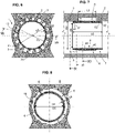
figure 4 représente une section transversale générale du corps profilé selon un mode de réalisation, selon la ligne de coupe IV illustrée à lafigure 7 . - La
figure 5 représente une section longitudinale du corps profilé. - La
figure 6 montre une section transversale du caloduc au voisinage du canal circonférentiel de transfert, selon la ligne de coupe VI illustrée à lafigure 7 . - La
figure 7 représente une section longitudinale du caloduc à l'endroit du canal circonférentiel de transfert. - La
figure 8 montre une section transversale du caloduc à l'endroit du canal circonférentiel de transfert, selon la ligne de coupe VIII illustrée à lafigure 7 . - La
figure 9 représente une demi-coupe longitudinale du caloduc à l'endroit du canal circonférentiel de transfert. - La
figure 10 est analogue à lafigure 7 et représente pour une variante de réalisation, une section longitudinale du caloduc à l'endroit du canal circonférentiel de transfert. - La
figure 11 montre une section transversale du caloduc, selon la ligne de coupe XI illustrée à lafigure 12 . - La
figure 12 représente une section longitudinale du caloduc au voisinage d'une extrémité avec un bouchon rapporté, selon la ligne de coupe XII illustrée à lafigure 11 . - La
figure 13 déclinée selon lesfigures 13A,13B,13C représente diverses formes du ménisque de la phase liquide du fluide de travail à l'intérieur d'un canal longitudinal. - La
figure 14 déclinée selon lesfigures 14A,14B représente diverses formes du ménisque de la phase liquide du fluide de travail à l'intérieur du canal circonférentiel de transfert. - La
figure 15 représente, dans une variante de réalisation, une section longitudinale du caloduc au voisinage d'une extrémité, avec un bouchon rapporté. - La
figure 16 représente une section transversale du corps profilé selon un second mode de réalisation. - La
figure 17 illustre plus en détail un exemple de géométrie du canal longitudinal et des murets qui le bordent. - La
figure 18 illustre l'exemple de parcours général d'un caloduc dans lequel l'invention peut être mise en œuvre. - La
figure 19 représente une demi-coupe longitudinale du caloduc au voisinage d'un raccordement à angle droit avec 2 canaux circonférentiels de transfert. - La
figure 20 représente une demi-coupe longitudinale du caloduc au voisinage d'un raccordement en croix avec 4 canaux circonférentiels de transfert. - Sur les différentes figures, les mêmes références désignent des éléments identiques ou similaires. Pour des raisons de clarté de l'exposé, certains éléments ne sont pas nécessairement représentés à l'échelle.
- Sur la
figure 1 , il est représenté un caloduc 1 qui prélève des calories depuis une source chaude 81 et les rejette vers une source froide 82. La source chaude 81 est en contact avec le caloduc au niveau d'une portion d'évaporation 71. La source froide 82 est en contact avec le caloduc au niveau d'une portion de condensation 72. - Le caloduc 1 se présente comme un dispositif allongé fermé à une première extrémité 11 par un élément de fermeture 50, et à une deuxième extrémité 12 par un deuxième élément de fermeture 50.
- Sur la
figure 2 , un autre exemple est illustré où le caloduc reçoit les calories dans une portion intermédiaire et rejette les calories dans deux portions d'extrémité. - Sur la
figure 3 , un autre exemple est illustré où le caloduc reçoit les calories d'un côté de l'axe du caloduc (par-dessous dans l'exemple illustré) et rejette les calories de l'autre côté de l'axe du caloduc (par-dessus dans l'exemple illustré). Il s'agit d'une configuration connue dans le métier sous le vocable « Heat Spreader ». - Le caloduc 1 se comprend généralement un canal axial central 15 dans lequel se déplace du fluide de travail sous forme de vapeur, et des rainures longitudinales s'étendant axialement et autour du canal axial central. Comme illustré aux
figures 4 et 5 , les rainures longitudinales, aussi appelées canaux longitudinaux 3 sont destinées à faire avancer le fluide de travail sous forme de liquide selon une direction opposée à celle de la vapeur. - Le caloduc 1 est configuré pour être utilisé sous gravité faible ou nulle. Par exemple ce type de caloduc est utilisé dans les engins et appareils envoyés dans l'espace. En particulier, ce type de caloduc est utilisé dans les satellites de communication, les satellites de surveillance, les satellites ayant tous types d'autres fonctions. Le caloduc 1 peut être utilisé en apesanteur totale ou dans une situation de gravité faible par exemple à la surface d'un corps céleste comme la Lune ou Mars. Le caloduc 1 peut être utilisé avec une pression extérieure nulle ou très basse.
- Le caloduc 1 comprend un corps profilé 10 obtenu par extrusion. Des opérations complémentaires peuvent être réalisées comme il sera vu plus loin. Toutefois, l'opération d'extrusion est l'opération principale de la fabrication. Grâce à une presse, on pousse un alliage d'aluminium au travers d'une filière ayant les formes désirées pour obtenir le corps profilé en sortie de filière.
- Dans l'exemple illustré aux
figures 4 à 11 , le corps profilé forme un corps creux qui délimite un espace intérieur isolé hermétiquement de l'environnement extérieur, et qui va être mis à contribution pour contenir du fluide de travail. - Le corps profilé présente une section, qui après extrusion, s'étend à l'identique le long de l'axe longitudinal noté X. Le corps profilé pourra ensuite être cintré, de sorte que le caloduc fini n'est pas nécessairement rectiligne.
- D'une façon générale, le corps profilé 10 s'étend le long d'un parcours longitudinal PX. Le parcours longitudinal PX peut être rectiligne ou courbe.
- La longueur du parcours PX peut être comprise entre 0,5 mètre et 10 mètres.
- Le corps profilé 10 comporte une paroi tubulaire périphérique 75, à partir de laquelle s'étendent radialement vers l'extérieur, deux pieds 16,17 diamétralement opposés. Ces pieds se terminent chacun par un plan d'appui adapté pour échanger des calories avec la source froide ou chaude 82, 81.
- Dans une autre configuration, il ne pourrait y avoir qu'un seul pied et un seul plan d'appui pour couplage thermique, un pied conçu pour intégrer des fonctions d'intégration ou des fonctions mécaniques, ou pas de pied du tout.
- Dans une autre configuration, il pourrait avoir quatre plans d'interface, et dans un cas particulier la délimitation extérieure du corps pourrait être substantiellement carrée ou totalement cylindrique.
- Dans encore une autre configuration, les éléments de couplage thermique pourraient être distincts et rajoutés, comme illustré à la
figure 16 . Dans ce cas, le profilé est généralement de révolution autour de l'axe X, avec à l'intérieur une répétition du motif [rainure + muret] dans la direction circonférentielle. - Le corps profilé comprend une pluralité de canaux longitudinaux 3. En pratique, les canaux longitudinaux sont réalisés comme des rainures longitudinales.
- Chacun desdits canaux longitudinaux présente une section délimitée par un fond 76 formé par une paroi tubulaire périphérique 75 du corps profilé, et latéralement par deux murets longitudinaux 2 qui s'étendent radialement vers l'intérieur depuis la paroi tubulaire périphérique.
- Les canaux longitudinaux entourent le canal axial central 15 convoyant de la vapeur. Les canaux longitudinaux 3 généralement sont ouverts en direction du canal axial,
- Dans l'exemple illustré, nous avons seize murets longitudinaux 2 et seize canaux longitudinaux 3. D'une manière générale, le nombre de canaux longitudinaux est compris entre 6 et 48.
- Les canaux longitudinaux 3 sont disposées annulairement autour de l'axe. Toutefois, des dispositions non circulaires sont aussi possibles.
- La paroi tubulaire périphérique 75 présente un diamètre extérieur primitif D0. D0 peut être compris entre 3 millimètres et 50 millimètres.
- Le diamètre D1 représente la dimension intérieure de la paroi tubulaire périphérique 75, autrement dit le diamètre pris au niveau du fond des rainures.
- Le diamètre D2 représente la dimension intérieure du canal axial, autrement dit le diamètre du cercle circonscrit passant par le sommet 77 des murets.
- On remarque que tout du long du corps profilé, l'espace intérieur est parfaitement isolé hermétiquement de l'environnement extérieur, car le profilé est monobloc et venu de matière d'extrusion, il entoure de matière continue l'espace intérieur, sans orifice.
- Ainsi, la problématique d'étanchéité doit être gérée uniquement au niveau des extrémités longitudinales 11, 12. On verra plus loin le cas des raccordements d'aboutage de profilé à profilé.
- Le fluide de travail peut être de l'ammoniac, du propylène, du méthanol ou tout autre média présentant un équilibre liquide vapeur en condition de saturation aux pressions d'utilisation définie par la température. On introduit une quantité prédéterminée de fluide de travail au travers d'un des éléments d'extrémité équipé d'un orifice de remplissage scellable. La pression régnant dans l'espace intérieur du caloduc peut aller de 0.1 bar jusqu'à plusieurs dizaines de bars.
- La quantité prédéterminée de fluide de travail est définie pour avoir de préférence un excès de liquide limité du côté froid/condenseur, i.e. les rainures sont totalement remplies et cas échéant, emplissent l'extrémité du canal axial, côté froid.
- Il faut noter que la section des canaux longitudinaux 3 peut présenter toute forme adaptée, le fond 76 n'étant pas forcément plat, les murets n'étant pas forcément droits. Dans un préféré, la section des canaux longitudinaux présente une concavité générale. Dans un exemple particulier, la section des canaux longitudinaux peut être généralement en arc de cercle ou en arc d'ovale, ou encore une forme de goutte ouverte vers le canal axial 15. Dans l'exemple illustré aux figures, la section se présente comme une section trapézoïdale.
- Avantageusement, on prévoit au moins un canal circonférentiel de transfert 6, agencé transversalement à la direction axiale locale. Le canal circonférentiel de transfert 6 se situe à une première position P1 le long du parcours longitudinal PX.
- Nous verrons ci-après plusieurs possibilités pour cette position P1 le long du parcours longitudinal PX.
- Le canal circonférentiel de transfert 6 met en communication fluide tous les canaux longitudinaux entre eux. Plus généralement Le canal circonférentiel de transfert 6 met en communication tout ou partie de la pluralité des canaux longitudinaux entre eux.
- Le canal circonférentiel de transfert 6 se présente généralement comme un passage annulaire. En pratique, il se présente souvent comme une gorge annulaire, qui fait un anneau complet (360°) sans exclure pour autant une ouverture angulaire plus faible.
- En se référant aux
figures 7 ,10 et17 , on remarque que les murets longitudinaux 2 sont interrompus à l'endroit du canal circonférentiel 6. La matière des murets a été enlevée sur une profondeur H6. Le long de l'axe X, le canal circonférentiel de transfert 6 présente une longueur axiale L6. - La longueur axiale L6 du canal circonférentiel peut être, comme dans l'exemple illustré, supérieure à la hauteur H2 des rainures.
- Dans d'autres configurations, la longueur axiale L6 du canal circonférentiel peut être inférieure à la hauteur H2 des rainures.
- Dans l'exemple illustré, une partie du muret n'a pas été enlevée (ceci correspond à la hauteur résiduelle H7 = H2 - H6).
- Par exemple, H6 peut être compris entre 50% et 100% de la hauteur H2. Par exemple, H6 peut être compris entre 70% et 100% de la hauteur H2.
- Dans d'autres configurations, on pourrait enlever toute la hauteur du muret (donc H7=0).
- En pratique, il reste une semelle de muret sur une hauteur résiduelle H7 comprise entre 0% et 50% de la hauteur H2 des murets. La conservation d'une semelle de muret permet de garder des lignes de contact longitudinales pour canaliser le liquide par capillarité nonobstant la présence du canal circonférentiel de transfert.
- On note qu'il peut être prévu plusieurs canaux circonférentiels de transfert, agencés les uns à la suite des autres dans le sens longitudinal X. On pourrait prévoir de réaliser une telle succession assez serrée de canaux transverses de petite dimension longitudinal (L6 petit).
- On remarque qu'il n'y a pas de couche poreuse, de masse poreuse, ou de revêtement poreux dans le ou les canaux circonférentiels de transfert, ni ponctuellement ni généralement sur la longueur du caloduc. Les caloducs proposés sont dépourvus de matériau poreux capillaire destiné à assurer un pompage capillaire et donc faciles à fabriquer.
- Selon une option avantageuse, le canal circonférentiel de transfert 6 est délimité radialement vers l'intérieur par une bague de couverture 4. La bague de couverture 4 est interposée entre le canal circonférentiel de transfert et le canal axial. La bague de couverture 4 ferme le canal circonférentiel de transfert 6 radialement vers l'axe X.
- La bague de couverture 4 se présente généralement comme un corps tubulaire 40, autrement appelé manchon.
- La bague de couverture 4 présente une longueur axiale L5. La longueur axiale L5 de la bague de couverture est en pratique choisie un peu plus grande que la longueur axiale L6 du canal circonférentiel.
- L'épaisseur radiale E5 de la bague de couverture, au niveau du canal circonférentiel de transfert est comprise entre 0.1 millimètre et 1 millimètre.
- En position d'utilisation, le diamètre interne de la bague est noté D4.
- Le diamètre externe de la bague au niveau du canal circonférentiel est noté D5.
- La bague de couverture 4 peut être réalisée dans un matériau déformable, soit dans le domaine élastique soit dans le domaine plastique, afin de pouvoir être installée en position pour couvrir et fermer radialement le canal circonférentiel 6.
- Selon l'option de déformation élastique, on contraint la bague radialement vers l'intérieur puis on l'insère par enfilement à l'intérieur du canal axial et une fois arrivée à la bonne position axiale (position cible), on libère la contrainte élastique, ce qui conduit à une expansion et au positionnement définitif.
- Selon l'option de déformation plastique, on choisit un diamètre initial de la bague légèrement inférieur à D2, puis on insère la bague par enfilement à l'intérieur du canal axial et une fois arrivée à la bonne position axiale (position cible), on provoque une expansion radiale par introduction d'un outil déformable. Alors la bague de couverture vient plaquer contre les murets ou les portées/méplats prévus à cet effet.
- Pour recevoir la bague de couverture dans la zone du canal circonférentiel, on aménage une première zone de portée B1 pour recevoir une première extrémité longitudinale 41 de la bague de couverture 4 et une deuxième zone de portée B2 pour recevoir une deuxième extrémité longitudinale 42 de la bague de couverture.
- Selon une première solution, illustrée aux
figures 7 et9 , la bague de couverture 4 peut comprendre une surépaisseur centrale 45 formant un épaulement radialement extérieur 47. La surépaisseur centrale 45 est reçue entre les murets sur des fronts d'arrêt 44 à l'endroit des première et deuxième zones de portée. - Dans cette configuration on remarque que D4 < D2 < D5.
- Selon une seconde solution, illustrée à la
figure 10 , la bague de couverture présente une épaisseur constante E4 et les première et deuxième zones de portée B1, B2 sont formées comme des méplats 14 en retrait du sommet des murets. - On remarque que dans ce cas, le diamètre D4 est plus grand que D2, i.e. la bague est radialement en retrait du sommets 77 des murets.
- Les méplats 14 sont obtenus par enlèvement de matière.
- La bague de couverture forme une ligne de contact supplémentaire qui augmente la pression capillaire au niveau du canal circonférentiel 6. Ainsi la pression capillaire au niveau du canal circonférentiel 6 est supérieure à la pression capillaire le long des canaux longitudinaux 3. La bague permet la récupération totale de la section hydraulique au niveau du canal circonférentiel pour assurer la continuité de l'écoulement liquide.
- Dans le cas d'extrémité de caloduc standard, on a des éléments de fermetures 50 qui viennent simplement fermer le corps profilé. La présente invention prévoit toutefois d'utiliser les éléments de fermetures de manière astucieuse.
- Selon un mode de réalisation, le canal circonférentiel est formé dans un bouchon d'extrémité 5 fixé à une extrémité du corps profilé.
- Selon une première solution de bouchon, illustrée à la
figure 12 , le bouchon comprend un manchon intérieur 51 et un disque de fermeture 52. On vient souder/sceller le disque sur l'extrémité du corps profilé 10 au niveau d'un joint 53 hermétique de fixation solide. Le disque de fermeture 52 est assez épais pour résister à la pression interne. En revanche, le manchon intérieur 51 ne supporte aucun effort substantiel, et il suffit que la longueur axiale L65 du manchon soit supérieur à la longueur axiale L6 du canal circonférentiel, pour venir affleurer sur les sommets 77 des murets 2. - Le canal circonférentiel 6 est obtenu par enlèvement de matière des murets sur leur portion d'extrémité. Cet usinage est relativement standard, il suffit d'introduire une fraise au diamètre prescrit axialement dans la portion d'extrémité du corps 10.
- Selon une seconde solution de bouchon, illustrée à la
figure 15 , le bouchon comprend un manchon intérieur 51. Le manchon intérieur 51 peut être distinct du disque de fermeture 52 ou bien réalisé selon une logique de monopièce. Lorsqu'il est distinct, le manchon intérieur 51 est reçu dans un logement circulaire 57 de fond du disque de fermeture, et se présente comme une pièce facile à obtenir : manchon tubulaire simple. - Là aussi on prévoit un joint de fermeture étanche 53 qui relie la virole extérieure 54 du bouchon 5 au corps profilé 10.
- On note qu'ici aussi les murets 2 longitudinaux sont interrompus à l'endroit du canal circonférentiel. La limite extérieure du canal circonférentiel est formée par une épaisseur 56 du bouchon faisant saillie radialement vers l'intérieur.
- Dans une situation d'apesanteur, les forces de gravité sont négligeables vis-à-vis des forces engendrées par le phénomène de capillarité. Ainsi le phénomène physique de capillarité est prépondérant s'agissant des forces et pressions appliquées sur les différentes parties de liquide présents dans le caloduc.
- La première position P1 pour le canal circonférentiel de transfert est choisie au voisinage d'une portion d'évaporation 71 du caloduc couplé à une source chaude. Le canal circonférentiel de transfert est rempli de liquide et les écarts de pressions des différentes rainures sont égalisés à cet endroit.
- Des ménisques M se forment dans les canaux longitudinaux, ils sont d'autant plus creusés que la différence de pression est importante sur la longueur de la rainure, notamment dans le sens longitudinal, entre les sources froides correspondantes aux plus basses pressions et les sources chaudes correspondantes aux plus hautes pressions.
- Ainsi à la
figure 13A , le ménisque est quasi plat. A lafigure 13B , le ménisque est plus creusé. A lafigure 13C , le ménisque est encore plus creusé. - Un ménisque se forme dans le canal circonférentiel de transfert, ce qui permet à du liquide de se déplacer dans une direction circonférentielle et de transiter d'un canal longitudinal à un autre.
- Au moment de l'amorçage, tel qu'illustré à la
figure 14A , la bague autant que le fond du canal longitudinal amorcent un ménisque. Lafigure 14B illustre le régime établi où tout le volume du canal circonférentiel de transfert est rempli de liquide. - Autrement dit le ménisque se forme dans le canal circonférentiel uniquement en transitoire, et en régime établi, ce sont les ménisques des canaux longitudinaux, plus creusé en aval qu'en amont, qui génèrent le débit dans la rainure circonférentielle.
- Ainsi, la rainure de recirculation est conçue pour avoir un pompage capillaire supérieur à la rainure longitudinale pour s'amorcer en liquide correctement.
- En référence à la
figure 16 , le canal C1 est le plus sollicité thermiquement, il reçoit les calories par un chemin conductif court, c'est à cet endroit que le débit de vaporisation est le plus important. Les canaux voisins C2, CG participent aussi à la vaporisation, mais légèrement moins. Les canaux un peu plus éloignés C2, CG et suivants participent un petit peu moins à la vaporisation, en fonction de l'intensité du flux de chaleur, jusqu'à ne plus participer du tout à la vaporisation pour les rainures les plus lointaines, lorsque tout le flux entrant a été vaporisé. Avantageusement la présence d'un canal circonférentiel de transfert à proximité de la source de chaleur permet de faire transiter vers le canal C1 du liquide qui n'est pas arrivé par C1 sur sa longueur. Dit autrement les canaux voisins fournissent du liquide au premier canal C1. - Non seulement les voisins directs ou indirects, mais tous les autres canaux peuvent participer à la fourniture de liquide pour éviter un assèchement local au point le plus sollicité.
- Ainsi dans un cas de chargement par le haut comme illustré à la
figure 16 , les canaux CG,C1,C2 seront alimentés par tous les autres canaux, i.e. C3, C4, C5, C6, C7, C8, C9, CA, CB, CC, CD, CE, CF. - Exprimé autrement, le canal circonférentiel de transfert a une fonction de mise en commun et partage de l'approvisionnement en liquide. Il fournit en liquide le canal longitudinal 3 le plus demandeur, à partir des autres canaux.
- La bague de fermeture favorise l'approvisionnement en liquide du canal circonférentiel de transfert.
- Mais aussi la bague favorise aussi le passage en ligne droite dans un canal longitudinal particulier.
- Si la bague de fermeture est en léger retrait par rapport au sommet des murets, elle a un effet favorable sur le passage en ligne droite du liquide dans un canal longitudinal.
- En outre il est prévu un ou plusieurs autres canaux circonférentiels sur le parcours, à des positions (P2,P3,P4) axiales distincte (P2) différentes de la première position.
- Comme illustré la
figure 18 , le parcours PX peut comporter une ou plusieurs courbes 18, et le cas échéant peut même comporter un ou plusieurs angles droits 19. - La
figure 19 représente une demi-coupe longitudinale du caloduc au voisinage d'un raccordement à angle droit avec 2 canaux circonférentiels de transfert. Dans le cas illustré, on a rabouté deux corps profilés coupés à 45° pour former un angle droit à cet endroit ; il y a un déséquilibre de formation de ménisque entre les rainures extérieures bien irriguées et les rainures intérieures plutôt asséchées. La présence d'un ou deux canaux circonférentiels de transfert au voisinage de l'angle permet d'égaliser les pressions entre les différents canaux longitudinaux. - La
figure 20 représente une demi-coupe longitudinale du caloduc au voisinage d'un raccordement en croix avec 4 canaux circonférentiels de transfert. Cette configuration est une extrapolation du cas précédent illustré lafigure 19 , avec quatre profilés raboutés à une intersection en croix. La présence des quatre canaux circonférentiels au voisinage de l'intersection permet d'égaliser les pressions entre les différents canaux longitudinaux. - Au niveau des intersections, on prévoit des manchons extérieurs de fixation, permettant d'assurer la cohésion mécanique et l'étanchéité, généralement obtenue par soudure.
- S'agissant des aspects dimensionnels, on peut choisir L6 étant compris entre 0,1 D0 et 0,5 D0. On constate aussi D0 > D1 > D2.
- S'agissant de la hauteur des murets, on peut choisir pour H2 une valeur comprise entre 0,05 D1 et 0,2 D1.
Claims (14)
- Caloduc (1) configuré pour être utilisé sous gravité faible ou nulle, comprenant un corps profilé (10) obtenu généralement par extrusion, ledit corps profilé s'étendant le long d'un parcours longitudinal (PX), ledit corps profilé formant un corps creux fermé à au moins deux extrémités par des éléments de fermeture, formant ainsi un espace intérieur isolé hermétiquement de l'environnement extérieur, et empli d'un volume prédéfini de fluide de travail diphasique,ledit corps profilé comprenant une pluralité de canaux longitudinaux (3), chacun ayant une section délimitée par un fond (76) formé par une paroi tubulaire périphérique (75) du corps profilé, et latéralement par deux murets longitudinaux (2) qui s'étendent radialement vers l'intérieur depuis la paroi tubulaire périphérique, les canaux longitudinaux entourant un canal axial (15), les canaux longitudinaux étant ouverts en direction du canal axial,caractérisé en ce qu'il est prévu, à au moins une première position (P1) le long du parcours longitudinal (PX), un canal circonférentiel de transfert (6), agencé transversalement à la direction axiale locale (X), et mettant en communication fluide tout ou partie de la pluralité des canaux longitudinaux entre eux.et en ce que les murets longitudinaux sont interrompus, partiellement ou totalement, à l'endroit du canal circonférentiel.
- Caloduc selon la revendication 1, dans lequel le canal circonférentiel de transfert est délimité radialement vers l'intérieur par une bague de couverture (4), la bague de couverture étant interposée entre le canal circonférentiel de transfert et le canal axial (15).
- Caloduc selon la revendication 2, dans lequel le canal circonférentiel est agencé à une position intermédiaire, les murets (2) étant interrompus sur une longueur (L6) prédéfinie à cet endroit, avec de préférence la matière des murets (2) étant enlevée sur une hauteur (H6) comprise entre 50% et 100% de la hauteur (H2) des murets.
- Caloduc selon la revendication 3, dans lequel les murets comprennent une première zone de portée (B1) pour recevoir une première extrémité longitudinale (41) de la bague de couverture (4) et une deuxième zone de portée (B2) pour recevoir une deuxième extrémité longitudinale (42) de la bague de couverture.
- Caloduc selon la revendication 4, dans lequel la bague de couverture (4) comprend une surépaisseur centrale (45) formant un épaulement radialement extérieur reçu entre les murets à l'endroit des première et deuxième zones de portée (B1,B2).
- Caloduc selon la revendication 4, dans lequel la bague de couverture (4) a une épaisseur constante et les première et deuxième zones de portée sont formées comme des méplats (14) en retrait du sommet des murets.
- Caloduc selon l'une des revendications 1 à 6, dans lequel la première position (P1) est choisie au voisinage d'une portion d'évaporation (71) du caloduc couplé à une source chaude (81).
- Caloduc selon l'une des revendications 1 à 7, dans lequel la première position (P1) est une position intermédiaire sur le parcours longitudinal (PX).
- Caloduc selon l'une des revendications 1 à 7, dans lequel la première position (P1) est une position d'extrémité sur le parcours longitudinal.
- Caloduc selon l'une des revendications 1 à 7, dans lequel le canal circonférentiel est formé dans un bouchon d'extrémité (5) fixé à une extrémité du corps profilé.
- Caloduc selon l'une des revendications 1 à 10, dans lequel il est prévu un ou plusieurs autres canaux circonférentiels sur le parcours, à des positions axiales (P2,P3,P4) distinctes et différentes de la première position.
- Caloduc selon l'une des revendications 1 à 10, dans lequel il est prévu une pluralité de canaux circonférentiels sur le parcours, à des positions (P2,P3,P4) axiales régulièrement espacées, avec un pas prédéterminé, par exemple tous les 300 mm.
- Caloduc selon l'une des revendications 1 à 12, qui comprend une ou plusieurs intersections, avec deux canaux circonférentiels agencés de part et d'autre de chaque intersection.
- Caloduc selon l'une des revendications 1 à 13, formé comme un objet en trois dimensions.
Applications Claiming Priority (1)
| Application Number | Priority Date | Filing Date | Title |
|---|---|---|---|
| FR2105276A FR3123114B1 (fr) | 2021-05-20 | 2021-05-20 | Caloduc à performance améliorée sous diverses répartitions de charges thermiques |
Publications (2)
| Publication Number | Publication Date |
|---|---|
| EP4092371A1 true EP4092371A1 (fr) | 2022-11-23 |
| EP4092371B1 EP4092371B1 (fr) | 2025-04-02 |
Family
ID=77411788
Family Applications (1)
| Application Number | Title | Priority Date | Filing Date |
|---|---|---|---|
| EP22174302.4A Active EP4092371B1 (fr) | 2021-05-20 | 2022-05-19 | Caloduc à performance améliorée sous diverses répartitions de charges thermiques |
Country Status (5)
| Country | Link |
|---|---|
| US (1) | US12173967B2 (fr) |
| EP (1) | EP4092371B1 (fr) |
| JP (1) | JP7844254B2 (fr) |
| ES (1) | ES3023509T3 (fr) |
| FR (1) | FR3123114B1 (fr) |
Cited By (1)
| Publication number | Priority date | Publication date | Assignee | Title |
|---|---|---|---|---|
| WO2026093245A1 (fr) | 2024-10-29 | 2026-05-07 | Euro Heat Pipes | Caloduc flexible |
Families Citing this family (2)
| Publication number | Priority date | Publication date | Assignee | Title |
|---|---|---|---|---|
| FR3069627B1 (fr) * | 2017-07-26 | 2020-06-26 | Valeo Systemes Thermiques | Echangeur de chaleur et systeme thermique pour vehicule automobile |
| US12305929B2 (en) * | 2023-02-06 | 2025-05-20 | Westinghouse Electric Company Llc | Advanced manufacturing heat pipe segment with integral printed wick |
Citations (3)
| Publication number | Priority date | Publication date | Assignee | Title |
|---|---|---|---|---|
| US20070240855A1 (en) * | 2006-04-14 | 2007-10-18 | Foxconn Technology Co., Ltd. | Heat pipe with composite capillary wick structure |
| DE202005021911U1 (de) * | 2005-08-24 | 2011-05-12 | Ohb System Ag | Wärmerohr |
| US20200248970A1 (en) * | 2019-01-31 | 2020-08-06 | Auras Technology Co., Ltd. | Composite-type heat type |
Family Cites Families (37)
| Publication number | Priority date | Publication date | Assignee | Title |
|---|---|---|---|---|
| JPH04340089A (ja) * | 1991-05-15 | 1992-11-26 | Furukawa Electric Co Ltd:The | ヒートパイプ |
| JPH0587475A (ja) * | 1991-09-27 | 1993-04-06 | Furukawa Electric Co Ltd:The | ヒートパイプ式冷却器 |
| JP2732755B2 (ja) * | 1992-06-24 | 1998-03-30 | 宇宙開発事業団 | 二重管ヒートパイプ |
| JPH08219667A (ja) * | 1995-02-13 | 1996-08-30 | Hitachi Ltd | ヒートパイプ |
| JP3591339B2 (ja) | 1998-11-16 | 2004-11-17 | 三菱電機株式会社 | ループ型ヒートパイプ |
| US6216343B1 (en) | 1999-09-02 | 2001-04-17 | The United States Of America As Represented By The Secretary Of The Air Force | Method of making micro channel heat pipe having corrugated fin elements |
| JP2001221584A (ja) * | 2000-02-10 | 2001-08-17 | Mitsubishi Electric Corp | ループ型ヒートパイプ |
| US7775261B2 (en) * | 2002-02-26 | 2010-08-17 | Mikros Manufacturing, Inc. | Capillary condenser/evaporator |
| TWI271502B (en) * | 2005-01-28 | 2007-01-21 | Foxconn Tech Co Ltd | Wick structure for heat pipe and method for making thereof |
| US7086454B1 (en) * | 2005-03-28 | 2006-08-08 | Jaffe Limited | Wick structure of heat pipe |
| US7293601B2 (en) * | 2005-06-15 | 2007-11-13 | Top Way Thermal Management Co., Ltd. | Thermoduct |
| TWM278870U (en) * | 2005-06-21 | 2005-10-21 | Tai Sol Electronics Co Ltd | Heating pipe |
| CN100498184C (zh) * | 2005-11-17 | 2009-06-10 | 富准精密工业(深圳)有限公司 | 热管 |
| CN100561105C (zh) * | 2006-02-17 | 2009-11-18 | 富准精密工业(深圳)有限公司 | 热管 |
| CN101055158A (zh) * | 2006-04-14 | 2007-10-17 | 富准精密工业(深圳)有限公司 | 热管 |
| CN101093151B (zh) * | 2006-06-21 | 2010-04-14 | 富准精密工业(深圳)有限公司 | 热管 |
| CN101173843A (zh) * | 2006-11-01 | 2008-05-07 | 富准精密工业(深圳)有限公司 | 柔性热管 |
| CN101349519A (zh) * | 2007-07-18 | 2009-01-21 | 富准精密工业(深圳)有限公司 | 热管 |
| CN101349520B (zh) * | 2007-07-20 | 2010-12-29 | 富准精密工业(深圳)有限公司 | 热管的制造方法 |
| CN101398272A (zh) * | 2007-09-28 | 2009-04-01 | 富准精密工业(深圳)有限公司 | 热管 |
| US20090166004A1 (en) * | 2007-12-29 | 2009-07-02 | Fu Zhun Precision Industry (Shen Zhen) Co., Ltd. | Heat pipe |
| US8919427B2 (en) * | 2008-04-21 | 2014-12-30 | Chaun-Choung Technology Corp. | Long-acting heat pipe and corresponding manufacturing method |
| US20090308576A1 (en) * | 2008-06-17 | 2009-12-17 | Wang Cheng-Tu | Heat pipe with a dual capillary structure and manufacturing method thereof |
| CN101749977A (zh) * | 2008-12-22 | 2010-06-23 | 富瑞精密组件(昆山)有限公司 | 热导管及其制造方法 |
| CN102326046A (zh) * | 2009-02-24 | 2012-01-18 | 株式会社藤仓 | 扁平型热导管 |
| TW201038900A (en) | 2009-04-21 | 2010-11-01 | Yeh Chiang Technology Corp | Sintered heat pipe |
| JP3166568U (ja) | 2010-12-27 | 2011-03-10 | 洪 進興 | 径方向排流機能を備えたヒートパイプ |
| US20120175084A1 (en) * | 2011-01-09 | 2012-07-12 | Chin-Hsing Horng | Heat pipe with a radial flow shunt design |
| US20120227934A1 (en) * | 2011-03-11 | 2012-09-13 | Kunshan Jue-Chung Electronics Co. | Heat pipe having a composite wick structure and method for making the same |
| US9618275B1 (en) * | 2012-05-03 | 2017-04-11 | Advanced Cooling Technologies, Inc. | Hybrid heat pipe |
| US9404392B2 (en) * | 2012-12-21 | 2016-08-02 | Elwha Llc | Heat engine system |
| CN205092233U (zh) * | 2013-03-27 | 2016-03-16 | 古河电气工业株式会社 | 冷却装置 |
| US20170122673A1 (en) * | 2015-11-02 | 2017-05-04 | Acmecools Tech. Ltd. | Micro heat pipe and method of manufacturing micro heat pipe |
| JP6560425B1 (ja) * | 2018-11-09 | 2019-08-14 | 古河電気工業株式会社 | ヒートパイプ |
| US11955249B2 (en) * | 2020-10-29 | 2024-04-09 | Westinghouse Electric Company Llc | Heat pipe having a wick between concentric inner and outer housings, for use in heat removal from a nuclear reactor core |
| JP6980081B1 (ja) * | 2020-11-13 | 2021-12-15 | 古河電気工業株式会社 | ヒートパイプ |
| JP7550682B2 (ja) * | 2021-03-05 | 2024-09-13 | 三菱重工業株式会社 | ヒートパイプ |
-
2021
- 2021-05-20 FR FR2105276A patent/FR3123114B1/fr active Active
-
2022
- 2022-05-19 EP EP22174302.4A patent/EP4092371B1/fr active Active
- 2022-05-19 US US17/749,031 patent/US12173967B2/en active Active
- 2022-05-19 ES ES22174302T patent/ES3023509T3/es active Active
- 2022-05-19 JP JP2022082259A patent/JP7844254B2/ja active Active
Patent Citations (3)
| Publication number | Priority date | Publication date | Assignee | Title |
|---|---|---|---|---|
| DE202005021911U1 (de) * | 2005-08-24 | 2011-05-12 | Ohb System Ag | Wärmerohr |
| US20070240855A1 (en) * | 2006-04-14 | 2007-10-18 | Foxconn Technology Co., Ltd. | Heat pipe with composite capillary wick structure |
| US20200248970A1 (en) * | 2019-01-31 | 2020-08-06 | Auras Technology Co., Ltd. | Composite-type heat type |
Cited By (1)
| Publication number | Priority date | Publication date | Assignee | Title |
|---|---|---|---|---|
| WO2026093245A1 (fr) | 2024-10-29 | 2026-05-07 | Euro Heat Pipes | Caloduc flexible |
Also Published As
| Publication number | Publication date |
|---|---|
| JP7844254B2 (ja) | 2026-04-13 |
| FR3123114B1 (fr) | 2023-07-14 |
| US12173967B2 (en) | 2024-12-24 |
| EP4092371B1 (fr) | 2025-04-02 |
| FR3123114A1 (fr) | 2022-11-25 |
| US20220373265A1 (en) | 2022-11-24 |
| JP2022179437A (ja) | 2022-12-02 |
| ES3023509T3 (en) | 2025-06-02 |
Similar Documents
| Publication | Publication Date | Title |
|---|---|---|
| EP4092371B1 (fr) | Caloduc à performance améliorée sous diverses répartitions de charges thermiques | |
| CA2470449C (fr) | Procede de realisation d'un joint tubulaire etanche avec expansion plastique | |
| EP0867596B1 (fr) | Joint fileté pour tubes | |
| EP0027771B1 (fr) | Joint pour tubes destiné à l'industrie pétrolière | |
| OA12828A (fr) | Joint fileté tubulaire renforcé pour étanchéité amélioré après expansion plastique. | |
| WO1994016272A1 (fr) | Element echangeur de chaleur, procede et dispositif pour le fabriquer | |
| EP0333814A1 (fr) | Raccord a joint metallique annulaire interchangeable | |
| EP1968870B1 (fr) | Dispositif de distribution aerosol | |
| CA2461690A1 (fr) | Tube souple a tete distributrice sans retour d'air | |
| EP0282406B1 (fr) | Dispositif pour le maintien en position d'une extrémité d'un élément monté mobile en rotation dans un tube et application de ce dispositif | |
| WO2006114522A1 (fr) | Element thermostatique a reponse rapide, ainsi que cartouche et robinet equipes d’un tel element | |
| FR3077622A1 (fr) | Appareil de chauffage thermodynamique d'une cuve | |
| FR3121059A1 (fr) | Procédé de fabrication d’un échangeur de chaleur et échangeur de chaleur obtenu par un tel procédé | |
| FR2822452A1 (fr) | Distributeur de produit fluide | |
| FR2759762A1 (fr) | Raccord isolant dielectrique et procede d'assemblage d'un tel raccord | |
| EP2685120A1 (fr) | Module de liaison, accouplement et procédé correspondants | |
| FR2812923A1 (fr) | Dispositif d'accouplement d'un levier au piston d'un cylindre de commande | |
| EP1509333B1 (fr) | Embout pour la pulverisation d un produit | |
| FR2866094A1 (fr) | Raccord mecanique destine a assurer la solidarisation d'un tuyau en matiere plastique a un appareil de robinetterie | |
| EP3156555B1 (fr) | Suspente pour matériau d'isolation à verrou réversible | |
| EP3917683B1 (fr) | Réservoir de produit fluide | |
| FR2557899A3 (fr) | Regard pour installations d'acheminement d'un fluide. | |
| FR2702271A1 (fr) | Distributeur perfectionné pour échangeur de chaleur, comportant un garnissage anticorrosion. | |
| FR2761137A1 (fr) | Procede de raccordement d'elements tubulaires et installations ainsi realisees | |
| FR2811643A1 (fr) | Corps de valve pour pulverisateur |
Legal Events
| Date | Code | Title | Description |
|---|---|---|---|
| PUAI | Public reference made under article 153(3) epc to a published international application that has entered the european phase |
Free format text: ORIGINAL CODE: 0009012 |
|
| STAA | Information on the status of an ep patent application or granted ep patent |
Free format text: STATUS: REQUEST FOR EXAMINATION WAS MADE |
|
| 17P | Request for examination filed |
Effective date: 20220519 |
|
| AK | Designated contracting states |
Kind code of ref document: A1 Designated state(s): AL AT BE BG CH CY CZ DE DK EE ES FI FR GB GR HR HU IE IS IT LI LT LU LV MC MK MT NL NO PL PT RO RS SE SI SK SM TR |
|
| STAA | Information on the status of an ep patent application or granted ep patent |
Free format text: STATUS: EXAMINATION IS IN PROGRESS |
|
| 17Q | First examination report despatched |
Effective date: 20231106 |
|
| GRAP | Despatch of communication of intention to grant a patent |
Free format text: ORIGINAL CODE: EPIDOSNIGR1 |
|
| STAA | Information on the status of an ep patent application or granted ep patent |
Free format text: STATUS: GRANT OF PATENT IS INTENDED |
|
| INTG | Intention to grant announced |
Effective date: 20241125 |
|
| GRAS | Grant fee paid |
Free format text: ORIGINAL CODE: EPIDOSNIGR3 |
|
| GRAA | (expected) grant |
Free format text: ORIGINAL CODE: 0009210 |
|
| STAA | Information on the status of an ep patent application or granted ep patent |
Free format text: STATUS: THE PATENT HAS BEEN GRANTED |
|
| AK | Designated contracting states |
Kind code of ref document: B1 Designated state(s): AL AT BE BG CH CY CZ DE DK EE ES FI FR GB GR HR HU IE IS IT LI LT LU LV MC MK MT NL NO PL PT RO RS SE SI SK SM TR |
|
| REG | Reference to a national code |
Ref country code: GB Ref legal event code: FG4D Free format text: NOT ENGLISH |
|
| RIN1 | Information on inventor provided before grant (corrected) |
Inventor name: HARIVEL, QUENTIN Inventor name: VAN OOST, STEPHANE Inventor name: MOHAUPT, MIKAEL |
|
| REG | Reference to a national code |
Ref country code: CH Ref legal event code: EP |
|
| REG | Reference to a national code |
Ref country code: DE Ref legal event code: R096 Ref document number: 602022012464 Country of ref document: DE |
|
| REG | Reference to a national code |
Ref country code: IE Ref legal event code: FG4D Free format text: LANGUAGE OF EP DOCUMENT: FRENCH |
|
| REG | Reference to a national code |
Ref country code: ES Ref legal event code: FG2A Ref document number: 3023509 Country of ref document: ES Kind code of ref document: T3 Effective date: 20250602 |
|
| PGFP | Annual fee paid to national office [announced via postgrant information from national office to epo] |
Ref country code: DE Payment date: 20250513 Year of fee payment: 4 |
|
| PGFP | Annual fee paid to national office [announced via postgrant information from national office to epo] |
Ref country code: ES Payment date: 20250610 Year of fee payment: 4 |
|
| PGFP | Annual fee paid to national office [announced via postgrant information from national office to epo] |
Ref country code: BE Payment date: 20250527 Year of fee payment: 4 Ref country code: IT Payment date: 20250531 Year of fee payment: 4 |
|
| PGFP | Annual fee paid to national office [announced via postgrant information from national office to epo] |
Ref country code: FR Payment date: 20250422 Year of fee payment: 4 |
|
| PGFP | Annual fee paid to national office [announced via postgrant information from national office to epo] |
Ref country code: AT Payment date: 20250721 Year of fee payment: 4 |
|
| REG | Reference to a national code |
Ref country code: NL Ref legal event code: MP Effective date: 20250402 |
|
| PG25 | Lapsed in a contracting state [announced via postgrant information from national office to epo] |
Ref country code: NL Free format text: LAPSE BECAUSE OF FAILURE TO SUBMIT A TRANSLATION OF THE DESCRIPTION OR TO PAY THE FEE WITHIN THE PRESCRIBED TIME-LIMIT Effective date: 20250402 |
|
| REG | Reference to a national code |
Ref country code: AT Ref legal event code: MK05 Ref document number: 1781637 Country of ref document: AT Kind code of ref document: T Effective date: 20250402 |
|
| PG25 | Lapsed in a contracting state [announced via postgrant information from national office to epo] |
Ref country code: PT Free format text: LAPSE BECAUSE OF FAILURE TO SUBMIT A TRANSLATION OF THE DESCRIPTION OR TO PAY THE FEE WITHIN THE PRESCRIBED TIME-LIMIT Effective date: 20250804 Ref country code: FI Free format text: LAPSE BECAUSE OF FAILURE TO SUBMIT A TRANSLATION OF THE DESCRIPTION OR TO PAY THE FEE WITHIN THE PRESCRIBED TIME-LIMIT Effective date: 20250402 |
|
| REG | Reference to a national code |
Ref country code: LT Ref legal event code: MG9D |
|
| PG25 | Lapsed in a contracting state [announced via postgrant information from national office to epo] |
Ref country code: NO Free format text: LAPSE BECAUSE OF FAILURE TO SUBMIT A TRANSLATION OF THE DESCRIPTION OR TO PAY THE FEE WITHIN THE PRESCRIBED TIME-LIMIT Effective date: 20250702 Ref country code: GR Free format text: LAPSE BECAUSE OF FAILURE TO SUBMIT A TRANSLATION OF THE DESCRIPTION OR TO PAY THE FEE WITHIN THE PRESCRIBED TIME-LIMIT Effective date: 20250703 |
|
| PG25 | Lapsed in a contracting state [announced via postgrant information from national office to epo] |
Ref country code: PL Free format text: LAPSE BECAUSE OF FAILURE TO SUBMIT A TRANSLATION OF THE DESCRIPTION OR TO PAY THE FEE WITHIN THE PRESCRIBED TIME-LIMIT Effective date: 20250402 |
|
| PG25 | Lapsed in a contracting state [announced via postgrant information from national office to epo] |
Ref country code: BG Free format text: LAPSE BECAUSE OF FAILURE TO SUBMIT A TRANSLATION OF THE DESCRIPTION OR TO PAY THE FEE WITHIN THE PRESCRIBED TIME-LIMIT Effective date: 20250402 |
|
| PG25 | Lapsed in a contracting state [announced via postgrant information from national office to epo] |
Ref country code: AT Free format text: LAPSE BECAUSE OF FAILURE TO SUBMIT A TRANSLATION OF THE DESCRIPTION OR TO PAY THE FEE WITHIN THE PRESCRIBED TIME-LIMIT Effective date: 20250402 Ref country code: HR Free format text: LAPSE BECAUSE OF FAILURE TO SUBMIT A TRANSLATION OF THE DESCRIPTION OR TO PAY THE FEE WITHIN THE PRESCRIBED TIME-LIMIT Effective date: 20250402 |
|
| PG25 | Lapsed in a contracting state [announced via postgrant information from national office to epo] |
Ref country code: RS Free format text: LAPSE BECAUSE OF FAILURE TO SUBMIT A TRANSLATION OF THE DESCRIPTION OR TO PAY THE FEE WITHIN THE PRESCRIBED TIME-LIMIT Effective date: 20250702 |
|
| PG25 | Lapsed in a contracting state [announced via postgrant information from national office to epo] |
Ref country code: IS Free format text: LAPSE BECAUSE OF FAILURE TO SUBMIT A TRANSLATION OF THE DESCRIPTION OR TO PAY THE FEE WITHIN THE PRESCRIBED TIME-LIMIT Effective date: 20250802 |
|
| PG25 | Lapsed in a contracting state [announced via postgrant information from national office to epo] |
Ref country code: LV Free format text: LAPSE BECAUSE OF FAILURE TO SUBMIT A TRANSLATION OF THE DESCRIPTION OR TO PAY THE FEE WITHIN THE PRESCRIBED TIME-LIMIT Effective date: 20250402 |
|
| REG | Reference to a national code |
Ref country code: CH Ref legal event code: H13 Free format text: ST27 STATUS EVENT CODE: U-0-0-H10-H13 (AS PROVIDED BY THE NATIONAL OFFICE) Effective date: 20251223 |
|
| REG | Reference to a national code |
Ref country code: DE Ref legal event code: R097 Ref document number: 602022012464 Country of ref document: DE |
|
| PG25 | Lapsed in a contracting state [announced via postgrant information from national office to epo] |
Ref country code: DK Free format text: LAPSE BECAUSE OF FAILURE TO SUBMIT A TRANSLATION OF THE DESCRIPTION OR TO PAY THE FEE WITHIN THE PRESCRIBED TIME-LIMIT Effective date: 20250402 Ref country code: SM Free format text: LAPSE BECAUSE OF FAILURE TO SUBMIT A TRANSLATION OF THE DESCRIPTION OR TO PAY THE FEE WITHIN THE PRESCRIBED TIME-LIMIT Effective date: 20250402 |
|
| PG25 | Lapsed in a contracting state [announced via postgrant information from national office to epo] |
Ref country code: LU Free format text: LAPSE BECAUSE OF NON-PAYMENT OF DUE FEES Effective date: 20250519 |
|
| PG25 | Lapsed in a contracting state [announced via postgrant information from national office to epo] |
Ref country code: CH Free format text: LAPSE BECAUSE OF NON-PAYMENT OF DUE FEES Effective date: 20250531 |
|
| PG25 | Lapsed in a contracting state [announced via postgrant information from national office to epo] |
Ref country code: CZ Free format text: LAPSE BECAUSE OF FAILURE TO SUBMIT A TRANSLATION OF THE DESCRIPTION OR TO PAY THE FEE WITHIN THE PRESCRIBED TIME-LIMIT Effective date: 20250402 |
|
| PG25 | Lapsed in a contracting state [announced via postgrant information from national office to epo] |
Ref country code: EE Free format text: LAPSE BECAUSE OF FAILURE TO SUBMIT A TRANSLATION OF THE DESCRIPTION OR TO PAY THE FEE WITHIN THE PRESCRIBED TIME-LIMIT Effective date: 20250402 |
|
| PG25 | Lapsed in a contracting state [announced via postgrant information from national office to epo] |
Ref country code: SK Free format text: LAPSE BECAUSE OF FAILURE TO SUBMIT A TRANSLATION OF THE DESCRIPTION OR TO PAY THE FEE WITHIN THE PRESCRIBED TIME-LIMIT Effective date: 20250402 |
|
| PG25 | Lapsed in a contracting state [announced via postgrant information from national office to epo] |
Ref country code: MC Free format text: LAPSE BECAUSE OF FAILURE TO SUBMIT A TRANSLATION OF THE DESCRIPTION OR TO PAY THE FEE WITHIN THE PRESCRIBED TIME-LIMIT Effective date: 20250402 |
|
| PLBE | No opposition filed within time limit |
Free format text: ORIGINAL CODE: 0009261 |
|
| STAA | Information on the status of an ep patent application or granted ep patent |
Free format text: STATUS: NO OPPOSITION FILED WITHIN TIME LIMIT |
|
| PG25 | Lapsed in a contracting state [announced via postgrant information from national office to epo] |
Ref country code: RO Free format text: LAPSE BECAUSE OF FAILURE TO SUBMIT A TRANSLATION OF THE DESCRIPTION OR TO PAY THE FEE WITHIN THE PRESCRIBED TIME-LIMIT Effective date: 20250402 |
|
| REG | Reference to a national code |
Ref country code: CH Ref legal event code: L10 Free format text: ST27 STATUS EVENT CODE: U-0-0-L10-L00 (AS PROVIDED BY THE NATIONAL OFFICE) Effective date: 20260211 |
|
| 26N | No opposition filed |
Effective date: 20260105 |
|
| PG25 | Lapsed in a contracting state [announced via postgrant information from national office to epo] |
Ref country code: IE Free format text: LAPSE BECAUSE OF NON-PAYMENT OF DUE FEES Effective date: 20250519 |